
Subscribe to Our Youtube Channel
Related Manuals for IOGear GCS1808


Summary of Contents for IOGear GCS1808
- Page 1 Installation Guide Installation 8/16-Port USB PS/2 Combo KVMP Switch GCS1808/GCS1716 PART NO. M1102/M1074...
- Page 2 All information furnished here is for informational purposes only and is subject to change without notice. IOGEAR, Inc. assumes no responsibility for any inaccuracies or errors that may appear in this document.
-
Page 3: Package Contents
Package Contents – 1 x 8/16-Port USB PS/2 Combo KVMP Switch – 1 x PS/2 KVM Cable – 1 x USB KVM Cable – 1 x Console Cable – 1 x Cascade Cable – 1 x Firmware Upgrade Cable – 1 x Rack Mount Kit (1 Set) –... -
Page 4: System Requirements
System Requirements Console • A display with an VGA (HDB-15) input • A USB or PS/2 Keyboard and Mouse Computers • A video output with an VGA (HDB-15) female connector • Open USB port or PS/2 keyboard and mouse ports... -
Page 5: Table Of Contents
Table of Contents Hotkey Setting Mode (HSM) Package Contents Mac Keyboard Emulation System Requirements Sun Keyboard Emulation GCS1808 Overview Factory Default Settings GCS1716 Overview Firmware Upgrade Foot Pad Set Installation Upgrade Fail Rack Mounting Restore Factory Default Settings Grounding Federal Communications Commission... -
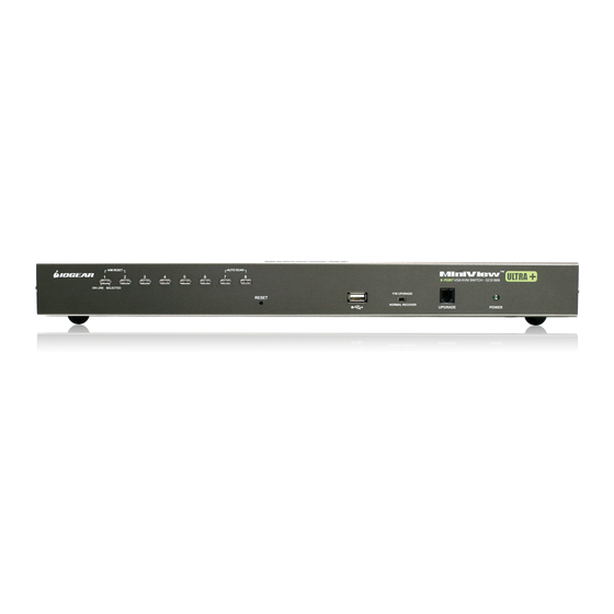
Page 6: Gcs1808 Overview
GCS1808 Overview Port 1~8 switch Button Firmware Upgrade Recovery Switch Reset Button Firmware Upgrade Cable Port USB Sharing Port* Power LED Front view *Note: The USB sharing device can only be used if your computer is connected to the KVM via a USB KVM Cable. - Page 7 Power Jack CPU1~8 Port Console Port Grounding Cable Tie Slot CONSOLE PS/2-USB Back view...
-
Page 8: Gcs1716 Overview
GCS1716 Overview Port 1~16 Switch Button Firmware Upgrade Recovery Switch Reset Button Firmware Upgrade Cable Port USB Sharing Port* Power LED Front view *Note: The USB sharing device can only be used if your computer is connected to the KVM via a USB KVM Cable. - Page 9 CPU1~16 Port Power Jack Grounding Console Port Cable Tie Slot CONSOLE PS/2-USB Back view...
-
Page 10: Foot Pad Set Installation
Foot Pad Set Installation Flip the KVM switch upside down. Peel the protective films off of the foot pads, then stick the pads to the four corners, as shown in the diagram below. -
Page 11: Rack Mounting
Rack Mounting Step 1 Remove the screws from the left and right sides of the switch (2 screws total) near the front of the switch. - Page 12 Step 2 Use the M3 x 8 Phillips hex head screws supplied with the rack mounting kit to screw the rack mounting brackets into the sides near the front of the unit.
- Page 13 Final Step Place the KVM switch in the rack. Position it so that the holes in the mounting brackets line up with the holes in the rack. Secure the mounting brackets to the front of the rack.
-
Page 14: Grounding
Grounding To prevent damaging your equipment, it is important that all devices are properly grounded. Use the included grounding wire to ground the KVM switch by connecting one end of the wire to the grounding terminal, and the other end of the wire to a suitable grounded object. CONSOLE PS/2-USB... -
Page 15: Single Level Installation
Single Level Installation Step 1 Step3 Please make sure your computers and monitor are Connect the Console cable to the Console port powered off before you start. of the KVM. Step 2 Connect the power adapter to the power outlet and the DC jack of the KVM. - Page 16 Step 4 Connect your VGA monitor and USB or PS/2 keyboard and mouse to the console Cable. CONSOLE PS/2-USB PS/2...
- Page 17 Step 5 Connect a USB KVM Cable (with a green connector) or PS/2 KVM Cable (with a yellow connector) from the KVM switch to each of your computers. USB KVM Cable PS/2 KVM Cable Connection Connection Final Step Turn on your computers.
-
Page 18: 2-Level Installation (Cascading)
2-Level Installation (Cascading) Step 1 Step 4 Please make sure your computers and monitor are Connect your VGA monitor and USB or PS/2 powered off before you start. keyboard and mouse to the console Cable Step 2 Connect the power adapters to the power outlet and the DC jack of the KVMs. - Page 19 Step 5 Connect the Cascade Cable between the 1st level KVM and 2nd level KVM. Connect the green connector to 1 of the 1st level KVM switch’s CPU port. Then, connect the yellow connector to the console port of the 2nd level KVM switch.
- Page 20 Step 6 Connect a USB KVM Cable (with a green connector) or PS/2 KVM Cable (with a yellow connector) from the 2nd level KVM switch to each of your computers. CONSOLE PS/2-USB 2nd Level...
- Page 21 USB KVM Cable Connection PS/2 KVM Cable Connection Final Step Turn on your computers.
-
Page 22: Led Indication
LED Indication Description No LED No computer is connected to the specific port or the computer is connected to the specific port but it is not powered on Orange The specific port has a computer connected and it is powered on, but does not focus on the KVM Green The specific port has focus on the KVM... -
Page 23: Port Switching
Port Switching Port Switching via Front Panel Switch Button Simply press the specific push button to switch the focus to the specific port Port Switching via On-Screen DIsplay (OSD) Please refer to OSD Operation section. Port Switching via Hotkey Please refer to Hotkey Setting Mode (HSM) section. -
Page 24: On-Screen Display (Osd) Operation
On-screen Display (OSD) Operation Trigger OSD OSD Main Screen Simply press [Scroll Lock] [Scroll Lock] rapidly. When you invoke the OSD, a screen similar to the one below appears: Note: This hotkey sequence can be changed to [Ctrl] [Ctrl]. Please refer to Hotkey Setting Mode (HSM) section. - Page 25 Notes: The diagram depicts the administrator’s main screen. The user main screen does not show the F4 and F6 functions, since these are reserved for the administrator and can’t be accessed by users. The OSD always starts in list view, with the highlight bar at the same position it was in the last time it was closed.
- Page 26 OSD Main Screen Headings Heading Description This column lists the port ID numbers for all the KVM ports on the installation. The simplest method to access a particular computer is move the highlight bar to it then press Enter. QV If a port is selected for quick view scanning an arrowhead shows in this column.
- Page 27 OSD Navigation • After executing any action, you automatically • To dismiss the menu, and deactivate OSD, go back to the menu one level above. click the X in the upper right corner of the OSD window; or press [Esc]. OSD Function •...
- Page 28 F1: GOTO F1: GOTO If [1] was chosen, then type in the port’s name that This function is to let you switch to a specific port you want to go to and then press [Enter]. You can via port ID or port’s name. Enter [1] to choose from also move the red highlight bar to the specific port Port Name and [2] to choose from Port Number in that you want to go to and press [Enter].
- Page 29 F2: LIST If [2] was chosen then you can go to a specific port F2: LIST by entering the port ID. You can also move the red This function allows you to choose a way that you highlight bar to the specific port that you want to wish to list the ports in the OSD display on the go to and press [Enter].
- Page 30 Function Description List out all ports that the administrator has set as accessible for the current logged in user Quick View List out only the ports that have been set as quick view ports Powered ON List out only the ports that have been powered on Quick View + Pow- List out only the ports that have been set as quick view ports and they have ered ON...
- Page 31 F3: SET F3: SET OSD Hotkey There are 10 different settings within the SET This function allows you to switch the way to section, which they are as follow: trigger the hotkey between [Scroll Lock] [Scroll Lock] and [Ctrl] [Ctrl]. Simply move the red OSD Hotkey highlight bar to the hotkey setting that you would Port ID Display Position...
- Page 32 Port ID Display Duration Port ID Display Position This function allows you to change the port ID This function allows you to change the position display duration between 3 seconds and off. of the port ID that’s showing on the screen as the Simply move the red highlight bar to the option image below.
- Page 33 Scan Duration Port ID Display Mode This function allows you to set the autoscan time This function allow you to choose the way you interval between 0 second to 255 seconds (5 want to show the ports in the OSD main screen – second is set by default).
- Page 34 Scan-Skip Mode This function allows you to set the behavior in autoscan mode. Simply move the red highlight bar to the behavior you want and press [Enter]. Then, press [Esc] to exit from this function. Function Description Scan all ports that the administrator has set as accessible for the current logged in user...
- Page 35 Screen Blanker Hotkey Command Mode This function allows you to set the time interval to This function allows you to enable or disable the have the KVM goes to a black screen. Simply en- hotkey commands. Simply press Y for yes and N ter the number between 0 to 30 and press [Enter];...
- Page 36 OSD Language Hotkey This function allows you to choose the OSD This function allows you to set the hotkey language between English, Deutsch, Japanese, sequence that you wish to use to trigger hotkeys Simplified Chinese and Traditional Chinese. Simply commands. Simply move the red high light bar to move the red high light bar to the language that choose the sequence that you wish to use and youwish to choose and press [Enter].
- Page 37 F4: ADM F4: ADM Set User Login This function will only be shown if you have login This function allows you to setup the login name as Administrator. There are 11 different functions and password for the users accounts. There are within the ADM section, which they are as follow: 5 user accounts in the system –...
- Page 38 Once the user name and password are set Then simply type in the user name and correctly, you will see the message in the bottom of password. Then, enter the password again for the screen indicating the setup is ok. Then simply confirmation then press [Enter].
- Page 39 Set Accessible Ports This function allows you to setup the access on each port for each user. Use [Spacebar] to cycle through all the entries and press [Enter] to complete the setup. Then, press [Esc] to exit from the function. Function Description F (Full)
- Page 40 Set Logout Timeout Edit Port Names This function allows you to set a time that the KVM This function allows you to customize a name will automatically logout after being idle for a certain on each port of the KVM. Simply move the red period of time.
- Page 41 Restore Default Values Enter the port name that you wish to show in OSD This function allows you to restore all settings into for that specific port and press [Enter] to complete factory default settings. Move the red highlight the editing. Then, press [Esc] to exit from this bar to Restore Default Values and press [Enter].
- Page 42 Activate Beeper Clear The Name List This function allows you to enable or disable the This function allows you to clear up all the port beeper sound while switching port. Move the red names to blanks. Move the red highlight bar to highlight bar to Activate Beeper and press [Enter].
- Page 43 Set Quick View Ports This function allows you to set the desire ports as Quick View Ports. If a port is selected as a Quick View Port, an icon will show in the QV column of the OSD main screen. Simply more the red highlight bar to the desire port and press [Spacebar] to select the port as a Quick View Port.
- Page 44 Set Operating System This function allows you to define what kind of operating system is being used in each port. Simply move the red highlight bar to the desire port and press [Spacebar] to cycle through the options between WIN, MAC, SUN or OTHER. Note: The keyboard Operating platform will changed accordingly depending what you have chosen in this function.
- Page 45 Firmware Upgrade After you type Y, you will see the below screen. This function allows you to have the KVM activates The KVM is now in firmware upgrade mode. the firmware upgrade mode so that you can Please see Firmware Upgrade section for details perform a firmware upgrade to the KVM.
- Page 46 Keyboard Language This function allows you to choose the keyboard language of your console keyboard. Auto is chosen by default; if you want to change the language, simply move the red highlight bar to the desire keyboard language that you wish to change to and then press [Enter].
- Page 47 F5: SKP F5: SKP Function Description This function allows you to trigger Skip Mode. Simply press [F5] to activate skip mode. When [←] Switch to the last accessible port you see a left and right arrow next to the port number as the image below, you can press the Switch to the next accessible port [→]...
- Page 48 F6: BRC / F7: SCAN F6: BRC F7: SCAN This function will only be shown if you have login This function allows you to autoscan all the as Administrator. Simply press [F6] to trigger available ports. (This autoscan behavior depends Broadcast (BRC) Mode, then you will see a on the Scan-Skip Mode and Scan Duration.) speaker symbol next to the port number.
- Page 49 Press and hold This function allows you to logout of the OSD. So, Port 7 and Port 8 pushbutton on the GCS1808 when another person is trying to access this from (Port 15 and Port 16 for GCS1716) to trigger the console, he would have to login again.
-
Page 50: Hotkey Setting Mode (Hsm)
Hotkey Setting Mode (HSM) Function Description Press and hold [Num Lock] Invoking hotkey setting mode Press and release [-] Release [Num Lock] Note: To exit HSM manually, press Esc or spacebar. Invoke HSM, then press [h] Change the HSM invocation keys from [Num Lock] to [Ctrl] and from [-] to [F12] Invoke HSM, then press [t] Switch port switching hotkey sequence between [Scroll Lock]... - Page 51 *Note: X and Y are intervals from 1-8 (for GCS1808) and 1-16 (for GCS1716). When you enter, please make sure you enter each of them as a 2 digit number, for example, you would need to type 01 for port 1.
-
Page 52: Mac Keyboard Emulation
Mac Keyboard Emulation The PC compatible (101/104 key) keyboard can emulate the functions of the Mac keyboard. The emulation mappings are listed in the table below. PC Keyboard Mac Keyboard [Alt] [Shift] Shift [Print Screen] [Crtl] Ctrl [Scroll Lock] [Ctrl] [1] [Enter] Return... -
Page 53: Sun Keyboard Emulation
Sun Keyboard Emulation The PC compatible (101/104 key) keyboard can emulate the functions of the Sun keyboard. The emulation mappings are listed in the table below. [Ctrl] [F9] Find PC Keyboard Sun Keyboard [Crtl] [F10] [Crtl] [t] Stop [Crtl] [F2] Again [Crtl] [1] [Crtl] [2]... -
Page 54: Factory Default Settings
Factory Default Settings Function Default Settings OSD Hotkey [Scroll Lock] [Scroll Lock] Invoking HSM [Num Lock] [-] Auto Scan Duration 5 seconds Scan-Skip Mode Screen Blanker Beeper Keyboard Operating Platform PC Compatible Port ID Display Position Upper left corner Port ID Display Duration 3 seconds Port ID Display Mode Port Number + Port Name... -
Page 55: Firmware Upgrade
KVM. software. Then double click on the execute file to begin with the Firmware Upgrade Utility. Step 2 Go to www.iogear.com to download the latest available firmware or the specific firmware that you wish to upgrade to. - Page 56 Step 5 Step 6 Read the License Agreement and click “I Agree” Choose the correct KVM* that you wish to perform then click “Next” if you wish to continue with the firmware upgrade from the “Device List” and then firmware upgrade. Otherwise, click “Cancel” to click “Next”...
- Page 57 Step 7 Step 8 If you have checked the “Check Firmware Version” Warning window may popup again for 2nd part of checkbox, then the utility will check the current the firmware upgrade (IO1). firmware that is on your KVM. If the current firmware is newer than the firmware that you wish to upgrade to, a window will popup and prompt you to ask if you wish to proceed.
- Page 58 Final Step Step 10 Now the KVM will reset by itself and it will be ready When the firmware upgrade is done, you will see for usage after the rest. “Firmware upgrade OK” in the “Status Messages” window. Then simply click “Finish” to complete the whole firmware upgrade process.
-
Page 59: Upgrade Fail
Upgrade Fail Step 3 If you don’t see “Firmware upgrade OK” in the Repeat the firmware upgrade process. (Please refer “Status Messages” window, it means the utility has to Firmware Upgrade section) failed to complete the firmware successfully. If that occurs, please do the following: Step 4 After the firmware upgrade has completed, the KVM... -
Page 60: Restore Factory Default Settings
Restore Factory Default Settings This restore will change all settings back to default. This will also have administrator and all user accounts removed from the KVM. All port names and setting will also be removed. In other words, everything will be changed as if it is a brand new unit. - Page 61 Step 3 Step 5 Now plug the DC connector back into the DC Unplug DC connector from the KVM, then remove jack from the KVM. This will restore the KVM with the jumper and screw the housing back on the factory default firmware.
-
Page 62: Federal Communications Commission (Fcc) Statement
Federal Communications Commission (FCC) Statement 15.21 You are cautioned that changes or modifications not expressly approved by the part responsible for compliance could void the user’s authority to operate the equipment. 15.105(b) his equipment has been tested and found to comply with the limits for a Class B digital device, pursuant to part 15 of the FCC rules. - Page 63 THIS DEVICE COMPLIES WITH PART 15 OF THE FCC RULES. OPERATION IS SUBJECT TO THE FOL- LOWING TWO CONDITIONS: 1. this device may not cause interference and 2. this device must accept any interference, including interference that may cause undesired operation of the device.
-
Page 64: Ce Statement
CE Statement This device has been tested and found to comply with the requirements set up in the council directive on the approximation of the law of member states relating to EMC Directive 89/336/EEC, Low Voltage Directive 73/23/EEC and R&TTE Directive 99/5/EC. The product has been approved for LVD and covered the following countries: Belgium, Denmark, France, Germany, Italy, Portugal, U.K., Spain, Sweden... -
Page 65: Limited Warranty
For further inquiries please contact IOGEAR. -
Page 66: Contact
Contact IOGEAR 23 Hubble Irvine, CA 92618 P 949.453.8782 F 949.453.8785 Visit us at: www.iogear.com... - Page 68 About Us About Us IOGEAR offers connectivity solutions that are innovative, fun, and stylish, helping people enjoy daily life using our high technology products. GREEN IOGEAR is an environmentally conscious company that emphasizes the importance of conserving natural resources. The use of our technology solutions helps reduce electronic waste.
Need help?
Do you have a question about the GCS1808 and is the answer not in the manual?
Questions and answers