Table of Contents
Advertisement
Quick Links
Advertisement
Table of Contents

Related Manuals for IOGear MiniView G-CS102U


Summary of Contents for IOGear MiniView G-CS102U
- Page 2 Computer, Inc. ATEN is a registered trademark of ATEN Technology, Inc. IOGEAR is a registered trademark of ATEN Technology, Inc. ATEN Technology makes no warranty of any kind with regards to the information presented in this document. All information fur- nished here is for informational purposes only and is subject to change without notice.
- Page 3 Packing List & System Requirements Packing List & System Requirements This complete IOGEAR MiniView package consists One MiniView : USB KVM switch Two or four USB A-B cables Two or four VGA cables One DC 5V Power Adapter One User Manual & Quick Setup Guide Please check to make sure that all components are included and nothing is damaged.
-
Page 4: Table Of Contents
Component Overview ….…..………… Front View Back View ………………………………….. Installation …………………………..… Connection Diagram …..…………..… Operation ………………...…………..… Manual Port Selection 11 11 Auto Scan Mode Appendix A ……………………………… Troubleshooting Appendix B ……………………………… Contacting IOGEAR Appendix C ………………………………. Radio & TV Interference Statement Limited Warranty... -
Page 5: Introduction
: USB. If you have any questions or comments regarding this product, or any other IOGEAR products, please feel free to contact us. Full contact information is available on the Contacting IOGEAR page in this manual. Rest as- : USB as... -
Page 6: Features
Features Features Use one keyboard, monitor and mouse to control be- tween two and four PCs. Share four USB devices among attached com- puters. USB 1.1 compliance ensures full compatibility with your USB devices. Operating System-independent operation. Connected PC’s can be added or removed from the setup without powering off the KVM switch. -
Page 7: Specifications
Specifications Specifications i t s ° 5 ° 0 ° 0 ° 0 y t i " " " " " "... -
Page 8: Component Overview
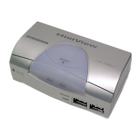
Overview Overview Front View: 1 Selected LEDs These LEDs indicate the currently selected port. 2 Auto Scan LED The Auto Scan LED flashes when Auto Scan Mode is in effect. 3 Port Selection Switch The Port Selection Switch is located on the front panel, just opposite the Select Arrow on the front panel. - Page 9 Overview... Overview...
-
Page 10: Back View
Overview... Overview... Rear View 1.) Console Video Connector Connect your monitor here. 2.) Power Jack If you choose to use an external DC 5V power adapter, connect it here. 3.) Scan Time Selection Switch This slide switch selects the amount of time the MiniView : USB will monitor each port (3 or 15 seconds) when Auto Scan Mode is enabled. - Page 11 Overview... rview...
-
Page 12: Installation
Installation Installation Before you begin, make sure that power to your com- puters and peripherals (monitor, scanner, etc.) is turned off. 1.) Connect your monitor to the Console Video Port on the MiniView : USB. 2.) Connect your USB peripherals to the USB Downstream Ports on the MiniView : USB. -
Page 13: Connection Diagram
Connection Diagram Connection Diagram... -
Page 14: Operation
Operation Operation Note: The drivers for some USB devices may need to be un-initialized before you disconnect the device, or the sys- tem may crash. When you switch computers with the Port Selection Switch or Auto Scan Mode, it is the equivalent of disconnecting the device. -
Page 15: Auto Scan Mode
Operation... Operation... Auto Scan Mode The MiniView : USB Auto Scan feature automatically switches among the attached computers at regular inter- vals (3 or 15 seconds), so that you can monitor their activity without having to take the trouble of switching ports your- self. - Page 16 Appendix A Appendix A Troubleshooting Note: The drivers for some USB devices need to be un- initialized before you disconnect the device, or the system may crash. When you switch computers with the Port Selection Switch, it is the equivalent of disconnecting the device.
- Page 17 Appendix B Appendix B Contacting IOGEAR In the event that your MiniView fails to function properly, or you wish to contact us for any other reason, here are a few ways to do so. IOGEAR 16560 Aston Street Irvine, CA 92606...
- Page 18 Appendix C Appendix C Radio & TV Interference Statement This equipment has been tested and found to comply within the limits for a Class B digital device, pursuant to Part 15 of the FCC Rules. These limits are designed to provide rea- sonable protection against harmful interference in a resi- dential installation.
Need help?
Do you have a question about the MiniView G-CS102U and is the answer not in the manual?
Questions and answers