Table of Contents
Advertisement
Quick Links
WARNING:
If the information in these instructions are not followed exactly, a fire or
explosion may result causing property damage, personal injury or loss of life.
-
Do not store or use gasoline or other flammable vapors and liquids in the vicinity of this or
any other appliance.
WHAT TO DO IF YOU SMELL GAS
¥ Do not try to light any appliance.
¥ Do not touch any electrical switch; do not use any phone in your building.
¥ Immediately call gas supplier from a neighbor's phone. Follow the gas supplier's instructions.
¥ If you cannot reach your gas supplier, call the fire department.
-
Installation and service must be performed by a qualified installer, service agency or the gas
supplier.
This appliance may be installed as an OEM installation in a manufactured (mobile) home and
must be installed in accordance with the manufacturerÕs instructions and the manufactured
home construction and safety standard, Title 24 CFR, Part 3280 or Standard for Installation in
Mobile Homes, CAN/CSA Z240 MH.
This appliance is only for use with the type(s) of gas indicated on the rating plate. A conversion
kit is supplied with the appliance.
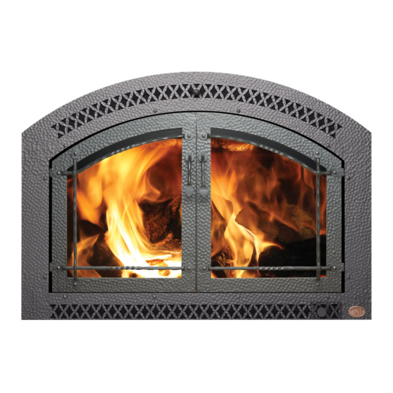
44 DV XXL Owner's Manual
Installer:
After installation give this manual to the
homeowner and explain operation of this
fireplace.
$ 1 0 . 0 0
- July, 1999 -
Part # 93508109
TM
¥
Direct Vent Fireplace
¥ Natural Gas or Propane
¥ Standard Residential
¥ Mobile Home Approved
Tested and Listed by
Omni-Test Laboratories, Inc.
Beaverton, Oregon
Report # 028-5-26-5
ANSI Z21.88, CSA 2.33 M9 8, CAN/CGA 2.17-M91
10850 117th Place N.E. Kirkland, WA 98033
Advertisement
Table of Contents

Subscribe to Our Youtube Channel
Related Manuals for FireplaceXtrordinair 44 DV XXL


Summary of Contents for FireplaceXtrordinair 44 DV XXL
-
Page 1: Introduction & Important Information
Mobile Homes, CAN/CSA Z240 MH. This appliance is only for use with the type(s) of gas indicated on the rating plate. A conversion kit is supplied with the appliance. 44 DV XXL Owner’s Manual - July, 1999 - Installer: After installation give this manual to the homeowner and explain operation of this fireplace. -
Page 2: Safety Precautions
Safety Precautions • IF YOU SMELL GAS: * Do not light any appliance * Extinguish any open flame * Do not touch any electrical switch or plug or unplug anything * Open windows and vacate building * Call gas supplier from neighbor's house, if not reached, call fire department •... -
Page 3: Safety Precautions
Safety Precautions ¥ Do not place clothing or ¥ Light the heater using the other flammable items on or built-in piezo igniter. Do not near the heater. Because use matches or any other this heater can be controlled external device to light your by a thermostat there is a heater. -
Page 4: Table Of Contents
Table of Contents Introduction Finalizing the Installation Introduction & Important Information....1 1 Glass Removal (& installation)......27 2 Log Installation .........28 Safety Precautions 3 Replace the Glass ........33 Safety Precautions ........2 4 Faceplate Installation .........33 Features & Specifications 5 Leak Test..........33 6 Pilot Adjustment (if necessary).....33 Features ............5 7 Air Shutter Adjustment (if necessary) ....34... -
Page 5: Features & Specifications
Features and Specifications Features: Installation Options: Works During Power Outages (millivolt system) Residential or Mobile Home High Efficiency Straight or Corner Placement Optional Thermostat or Remote Control Flush or Recessed Face Realistic "Wood Fire" Look Raised or Floor Hearth Two Quiet Blowers for Effective Heat Distribution Internal or External Chase Convenient Operating Controls Horizontal or Vertical Vent... -
Page 6: Installation
This appliance may be installed in Manufactured Housing only after the home is site located. The 44 DV XXL is designed to operate on natural gas or propane (LP). All exhaust gases must be vented outside the structure of the living-area. -
Page 7: Fireplace Placement Requirements
Installation (for qualified installers only) Fireplace Placement Requirements Minimum Framing Dimensions The 1Ó stand-offs along the front corners, the 1Ó clearance requirement around the sides and back, and the 10-1/2" stand-offs on the top of the fireplace separate the fireplace from combustible materials (e.g.: combustible framing members, plywood, sheetrock, paper-backed insulation). -
Page 8: Clearances
Installation (for qualified installers only) Clearances • When installed, walls in front of the fireplace must be a minimum 3-1/2" to the side of the faceplate. • Fireplace must be placed so that no combustibles are within, or can swing within 36" of the front of the fireplace (e.g. -
Page 9: Corner Installations
Installation (for qualified installers only) Corner Installations A typical 45¡ installation uses the minimum framing dimensions shown in the illustration below (NOTE: all clearances still apply). 19-5/8" 19-1/2" 1" Standoffs 23-1/8" 60-3/8" Min. 1" Clearance Approx. 16-3/4" Raised Fireplaces • The fireplace (and hearth, if desired) may be placed on a platform designed to support the fireplace (approximately 300 Lbs.) and vent. -
Page 10: Hearth Requirements
Installation (for qualified installers only) Hearth Requirements Floor Mounted Fireplaces 6-1/4" Do not build the hearth above this ledge. Tile, Marble, Brick, or other Non-Combustible Decorative Trim (may be combustible) 53" Min. Min. 3/4Ó Max. 15/16Ó 12Ó Min. Cement Board 6-1/4"... -
Page 11: Facing Requirements
Installation (for qualified installers only) Facing Requirements NOTE: The combustible area above the facing must not protrude more than 3/4" from the facing. If it does, it is considered a mantel and must meet the mantel requirements listed in this manual. The fireplace requires a concrete board (or other non-combustible) extending from the header to the floor and to the framing... -
Page 12: Facing Detail
Installation (for qualified installers only) Facing Detail NOTE: The overlap is 1-1/2" along the top of the face. 1/4" Arch Faces 4 " Face 1" Glass Access Door 1/2" Air Space Do not tuck tile underneath the face on the bottom (there will be a 1/2"... -
Page 13: Face Dimensions
Installation (for qualified installers only) Face Dimensions 6-3/8" Radius = 45-3/8Ó 33-7/8" Access Door 46Ó Travis Industries 9 3 5 0 8 1 0 9 1 8 0 5 0 1... -
Page 14: Facing And Hearth Examples
Installation (for qualified installers only) Facing and Hearth Examples Side View Face Fireplace SUGGESTION: If using a hearth, make your platform height a dimension that will accommodate the size tiles 1" you are using and the 1" between the base of Base of Fireplace the fireplace and the bottom of the face. -
Page 15: Side View
Installation (for qualified installers only) Facing and Hearth Examples (continued) Side View Fireplace Face 1/2" Cement Board & 3/8" thick tile (tucked behind the face) 3/8" Thick Tile 1/2" Cement Board 1" Wood Sub Base of Fireplace Floor Three-Dimensional View Face NOTE: Note how the... -
Page 16: Mantel Requirements
Installation (for qualified installers only) Mantel Requirements ¥ The combustible area above the facing must not protrude more than 3/4" from the facing. If it does, it is considered a mantel and must meet the mantel requirements listed in this manual. Combustible or Non-Combustible Mantels Combustible Mantel Max. -
Page 17: Vent Requirements
Installation (for qualified installers only) Vent Requirements The vent must maintain the required clearance to combustible materials to prevent a fire (see ÒClearancesÓ below). Do not fill air spaces with insulation. The gas appliance and vent system must be vented directly to the outside of the building, and never be attached to a chimney serving a separate solid fuel or gas-burning appliance. -
Page 18: Vent Installation
Installation (for qualified installers only) Vent Installation ¥ In addition to the requirements below, follow the requirements provided with the vent. Vertical Vent Vertical Termination Requirements (part # 1291) Use a roof flashing and storm collar Combustible whenever passing through the roof Framing Use the Simpson ceiling firestop (#1263) whenever passing through a ceiling (or enclosure and at every... -
Page 19: Approved Vent Configurations
Installation (for qualified installers only) Approved Vent Configurations Restrictor Position • A vent restrictor is built into the appliance to adjust the flow rate of exhaust gases. This ensures proper combustion for all vent configurations. Depending upon the vent configuration, you may be required to adjust the restrictor position. -
Page 20: Vertical Term. 0,2 Or 4 45¡ Offsets
Installation (for qualified installers only) Vertical Terminations with 0, 2, or 4 45¡ Offsets ¥ Use 8Ó diameter co-axial vent Horizontal Offset ¥ A Maximum of Four 45¡ Elbows May be Used Vertical ¥ 8Õ Minimum System Height (without offsets) Rise ¥... -
Page 21: Horizontal Term. With One Vert. Elbow
Installation (for qualified installers only) Horizontal Terminations with One Vertical Elbow The termination must fall within the shaded area shown in the chart. Use the indicated restrictor position. NOTE: Vertical ¥ One horizontal elbow (45¡ or 90¡) is allowed (except in Elbow those configurations that lie in the region under "Restrictor Postion #1"... -
Page 22: Horizontal Term. With Three Vert. Elbows
Installation (for qualified installers only) Horizontal Terminations with Three Vertical Elbows The termination must fall within the shaded area shown in the chart. Use the indicated restrictor position. NOTE: ¥ A total of three elbows must be used. ¥ No horizontal elbows may be used (a horizontal elbow is defined as an elbow that directs the vent from a horizontal direction to another horizontal direction). -
Page 23: Vertical Term. With Two Elbows
Installation (for qualified installers only) Vertical Terminations with Two Vertical 90¡ Elbows The termination must fall within the shaded area shown in the chart. Use the indicated restrictor position. 40' (max) 40' (max) Restrictor Position # 3 NOTE: Restrictor positions are 35 feet 35 feet based upon lab tests. -
Page 24: Vent Termination Requirements
Installation (for qualified installers only) Termination Requirements (see the illustration below) Venting terminals shall not be recessed into a wall or siding. Minimum 9" clearance from any door or window Roof Minimum 12" above any grade, veranda, porch, deck or balcony Surface Minimum 12"... -
Page 25: Gas Line Requirements
Installation (for qualified installers only) Gas Line Requirements The gas line must be installed in accordance with all local codes, if any; if not, follow ANSI 223.1 and the requirements listed below. The fireplace and gas control valve must be disconnected from the gas supply piping during any pressure testing of that system at test pressures in excess of 1/2 psig. -
Page 26: Electrical Connection
Installation (for qualified installers only) Electrical Connection Make sure the household breaker is shut off prior to working on any electrical lines. The appliance, when installed, must be electrically grounded in accordance with local codes or, in the absence of local codes, with the National Electrical Code, ANSI NFPA 70, or the Canadian Electrical Code, CSA C22.1. -
Page 27: Glass Removal (& Installation)
Finalizing the Installation (for qualified installers only) Remove the glass (and arch covers) following the directions below. Warning: The appliance must be completely cool before removing the glass. Warning: To prevent damage, do not abuse, strike, or slam the glass shut. Note: Attach the arch covers after re-installing the glass. -
Page 28: Log Installation
Finalizing the Installation (for qualified installers only) If converting this unit to propane, do so now (see the instructions on page 46). Install the rock wool, log set, kibbles, and embers (if using the decorative fireback, install it prior to the log set - page 57). - Page 29 Finalizing the Installation (for qualified installers only) (c) Front Log Installation (has a #3 stamped on bottom) Place the front log. Note how the square notch on the log fits over the pilot assembly (this illustration shows the front log rotated forward).
-
Page 30: Finalizing The Installation
Finalizing the Installation (for qualified installers only) (d) Left Log Installation (has a #2 stamped on bottom) Center the left log on this ledge. Slide the log all the way to the right. TOP VIEW Travis Industries 9 3 5 0 8 1 0 9 1 8 0 5 0 1... - Page 31 Finalizing the Installation (for qualified installers only) (e) Left Twig Installation (has a #5 stamped on bottom) Place the left twig so this hole lines up with this pin. This pin goes into this slot. (f) Right Twig Installation (has a #4 stamped on bottom) The right twig fits directly in front of this burner tube.
- Page 32 Finalizing the Installation (for qualified installers only) (g) Optional Coal ÒKibbleÓ and Steel Ember Installation Kibbles may be placed on the tray welded to the front burner - do not place the kibbles directly over the burner holes. Place the optional kibbles in front of the firebox.
-
Page 33: Replace The Glass
Finalizing the Installation (for qualified installers only) We recommend you purge the gas line at this time (with the glass removed). This allows gas to be detected once it enters the firebox, ensuring gas does not build up. Replace the glass (and arch covers when using arched faces - see page 27). Turn on the gas to the fireplace. -
Page 34: Air Shutter Adjustment (If Necessary)
Finalizing the Installation (for qualified installers only) Adjust the front air shutter if necessary. Front Burner (front) Adjusting the Front Burner Turn the heater off and let it cool completely. Remove the glass and logs. Locate the front burner air shutter, loosen the lock screw holding the shutter in place, and rotate the air shutter to a more open position. -
Page 35: Check Flame
Finalizing the Installation (for qualified installers only) Turn the flame adjust knob to its highest position - the flames should be approximately 12" tall. Check the flame on low position. The flames should burn off of each burner hole. If the heater does not work correctly, contact your dealer for a remedy. -
Page 36: Operation
Operation Before You Begin Warning: Read this entire manual before you use your new fireplace (especially the section "Safety Precautions" on pages 2 & 3). Failure to follow the instructions may result in property damage, bodily injury, or even death. Warning: Do not operate appliance with the glass front removed, cracked or broken. -
Page 37: Starting The Pilot
Operation Starting The Pilot Flame The pilot flame is required to ignite the main burners (it also plays a safety role). It should be left on once lit. It will stay lit unless the gas control valve is turned to "OFF". However, the pilot will go out if the gas is shut off, the propane tank runs out (or low) or if the stove malfunctions. -
Page 38: Starting The Fireplace For The First Time
Operation Starting the Fireplace for the First Time Burn the heater at a high setting with the blower off for an extended period (up to 48 hours). This will cure the painted surfaces. Fumes from the paint curing and oil burning off the steel will occur. This is normal. -
Page 39: Adjusting The Blower Speed
Operation Adjusting the Blower Speed The internal blower helps transfer Blower Knob the heat from the fireplace into the room. It will not turn on until the Turn the knob all the way counter-clockwise to turn fireplace is up to temperature the blower off. -
Page 40: Maintenance
Maintenance (for qualified service personnel only) Maintaining Your Fireplace's Appearance Fingerprints or other marks left on the optional gold surface may become etched in place if they are not wiped clean prior to turning the heater on. Clean gold with denatured alcohol and a soft cloth (make sure the fireplace is cool). -
Page 41: Troubleshooting Table
Maintenance (for qualified service personnel only) Troubleshooting Table Problem: Possible Cause: Don't Call for Service Until You: A gas shut off valve is turned off Check all gas shut off valves Pilot Will Not Light The gas control knob isn't turned to "PILOT" See "Starting the Pilot Light"... -
Page 42: How This Fireplace Works
Maintenance (for qualified service personnel only) How this Fireplace Works This fireplace was designed with safety as the primary concern. Many of the components inside this fireplace are for safety purposes. Therefore, only certified gas service technicians should service this fireplace. -
Page 43: Wiring Diagram
Maintenance (for qualified service personnel only) Wiring Diagram Caution: Label all wires prior to disconnection when servicing controls. Wiring errors can cause improper and dangerous operation. Piezo Igniter Millivolt Wiring Thermopile (for gas control valve) Gas Control Valve Orange Brown Jumper Wire Thermocouple (Manual Operation) -
Page 44: Safety (Listing) Label
Safety Label The safety (listing) label is on a plate chained to the gas control valve. A copy of the safety label is shown below. Travis Industries 9 3 5 0 8 1 0 9 1 8 0 5 0 1... -
Page 45: Warranty
Warranty To register your TRAVIS INDUSTRIES, INC. 7 Year Warranty, complete the enclosed warranty card and mail it within ten (10) days of the appliance purchase date to: TRAVIS INDUSTRIES, INC., 10850 117th Place N.E., Kirkland, Washington 98033. TRAVIS INDUSTRIES, INC. warrants this gas appliance (appliance is defined as the equipment manufactured by Travis Industries, Inc.) to be defect-free in material and workmanship to the original purchaser from the date of purchase as follows: Years 1 &... -
Page 46: Optional Equipment
Optional Equipment (for qualified installers only) LP Conversion Instructions Remove the four screws holding Install the conversion the front and main burner in place. kit prior to installing the gas line to 1/4" Nutdriver ensure proper gas u s e . Remove the glass (see page 27). - Page 47 Optional Equipment (for qualified installers only) Follow the directions below to remove the natural gas orifices. Apply thread sealant to the LP orifices and tighten them in place with a 1/2" open end wrench (make sure to install the orifices correctly Ð see the illustration below).
- Page 48 Optional Equipment (for qualified installers only) Remove the pilot orifice following the instructions below. Replace with the propane pilot orifice. The propane conversion kit includes a .016Ó (labeled LP 16) or .011Ó (labeled LP 11) pilot orifice. The .016Ó orifice is preferred because it allows for greater pilot adjustment. VIEW FROM THE REAR Orifice Identification: Pull the pilot orifice...
- Page 49 Optional Equipment (for qualified installers only) 1 1 Remove the regulator from the front of the gas control valve. Replace with the propane regulator, using the new gasket and screws included with the regulator. NOTE: Leak test this area after the heater is installed, gas is connected, and the main burner is lit.
-
Page 50: Power Heat Duct
Optional Equipment (for qualified installers only) POWER HEAT DUCT (part # 98500769) The optional heat duct allows the fireplace to transfer heat to separate locations in the home. One or two ducts may be used . Installation should take place prior to installing drywall. Warning: This kit must be installed as specified in these instructions. - Page 51 Optional Equipment (for qualified installers only) Attach the blower box to the framing or floorboards of the home following the instructions below. Wall or Ceiling Mounting Cut a hole between wall Slide the blower, with Attach the wall mounting framing members for the brackets to the blower box.
- Page 52 Optional Equipment (for qualified installers only) Attach the starter ring to the fireplace following the directions below (use the most convenient side). 1/4" Nutdriver Starter Ring Remove and discard the cover plate. Bend the tabs on the bottom of the starter ring up to lock it in place.
-
Page 53: Wiring Instructions
Optional Equipment (for qualified installers only) Attach the grill (and wall adapter, if necessary). Screws (included with this kit) Wall Adapter (for use when the blower box protrudes from the wall - Grill Phillips primarily on 2 x 4 walls) Screwdriver WIRING INSTRUCTIONS Warning:... - Page 54 Optional Equipment (for qualified installers only) Follow the directions below to wire the blower box. Remove the cover from the blower box. Standard Screwdriver Phillips Screwdriver Insert sheathed cable through the cable clamp. After the wires have been connected tighten the clamp to secure the cable.
-
Page 55: Maintenance Instructions
Optional Equipment (for qualified installers only) Run the free wire from the rheostat junction box to the fireplace. Follow the directions below to connect the heat duct circuit to the fireplace. Remove the cover from the Insert the sheathed cable from the rheostat through a fireplace junction box. -
Page 56: Thermostat
Optional Equipment (for qualified installers only) Thermostat (Part # 99300650) Do not connect 120 VAC to the gas control valve or wiring of this unit. Attach the thermostat wire to the on/off switch and route it through the grommet located on either side of the fireplace (see the illustration below). -
Page 57: Remote Control Thermostat
Optional Equipment (for qualified installers only) Remote Thermostat (Part # 99300654) Do not connect 110-120 VAC to the gas control valve or wiring system of this unit. • Follow the instructions included with the remote thermostat for installation. IMPORTANT OPERATIONAL NOTE FOR REMOTE THERMOSTAT USE: Included with the remote thermostat is a set of instructions that should be given to the homeowner. -
Page 58: Index
Index Approved Vent Configurations......19 Installation Options ...........5 Adjusting the Blower Speed......39 Items Required for Installation......6 Adjusting the Flame Height .......38 Leaking Gas ......See Inst. on Cover Air Shutter Adjustment........34 Listing Information ..........44 Altitude Considerations........17 Location of Controls..........36 Blower Control..........39 Log Set Installation and Removal .......28 BTU Input............5 Maintenance ............40 BTU Output............5...
Need help?
Do you have a question about the 44 DV XXL and is the answer not in the manual?
Questions and answers