Table of Contents
Advertisement
Quick Links
Advertisement
Table of Contents

Related Manuals for Norco ATX-6991


Summary of Contents for Norco ATX-6991
- Page 1 ATX-6991 Ver: V1.1...
- Page 2 ATX-6991 Ver: V1.1 SZ HQ: 0755-27331166 Beijing Office: 010-82671166 Shanghai Office: 021-61212081 Chengdu Office: 028-85259319 Shenyang Office: 024-23960846 Xi’an Office: 029-88338386 Nanjing Office: 025-58015489 Wuhan Office: 027-87858983 Tianjin Office: 022-23727100 Singapore: 65-68530809 For more information, please visit www.norco-group.com...
- Page 3 Before ordering products, please learn about the product performance from the distributors to see if it is in line with your needs. NORCO is a registered trademark of Shenzhen NORCO Intelligent Technology CO., LTD. The ownership of other trademarks involved in this manual is owned by its respective owners.
- Page 4 Safety Instructions 1. Please read the product manual carefully before using this product. 2 . Put all the unused or uninstalled boards or electronic components in a static dissipative surface or static shielding bag. 3.Always ground yourself to remove any static discharge before touching the board, to place your hands on grounding metal object for a while or wear a anti-static wrist strap at all times.
-
Page 5: Table Of Contents
Content Chapter 1 Product Introduction ......................1 1.1 Product Introduction........................1 1.2 Hardware Specification......................1 Chapter 2 Hardware Function ......................4 2.1 Interfaces Location & Dimension.................... 4 2.2 Installation Steps........................5 2.3 Memory Installation........................5 2.4 Jumpers Setting.........................6 2.4.1 CMOS Clear/Hold Jumper Setting(JCC).............. 6 2.4.2 Auto Boot upon Restore AC Power(JAT).............. - Page 6 BIOS Setup..........................24 3.1 Main Menu..........................25 3.2 Advanced Menu........................27 3.2.1 CPU Configuration......................28 3.2.2 Power & Performance....................31 3.2.3 ACPI Settings....................... 36 3.2.4 F81866 Supper IO Configuration................37 3.2.5 Hardware Monitor......................42 3.2.6 Serial Port Console Redirection................43 3.2.7 USB Configuration....................... 45 3.2.8 CSM Configuration......................
- Page 7 Packing List Thanks for purchasing NORCO products. Please check the accessories as per the packing list when you open its package. If you find any components/parts defected, damaged or lost, please contact your vendor ASAP. ■ ATX-6991 1pcs ■Drive CD 1pcs ■Jumper cap...
- Page 8 Chapter Product Introdu ction...
-
Page 9: Chapter 1 Product Introduction
ATX-6991 User's Manual Chapter One Product Introduction 1.1 Product Introduction ATX-6991 ATX motherboard is based on Intel 8 generation Coffee lake-S desktop platform ; Adopt Intel® 300 Series chipset ; Support 8th Gen Intel® Core i7/i5/i3 CPU, etc. Provide 6xserial ports, 14xUSB (4x USB3.0、 10x USB2.0), 6xSATA, 1xLPT, 1xKM , Line out + MIC in+ Line in+ S/PDIF,8BitsGPIO,VGA+DVI+HDMI+DP,2xRJ45 network interface,... - Page 10 ATX-6991 User's Manual Ethernet ●Network controller:Using PCIe interface chip,model:I211/I210(Can be selected according to needs) ●Rate:10/100/1000Mbps self-adaption ●2xRJ45 network interface ●Support Wake On LAN(WOL) Storage ●Provide 6xstandard 7Pin SATA3.0 port Audio ●Adopt ALC662 audio control chip,support dual channel,stereo ●Port:2x tip jacks(Green for Line-out,Pink for MIC-in) ,support Line out + MIC in+ Line in+S/PDIF ●I/O chip:NCT6106D...
- Page 11 ATX-6991 User's Manual BIOS ●BIOS:AMI EFI Operating Environment ●Operating Temperature:0℃~60℃ ●Storage Temperature:-40~85℃ ●Operating Humidity:5%~95%,non-condensing ●Storage Humidity:5%~95%,non-condensing...
-
Page 12: Chapter 2 Hardware Function
Chapter Hardware Function... -
Page 13: Interfaces Location & Dimension
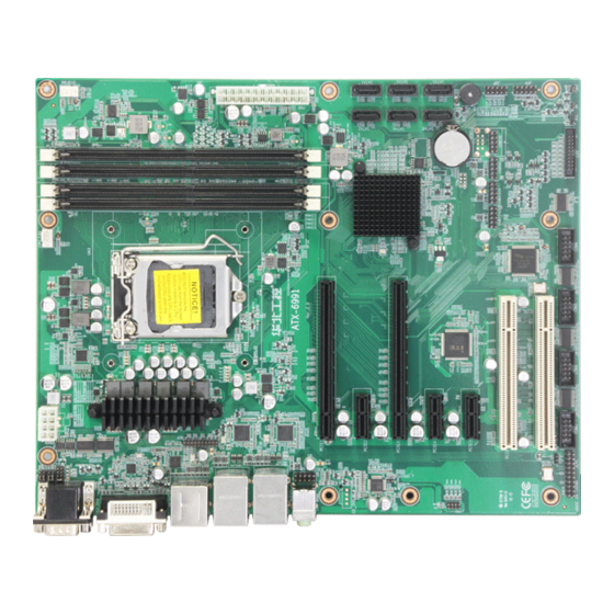
ATX-6991 User's Manual Chapter Two Hardware Function 2.1 Interfaces Location & Dimension Following picture illustrates the interfaces location and dimension of ATX-6991. Please take care of some components during the installation. Improper installation may lead to system failure. Note: In case of any electrostatic damage caused to some components, please wear... -
Page 14: Installation Steps
ATX-6991 User's Manual 2.2 Installation Steps Please refer to following steps to assemble your computer: 1.Adjust all jumpers on board ATX-6991 according to the user manual. 2.Install CPU and CPU fan 3.Install memory 4.Install other expansion cards 5.Connect all signal lines, cables, control panel circuit and power supply unit. -
Page 15: Jumpers Setting
ATX-6991 User's Manual 2.4 Jumper Settings Please refer to following instructions to do jumper settings before installing your hardware devices. Remark: How to identify the PIN1 of all jumpers and interfaces: Please observe the word mark on the side of the plug socket, which will be a “1” or bold line or triangular symbol; And please look at the back of PCB, each with a square shape will be the PIN 1;... - Page 16 ATX-6991 User's Manual JCC: Setting CLEAR NORMAL Do not clear CMOS when the computer is power on, otherwise, it will cause damage to the motherboard!
- Page 17 ATX-6991 User's Manual 2.4.2 Hardware Switch for System Auto Boot upon Power On(JAT) JAT: Setting Open Disable Auto Boot Close Enable Auto Boot...
-
Page 18: Com2 Jumpers Setting(J1,J2,J3
ATX-6991 User's Manual 2.4.3 Setting(JME) JME: Signal Name +DVDDIO_AUDIO AZA_SDO 2.4.4 COM2 Jumper Setting(J1,J2,J3) J1, 2, J3 jumper is to set COM2 transmission mode, COM2 support RS232/RS422/RS485 transmission mode. -
Page 19: Interface Specification
ATX-6991 User's Manual J1、 J2 J1、J2、J3: COM2 AS RS232 PORT COM2 AS RS422 PORT COM2 AS RS485 PORT 1-3 2-4 3-5 4-6 3-5 4-6 1-3 2-4 3-5 4-6 3-5 4-6 5-6 7-8 2.5 Interface specification Please read this manual carefully before installing any external connectors, in case of any damage to the motherboard! 2.5.1 Serial Ports(COM1,COM2,COM3-COM6,J9)... - Page 20 ATX-6991 User's Manual power supply pin,when in use, special adapter cable is needed to supply power for COM through COM port power supply (J9) interface. COM1、COM2 COM3-COM6 COM1、COM2: COM1 COM2 DCD# DATA- DATA+ SOUT HSOUT2RX+ DTR# HDTR#2RX DSR# DSR# RTS#...
-
Page 21: Sata Port(Sata1-Sata6
ATX-6991 User's Manual COM3-COM6: Signal Name Signal Name DCD# DSR# RTS# SOUT CTS# DTR# COM_PIN10 J9: Signal Name COM_PIN10 +12V 2.5.2 SATA Port(SATA1-SATA6) Provide 6x standard 7Pin SATA port. SATA1-3-5 SATA2-4-6... -
Page 22: Usb78,Usb1112,Usb1314
ATX-6991 User's Manual SATA1-SATA6: Signal Name 2.5.3 USB and LAN Port(HDMI_USB12, USB34_LAN1, USB56_LAN2, USB56, USB78,USB1112,USB1314, ) Provide 14xUSB port , HDMI_USB12 、 USB34_LAN1 、 USB56_LAN2 are double layer USB3.0 port;USB56、USB78、USB1112、USB1314 port are 2×5Pin USB2.0 pin interface. USB34_LAN1 USB56_LAN2 USB56、USB78 USB1112、USB1314... - Page 23 ATX-6991 User's Manual USB56、USB78、USB1112、USB1314: Signal Name Signal Name USBD_N USBD_P USBD_P USBD_N RJ45 LAN LED status description: LILED(Green) ACTLED(Yellow) Function Function 100/1000M link FLASH Data transfer 10M link or close Data stop...
-
Page 24: Keyboard And Mouse Interface(Km
ATX-6991 User's Manual 2.5.4 Keyboard & Mouse Interface(KM) KM: Signal Name Signal Name VCC_KM MS_CLK_R MS_DATA_R MS_DATA_R KB_CLK_R VCC_KM 2.5.5 Audio Interface(AUDIO,FP_AUDIO,J_SPDIFO,CD_IN) Adopt ALC662 audio control chip, Green for audio output interface (Line-out) , Pink for microphone input interface(MIC-in). - Page 25 ATX-6991 User's Manual AUDIO FP_AUDIO CD_IN FP_AUDIO: Signal Name Signal Name MIC2L AGND MIC2R LINE1L LINE2R LINE1R AGND LINE2L AGND J_SPDIFO: Signal Name SPDIFO...
-
Page 26: Disdplay Port(Vga_Dvi,Hdmi_Usb12,Jdp
ATX-6991 User's Manual 2.5.6 Display Port(VGA_DVI,HDMI_USB12,JDP) 1x standard DB15 VGA port,1x standard DVI-D port,1x HDMI port,1x DP port. VGA_DVI HDMI_USB12 VGA: Signal Name Signal Name VGA_R VGA_G VGA_B VGA_PIN10 VGA_SDA_R MON_HSYNC MON_VSYNC VGA_SCL_R... - Page 27 ATX-6991 User's Manual DVI: Signal Name Signal Name DVI_DATA2_N DVI_DATA2_P DVI_SCL DVI_SDA DVI_DATA1_N DVI_DATA1_P VCC_VGA_DVI DVI_DETECT DVI_DATA0_N DVI_DATA0_P DVI_CLK_P DVI_CLK_N HDMI: Signal Name Signal Name DATA2_P DATA2_N DATA1_P DATA1_N DATA0_P DATA0_N CLK_P CLK_N DETECT...
-
Page 28: Programmable Input And Output Port(Jgp
ATX-6991 User's Manual JDP: Signal Name Signal Name DP0P DP1P DP0N DP1N DP2P DP3P DP2N DP3N DPC3_AUX_DP DDIP_HPD0_DM DPC3_AUX_DN HDMI_DNG_DT VCC3 2.5.7 Programmable Input and Output Port(JGP)... -
Page 29: Power Interface(Pwr,J12V
ATX-6991 User's Manual JGP: Signal Name Signal Name GPP_G22 GPP_G18 GPP_G16 GPP_G23 GPP_G12 GPP_G15 GPP_G13 GPP_G14 2.5.8 Power Interface(PWR,J12V) Standard ATX 24Pin + 4Pin power supply. J12V PWR: Signal Name Signal Name +3.3V +12V... -
Page 30: Fan Interface(Cpu_ Fan,Sys_ Fan
ATX-6991 User's Manual +12V +5V SB PW-OK PS_ON- +3.3V -12V +3.3V +3.3V J12V: Signal Name +12V +12V 2.5.9 Fan Interface(CPU_ FAN,SYS_ FAN) Board with 1x4Pin 的 CPU fan interface and 1x4Pin SYS system interface, please pay attention to following points when using the fan:... - Page 31 ATX-6991 User's Manual CPU_FAN SYS_FAN CPU_ FAN: Signal Name +12V FANIN1 FANCTL1 SYS_ FAN: Signal Name +12V FANIN2 FANCTL2...
-
Page 32: Parallel Interface (Lpt)
ATX-6991 User's Manual 2.5.10 Parallel Port (LPT) Board with one 2X10PIN parallel port, you need to transfer the adapter cable to a standard parallel interface to use. Users can connect parallel devices such as printers according to your needs. LPT:... -
Page 33: Lpc Bus Interface(Jlpc
ATX-6991 User's Manual LPT_PDQ7 LPT_PE LPT_ACK# LPT_SLCT 2.5.11 LPC Bus Interface(JLPC) Support TPM function. JLPC JLPC: Signal Name Signal Name LPC_CLK_KZ L_FRAME_N CLK_LPC_48M_KZ PCL_LPC_RST L_AD3 L_AD2 VCC3 L_AD1 L_AD0 SMB_CLK_MAIN SMB_DATA_MAIN... -
Page 34: Front Panel Interface(Jfp
ATX-6991 User's Manual 3VDUAL SER_IRQ LPCPD_N L_DRQ_N RSTBTN- POWERSW -12V +12V 2.5.12 Front Panel Interface(JFP) JFP is used to connect to all the functional buttons and indicators on the front panel. JFP: Signal Name Signal Name VCC3 SATALED SPK-... -
Page 35: Memory Slot
ATX-6991 User's Manual RSTBTN- POWERSW Please follow the table below to connect, pay attention to the anode (+) and cathode (-), otherwise some function cannot be realized. POWER-LED IED-LED BUZZ RESET BUTTON PWR BUTTON 1)System power LED pins(Pin 1、Pin 2 POWER LED)... -
Page 36: Chapter 3 Bios Setup
Chapter Three BIOS Set up... -
Page 37: Ami Bios Refresh
ATX-6991 User's Manual Chapter Three BIOS Set up AMI BIOS refresh BIOS functions as a bridge connecting hardware and operating system. Hardware and software are upgrading all the time, so when your system goes wrong, for example, your system can not support the newest CPU, you need to upgrade BIOS to keep up with the latest technology. -
Page 38: Main Menu
ATX-6991 User's Manual please press <Del> to enter BIOS set up interface. 3、 Use the “←↑→↓” to select the option which you want to modify, press <Enter> to go to the sub-menu. 4、Use the “←↑→↓”and <Enter> to modify the value; Press “Enter” to modify BIOS options that you choose. - Page 39 ATX-6991 User's Manual System Date System Date Format. Week/Month/Day/Year. Setting scale is : Week/ (Mon. ~ Sun.), Month/ (Jan.-Dec.), Date/ (01-31), Year/ (up to 2099). System Time System Time Format: Hour/Minute/Second. Setting scale is: Hour/(00-23), Minute/(00-59), Second/(00-59).
-
Page 40: Advanced Menu
ATX-6991 User's Manual 3.2 Advanced Menu Reminder: the wrong parameter value setting in the following parts may cause your system failure, so please refer to the instructions in this manual for setting during operation! Launch LAN1/LAN2 PXE OpROM To set whether system will allow onboard network card PXE to boot, set value is:... -
Page 41: Cpu Configuration
ATX-6991 User's Manual 3.2.1 CPU Configuration... - Page 42 ATX-6991 User's Manual Read only includes detail information of CPU supplier, model, and caches information. Software Guard Extensions (SGX) Select Owner EPOCH input type CPU Flex Ratio Override [Enabled] or [Disabled] overclocking CPU Flex Ratio Settings Set value of overclocking...
- Page 43 ATX-6991 User's Manual Adjacent Cache Line Prefetch When computer is reading data, it will intelligently consider these data are needed so it will read adjacent cache line prefetch, which read speed is accelerated. Intel(VMX)Virtualization Intel(VMX)Virtualization is the system virtualization technology used in Intel's CPU.
-
Page 44: Power & Performance
ATX-6991 User's Manual 3.2.2 Power & Performance CPU – Power Management Control... - Page 45 ATX-6991 User's Manual...
- Page 46 ATX-6991 User's Manual Power Limit 3 Settings CPU Lock Configuration...
- Page 47 ATX-6991 User's Manual...
- Page 48 ATX-6991 User's Manual VR Power Delivery Design Acoustic Noise Settings Core/IA VR Settings GT VR Settings...
-
Page 49: Acpi Settings
ATX-6991 User's Manual 3.2.3 ACPI Settings Enable ACPI Auto Configuration This is ACPI auto configuration. ( Enabled) or (Disabled) BIOS’ s ACPI auto configuration. Default is (Enabled). Enable Hibernation Hibernation supported. ( Enabled) or( Disabled ) system hibernation function ( OS/S4 hibernation status)... -
Page 50: F81866 Supper Io Configuration
ATX-6991 User's Manual S3 Video Repost S3 sleep mode 3.2.4 F81866 Supper IO Configuration Serial Port 1/2/3/4/5/6 Configuration 1)Serial Port Set value: [Enabled] [Disabled]. 2)Device Setting(read-only) Display interrupt and address of serial port 3)Change Setting To change serial port settings, it is recommended to select Auto by default. - Page 51 ATX-6991 User's Manual Parallel Port Configuration...
- Page 52 ATX-6991 User's Manual Parallel Port Change Settings Device Mode...
- Page 53 ATX-6991 User's Manual...
- Page 54 ATX-6991 User's Manual...
-
Page 55: Hardware Monitor
ATX-6991 User's Manual 3.2.5 Hardware Monitor Hardware Safety Detection PC Health Status Hardware safety detection: it displays current system temperature, CPU temperature, fan speed and other voltage value. All the parameters has a certain scale, and the operation of system cannot exceed the scale. -
Page 56: Serial Port Console Redirection
ATX-6991 User's Manual SYS Speed :SYS fan speed CPUVCORE :CPU voltage +3.3VIN :3.3V voltage +12VIN :12V voltage VBAT : battery voltage 3.2.6 Serial Port Console Redirection Console Redirection Motherboard supports serial ports1, 2 console redirection, default Disable. Enable console redirection just need to turn on COM1 or COM2 console redirection. EMS console redirection is... - Page 57 ATX-6991 User's Manual Redirection COM Port Port redirection settings Resolution Redirect after POST...
-
Page 58: Usb Configuration
ATX-6991 User's Manual 3.2.7 USB Configuration Legacy USB Support Legacy USB supports setting. To support USB devices in DOS mode, such as USB FLASH disk, USB keyboard, select this option as [Enabled] or [Auto]. Otherwise, select [Disabled]. XHCI Hand-off To determine whether BIOS takes control of XHCI or not when operating system do not support XHCI. -
Page 59: Csm Configuration
ATX-6991 User's Manual Set USB Devices reset time-out (default 20 seconds). Device Power-up Delay Set USB Maxi Device Power-up Delay. Mass Storage Devices Set specific type for connecting USB devices, Set value : [Auto][Floppy][Forced FDD][Hard Disk][CD-ROM],default: : [Auto]. 3.2.8 CSM Configuration CSM Support CSM is Compatibility Support Module, belonging to UEFI. - Page 60 ATX-6991 User's Manual Option ROM Messages To set OpROM display model INT19 Trap Response OpROM trigger Int19 trigger time,[Immediate] Immediate trigger,[Postponed] Triggered when boot is started. HDD option filter Boot option filter To set priority of Efi OpROM and Legacy OpROM Network What type of network startup OpROM is supported,like Efi OpROM or Legacy OpROM,...
-
Page 61: Chipset Menu
ATX-6991 User's Manual 3.3 Chipset Menu... -
Page 62: System Agent(Sa)Configuration
ATX-6991 User's Manual 3.3.1 System Agent(SA)Configuration VT-d Intel I/O virtualization technology, it needs chipset support (support some chipset, but not all). BIOS will reveal or conceal this option. Please enable it when you install virtual machine. Graphics Configuration... - Page 63 ATX-6991 User's Manual LCD Control To set LCD panel type...
- Page 64 ATX-6991 User's Manual...
-
Page 65: Pch-Io Configuration
ATX-6991 User's Manual Primary IGFX Boot Display 3.3.2 PCH-IO Configuration... - Page 66 ATX-6991 User's Manual XHCI Compliance Mode Set to turn off XHCI compatibility mode. FALSE (default value) TRUE XDCI Support Set XDCI model. USB2 PHY Sus Mell Power Gating Set USB2 power gate control USB Overcurrent USB Overcurrent Lock USB Port Disable Override...
-
Page 67: Sata And Rst Configuration
ATX-6991 User's Manual 3.3.3 SATA and RST Configuration Serial-ATA Controller(S) Set value: [Disabled],[Enhanced],[Compatible]. SATA Mode selection Set value: [AHCI],[RAID]. SATA Configuration Speed SATA Test Mode Set value: [Disabled]. Serial ATA Port 0/1/2 Display the status of the current SATA Port 0/1/2... -
Page 68: Security Menu
ATX-6991 User's Manual 3.4 Security Menu Password should be set within the following length: Minimum: 3. Maximum: 20. Administrator Password User Password To indicate whether the normal user password has been set. If it is set,“Installed”will be displayed, otherwise,“Not Installed”will be displayed.. - Page 69 ATX-6991 User's Manual Secure Boot Mode Restore Factory Keys Key Management...
-
Page 70: Boot Menu
ATX-6991 User's Manual 3.5 Boot Menu Setup Prompt Timeout Wait time for the setup shortcut. If you do not press the setup shortcut key within the set time, continue to start Boot up Numlock State This function allows the n Numlock function of the keypad to be activated when the system is... -
Page 71: Save & Exit Menu
ATX-6991 User's Manual 3.6 Save & Exit Menu Save Change and Reset Save all BIOS changes and exit, then reboot. Discard Change and Reset Quit changes and exit, then reboot. -
Page 72: Appendix
Appen... -
Page 73: Appendix 1:Watchdog Programming Guide
ATX-6991 User's Manual Appendix Appendix 1:Watchdog Programming Guide watchdog reference code(C) ----------------------------------------------------------------------------------------------------------------------------- Set the port to realize watchdog function through writing data of ports with the programming C language to carry out Watchdog Timer’s various functions. Port Instructions: void main() int indexp = 0x2e,datap = 0x2f;... -
Page 74: Appendix 2: Glossary
ATX-6991 User's Manual Appendix 2: Glossary ACPI Advanced Configuration and Power Management. ACPI specifications allow operating system to control most power of the computer and its add-ons. Windows 98/98SE,Windows 2000 and Windows ME supports this specification. BIOS Basic input/output system. It is a kind of software including all in/out control code interface in PC. - Page 75 ATX-6991 User's Manual DIMM Dual-Inline-Memory-Modules. It is a small circuit board with memory chipset providing 64 bit memory bus width DRAM Dynamic Random Access Memory. It’s a general type of memory for regular computer which usually store 1 bit with a transistor and a capacitance. With the development of the technology, more and more types of DRAM with different specifications exist in computer applications.
- Page 76 ATX-6991 User's Manual interface with only 6PIN; it also can connect other devices, like modem. It is the Universal Serial Bus for short. A hardware interface adapts to low speed peripherals, and is always used to connect keyboard, mouse etc. One PC can connect...
-
Page 77: Appendix 3: Driver Installation
Appendix 3: Driver Installation Please install the driver as the following steps: 1. Insert the programmed disk into CD-ROM, “NORCO Drivers Installer” will pop up.; 2. Find the parallel motherboard name, and click enter device driver interface.; 3. Find the device driver list parallel to the system, click driver respectively to install.;...
Need help?
Do you have a question about the ATX-6991 and is the answer not in the manual?
Questions and answers