Table of Contents
Advertisement
Advertisement
Table of Contents

Related Manuals for Trojan PULSER 500


Summary of Contents for Trojan PULSER 500
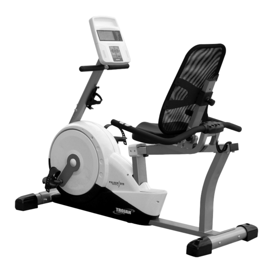
- Page 1 TROJAN ® P U L S E R 5 0 0 MY SPACE MY TIME R E C U M B E N T B I K E RECUMBENT CYCLE CARE INSTRUCTIONS AND ASSEMBLY MANUAL CAUTION READ ALL PRECAUTIONS AND...
-
Page 2: Table Of Contents
INDEX PAGE SAFETY INSTRUCTIONS PRE ASSEMBLY CHECK LIST ASSEMBLY STEPS COMPUTER FUNCTIONS FITNESS TIPS & TECHNIQUES CONDITIONING GUIDELINES WARM -UP AND COOL-DOWN FREQUENTLY ASKED QUESTIONS PARTS LIST 10. EXPLODED DRAWING 11. TROJAN 1 YEAR LIMITED WARRANTY 12. TROJAN REPAIRS PROCEDURE... -
Page 3: Safety Instructions
1. SAFETY INSTRUCTIONS WARNING : To reduce the risk of serious injury, read the following safety instructions before using the TROJAN PULSER 500 BIKE. 1. Use the TROJAN PULSER 500 BIKE only on a level surface. 2. Keep children and pets away from this equipment at all times. -
Page 4: Pre Assembly Check List
2. PRE ASSEMBLY CHECK LIST Thank you for choosing the TROJAN PULSER 500 BIKE. We take great pride in producing this quality product and hope it will provide many hours of quality exercise to make you feel better, look better and enjoy life to its fullest. -
Page 5: Assembly Steps
3. ASSEMBLY STEPS STEP 01 • Securely fasten the Front Stabiliser assembly (J) to the Base assembly using 2 Carriage Bolts (I-1), 2 Flat Washers (I-3), and 2 Acorn Nuts (I-2). Note: The transport wheels should be facing outward. • Securely fasten the Rear Stabiliser assembly (K) to the back of the Base assembly using 2 Carriage Bolts (I-1), 2 Flat Washers (I-3), and 2 Acorn Nuts (I-2) 1064M-5... - Page 6 ASSEMBLY STEPS STEP 02 • Attach the Left Pedal (D-L) to the Left Crank Arm on the Base assembly. Thread the pedal onto the crank arm and securely tighten in place using the pedal wrench. Note: A counterclockwise rotation will tighten the pedal to the crank arm and a clockwise rotation will loosen the pedal.
- Page 7 STEP 03 • Mount the Seat Pad (F-4) to the Seat Slider (F) using 4 Truss Head Bolts (I-4) and 4 Flat Washers (I-5) • Attach the Handlebar Assembly (H) to rear mounting plate of Seat Slider (F) using 4 Truss Head Socket Bolts (I-6) and 4 Flat Washers (I-5).
-
Page 8: Assembly Steps
STEP 05 • Connect the Upper Computer Cable (B-1) to the Lower Computer Cable (L) • Connect the Upper Pulse Cable assembly (B-6) to the Lower Pulse Cable assembly (C-21). • Tuck the excess cable lengths into the frame tubing and slide the Handlebar Post (B) down on to the Main Frame (C). -
Page 9: Computer Functions
4. COMPUTER FUNCTIONS FUNCTIONS No preset target.Time will count up from 00:00 to 99:59 (maximum) Count up where each increment is 1 second. TIME If training with a preset Time. Time will count down from preset time to Count down 00:00.Each preset increment or decrement is 1 minute between 1:00 to 99:00 minutes. - Page 10 COMPUTER FUNCTIONS OPERATING INSTRUCTION Power on, Connect the adaptor to the computer to power on. The LCD screen will display all segments and sound a long beep while showing the wheel diameter (78”) for 2 seconds (drawing 1). drawing 1 PROGRAMMING MODE 1.
- Page 11 COMPUTER FUNCTIONS 1.5 Press RESET button to return to training mode selection on the main menu. Program selections are MANUAL, PROGRAM, H.R.C. (Heart Rate Control), USER,WATT. Press UP and DOWN to select the program you want and press START for QUICK START in Manual mode. (drawing 7-10) drawing 7 drawing 8 drawing 9...
- Page 12 COMPUTER FUNCTION H.R.C. MODE (HEART RATE CONTROL) After entering H.R.C. mode, press the UP and DOWN button to select a different target from 55%, 75%, 90% and TARGET. Press MODE to confirm. (drawing 13) drawing 13 Note: 55% - Fat Burning Zone. (Exercise at this level for a minimum of 30 minutes at a time) 75% - Cardio Vascular Zone;...
-
Page 13: Fitness Tips & Techniques
5. FITNESS TIPS AND TECHNIQUES AEROBIC EXERCISE Aerobic exercise is any sustained activity that sends oxygen to your muscles via your heart and lungs. Aerobic exercise improves the fitness of your lungs and heart - your body’s most important muscle. Aerobic exercise fitness is promoted by any activity that uses your large muscle -arms, legs, or buttock, for example. -
Page 14: Conditioning Guidelines
6. CONDITIONING GUIDELINES How you begin your exercise program depends on your physical condition. If you have been inactive for several years, or are severely overweight, you must start slowly and increase your time on the equipment; a few minutes per workout. Initially, you may be able to exercise only for a few minutes in your target zone, however, your aerobic fitness will improve over the next six to eight weeks. -
Page 15: Warm-Up And Cool-Down
7. WARM-UP AND COOL-DOWN WORKOUT GUIDELINES Each workout should include the following three parts: A warm-up, consisting of 5 to 10 minutes of stretching and light exercise. A proper warm-up increases your body tem- perature, heart rate, and circulation in preparation for exercise. Training zone exercise, consisting of 20 to 30 minutes of exercising with your heart rate in your training zone. -
Page 16: Frequently Asked Questions
8. FREQUENTLY ASKED QUESTIONS Q1. My computer consol is not working 1. Check that your power cord is in your power outlet and is on. 2. Check that you have a power supply to your home. 3. Ensure that the consol computer cables have been connected properly in the neckpiece when assembling the unit. Q2. -
Page 17: Parts List
9. PARTS LIST Description Q’ty Description Q’ty Computer 1PCS Seat back frame 1PCS Truss screw M5x10L 4PCS Adjusting knob for seat slider 1PCS Handlebar post 1PCS Adjusting knob for adjustable seat back frame 1PCS Upper computer cable 4PCS Cap for seat slider 4PCS Truss head socket bolts 4PCS... -
Page 18: Exploded Drawing
10. EXPLODED DRAWING 1064M-18... - Page 19 EXPLODED DRAWING 1064M-19...
-
Page 20: Trojan 1 Year Limited Warranty
11. TROJAN 1 YEAR LIMITED WARRANTY Masstores (Pty)Ltd (“the Supplier”) hereby provides a limited warranty to the original purchaser of this product (“the Consumer”) that this product will be free of manufacturing defects in materials and workmanship which under normal,... -
Page 21: Proof Of Purchase
The Consumer does not need to return the product to the store. The Consumer shall phone the Trojan hotline on 0861 Trojan (0861 876 526) and the Supplier’s authorized agent will at its discretion either repair the item at the Consumer’s residence or collect and repair the item at their premises. -
Page 22: Trojan Repairs Procedure
12. TROJAN REPAIRS PROCEDURE 1. Procedure for repairs Should you experience any faults or breakdowns on your Trojan equipment, please adhere to the following procedure to have the fault rectified speedily and professionally. • Do not return the product to the store* Call 0861 Trojan (0861 876526) to log the faulty product (under warranty or out of warranty) •...
Need help?
Do you have a question about the PULSER 500 and is the answer not in the manual?
Questions and answers