Table of Contents
Advertisement
Quick Links
Advertisement
Table of Contents

Related Manuals for Life Gear 20296


Summary of Contents for Life Gear 20296
- Page 1 EVOKE, MAGNETIC UPRIGHT BIKE ITEM NO: 20296 OWNER’S MANUAL IMPORTANT: Read all instructions carefully before using this product. Retain this owner’s manual for future reference. The specifications of this product may vary from this photo, subject to change without notice.
-
Page 2: Table Of Contents
TABLE OF CONTENTS WARRANTY ------------------------------------------------------------------------------- 2 IMPORTANT SAFETY INSTRUCTIONS ------------------------------------------- 3 PARTS LIST ------------------------------------------------------------------------------- 4 HARDWARE PACKING LIST --------------------------------------------------------- 5 TOOLS -------------------------------------------------------------------------------------- 5 OVERVIEW DRAWING ----------------------------------------------------------------- 6 ASSEMBLY INSTRUCTIONS --------------------------------------------------------- 7 OPERATING THE COMPUTER ------------------------------------------------------ 11 ADJUSTMENTS -------------------------------------------------------------------------- 13 MAINTENANCE -------------------------------------------------------------------------- 15 TROUBLESHOOTING ------------------------------------------------------------------ 15 WARM UP AND COOL DOWN ROUTINE ----------------------------------------- 16... -
Page 3: Warranty
ONE YEAR LIMITED WARRANTY LifeGear Inc. warrants to the original purchaser that this product is free from defects in material and workmanship when used for the purpose intended, under the conditions that it has been installed and operated in accordance with LifeGear's Owner's Manual. LifeGear's obligation under this warranty is limited to replacing or repairing free of charge, any parts which may prove to be defective under normal home use. -
Page 4: Important Safety Instructions
IMPORTANT SAFETY INSTRUCTIONS Basic precautions should always be followed, including the following important safety instructions when using this equipment: Read all instructions before using this equipment. Read all instructions and follow it carefully before using this equipment. Make sure the equipment is properly assembled and tightened before use. -
Page 5: Parts List
PARTS LIST Description Qty No. Description 001 Main Frame 1 030 Curve Washer Ø10 002 Handlebar Ø25 1 031 Cap Nut M10 003 Handlebar Post Ø50 1 032 Rear Stabilizer End Cap Ø50 004 Rear Stabilizer Ø50 1 033 Front Stabilizer End Cap Ø50 005 Seat Post Ø38 1 034 Bolt M6x48 006 Front Stabilizer Ø50... -
Page 6: Hardware Packing List
PARTS LIST Description Qty No. Description 059 Nut M6 2 064 Seat Post Cover 060 Sensor with Wire L=1100mm 1 065 Left Cover 061 Screw ST2.9x10 2 066 Right Cover 062 Seat Post Knob M12 1 067 Cover Cap Ø40xØ25x10 063 Seat Post Bushing 1 068 Screw ST4.2x25 HARDWARE PACKING LIST... -
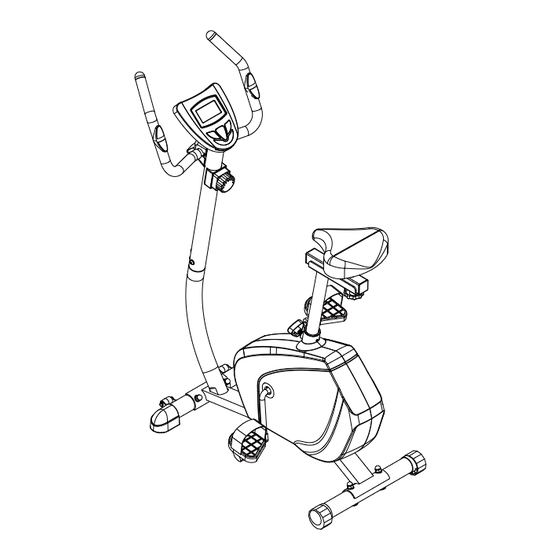
Page 7: Overview Drawing
OVERVIEW DRAWING... -
Page 8: Assembly Instructions
ASSEMBLY INSTRUCTIONS Tool: Multi Hex Tool S10, S13, S17, S19 1. Front/Rear Stabilizers and Right/Left Foot Pedals Installation Position the Front Stabilizer (6) in front of the Main Frame (1) and align bolt holes. Attach the Front Stabilizer (6) onto the front curve of the Main Frame (1) with two M10x57 Carriage Bolts (29), two Ø10 Curve Washers (30), and two M10 Cap Nuts (31). - Page 9 Tool: Multi Hex Tool with Phillips Screwdriver S10, S13, S14, S15 2. Seat Post, Seat Cushion, and Seat Sliding Tube Installation Insert the Seat Post (5) into the Seat Post Bushing (63) on the tube of the Main Frame (1) and then attach the M12 Seat Post Knob (62) onto the tube of the Main Frame (1) by turning it in a clockwise direction to lock the Seat Post (5) in the suitable position.
- Page 10 Tool: Allen Wrench S6 Multi Hex Tool with Phillips Screwdriver S10, S13, S14, S15 3. Handlebar Post and Tension Control Knob Installation Remove four M8x15 Bolts (38) and four Ø20xØ8 Curve Washers (37) from the Main Frame (1). Remove bolts with the S6 Allen Wrench provided. Insert the Tension Cable (27) through into the bottom hole of Handlebar Post (3) and pull it out from the square hole of Handlebar Post (3).
- Page 11 Tool: Multi Hex Tool with Phillips Screwdriver S10, S13, S14, S15 4. Handlebar and Computer Installation Insert the Hand Pulse Sensor Wires (18) into the hole on the Handlebar Post (3) and then pull them out from the top end of the Handlebar Post (3). Place the Handlebar (2) through clamp on the Handlebar Post (3) with hand pulse sensors facing the seat.
-
Page 12: Operating The Computer
OPERATING THE COMPUTER SPECIFICATIONS: TIME --------------------------------------------------- 0:00-99:59 MIN: SEC SPEED ------------------------------------------------ 0.0-999.9 KM/H DIST (DISTANCE) ---------------------------------- 0.0-999.9 KM CAL (CALORIES) ----------------------------------- 0.0-999.9 KCAL ODO (ODOMETER) -------------------------------- 0-9999 KM PULSE ------------------------------------------------- 40-240 BEATS/MIN BUTTON FUNCTIONS: MODE: Press the MODE button to select each function of computer. Press and hold the MODE button for 3 seconds, all data values will clear to zero except the ODO (ODOMETER) data values. - Page 13 PULSE: Press the MODE button until the arrow points to the PULSE, the computer will display your current heart rate figures after you hold both two hands on handlebar grip sensors. To ensure the pulse readout is more precise, please always hold on to the handlebar grip sensors with two hands instead of just with one hand only when you try to test your heart rate figures.
-
Page 14: Adjustments
ADJUSTMENTS Adjusting the Tension Control Knob To increase the load, turn the tension control knob in a clockwise direction. To decrease the load, turn the tension control knob in a counterclockwise direction. Tension Control Knob Adjusting the Handlebar Hold the handlebar while loosening the handlebar T-Knob. Adjust the handlebar to the desired position and turn the handlebar T-Knob in a clockwise direction to tighten. - Page 15 Adjusting the Seat Height Turn the seat post knob in a counterclockwise direction until the seat post can be slid up or down and then slide the seat post up or down direction to the suitable position. Lock the seat post in place by tightening the seat post knob in a clockwise direction.
-
Page 16: Maintenance
MAINTENANCE Cleaning The upright bike can be cleaned with a soft cloth and mild detergent. Do not use abrasives or solvents on plastic parts. Please wipe your perspiration off the upright bike after each use. Be careful not get excessive moisture on the computer display panel as this might cause an electrical hazard or electronics to fail. -
Page 17: Warm Up And Cool Down Routine
WARM UP AND COOL DOWN ROUTINE A good exercise program consists of a warm-up, aerobic exercise, and a cool down. Do the entire program at least two to three times a week, resting for a day between workouts. After several months you can increase your workouts to four or five times per week. AEROBIC EXERCISE is any sustained activity that sends oxygen to your muscles via your heart and lungs. - Page 18 SIDE STRETCHES Open your arms to the side and lift them until they are over your head. Reach your right arm as far toward the ceiling as you can for one count. Repeat this action with your left arm. QUADRICEPS STRETCH With one hand against a wall for balance, reach behind you and pull your right foot up.
- Page 19 TOE TOUCHES Slowly bend forward from your waist, letting your back and shoulders relax as you stretch toward your toes. Reach as far as you can and hold for 15 counts. HAMSTRING STRETCHES Extend your right leg. Rest the sole of your left foot against your right inner thigh.
Need help?
Do you have a question about the 20296 and is the answer not in the manual?
Questions and answers