Sign In
Upload
Manuals
Brands
Nilfisk-Advance Manuals
Scrubber
56414021
Nilfisk-Advance 56414021 Scrubber Parts Manuals
Manuals and User Guides for Nilfisk-Advance 56414021 Scrubber Parts. We have
1
Nilfisk-Advance 56414021 Scrubber Parts manual available for free PDF download: Service Manual
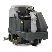
Nilfisk-Advance 56414021 Service Manual (213 pages)
SC6500 Series
Brand:
Nilfisk-Advance
| Category:
Scrubber
| Size: 14.23 MB
Table of Contents
Service Manual
1
Table of Contents
2
General Information
9
General Machine Description
9
Service Manual Purpose and Application
9
Conventions
9
Feedback
9
Revision History
9
Other Manuals and Information Sources
9
Electronic Databases
9
Manuals
9
Parts and Service
10
Nameplate
10
Transporting the Machine
10
Towing
11
Caution and Warning Symbols
11
General Safety Instructions
11
Emergency-Stop Switch/Battery Disconnect
13
Technical Specifications (as Installed and Tested on the Unit)
14
Advance Brand SC6500 Models
14
Nilfisk Brand SC6500 Models
16
Dimensions
18
General Machine Overview
19
Major Machine Components
19
Control Panel
21
Switch and Button Functions
21
Control Panel Indicators
24
Control Panel Display
26
Caution Displays
26
Circuit Breakers
27
General Maintenance
27
Maintenance after Use
27
Maintenance Schedule
28
Machine Lubrication
29
Lubrication Points
29
PM Check List - SC6500
30
Chassis System
32
Major Chassis Components
32
Control System
33
Functional Description
33
Overview
33
A2 Control Board Assembly
33
A3 Switch/Display Panel Assembly
34
Circuit Description
34
Main Control Programming Options
34
Fault Recall Mode
34
To Select the Battery Used in the Machine
35
To Restore the Scrub Pressures to the Factory Default Settings
35
To Enable/Disable the Fault Detection
35
To Display the Control Board Revision Level
36
Monitor Mode
36
Scrub Deck down Time Adjustment
36
Normal (Light) Scrub Setting Adjustment
37
Heavy Scrub Setting Adjustment
38
Extreme Scrub Setting Adjustment
38
Scrub Speed Switch Lockout
39
Detergent System Selection Mode
40
Ecoflex ™ Mode Selection
40
Vacuum Motor Configuration Option
40
Recovery Tank Full Detection Enable/Disable
41
Solution Flow in Reverse Enable/Disable
41
Indicator LED Intensity Selection Option
42
Detergent and Solution Pump Purge
42
Method 1
42
Method 2 (as Described in the Instructions for Use)
42
Side Broom Function
43
Side Broom Height Adjustment
43
Display Mode Selection
44
Service Test Mode
44
To Enter the Service Test Mode
44
Service Test Mode Display
44
Control Panel Switch and Button Functions
45
Troubleshooting
46
Error Indicator and Error Code Display
46
Error Codes
47
Removal and Installation
53
A2 Control Board Assembly
53
Specifications
54
I/O Table with Shop Measurements
55
A2 Control Board Assembly
55
Electrical System
59
Functional Description
59
Overview
59
Low-Voltage Cut-Out Feature
59
Battery Condition Indicator
59
Component Locations
61
Battery Location
63
Connector Pin-Outs
64
J1 Connects to A2 Control Board
64
J2 Connects to A2 Control Board
65
J3 Connects to A3 Display Panel
65
X6 Connects to A1 Speed Controller
66
X7 Connects to Drive Motor
67
X8 Connector for Curtis Programmer
67
X10
67
X12 Connects to H2 Flashing Lamp X11
68
X13 Connects to M12 Solution Control Pump X14
68
X16 Connects to L1 Solution Solenoid Valve X15
68
X20 Connects to M3 Squeegee Actuator X19
69
X29 Connects to M7 Left Side Broom Motor X27
70
X30 Connects to M8 Right Side Broom Motor X28
70
X32
70
X41 Connects to R2 Scrub Deck Sensing Resistor X40
71
X43 Connects to S5 Solution Tank Float Switch X42
71
X49 Connects to X48 Connector of Vacuum Motor Wiring Harness
71
X51
72
X55 Connects to M15 Accessory Pump (Optional) X54
72
X59 Connects to Telematics Connector Jumper X59A
72
X59A Telematics Connector Jumper
73
X60 (Deutsch DTM04-6P) Connects to X61
73
X61 (Deutsch DT M06-6S)Connects to X60
73
Maintenance and Adjustments
74
Wet-Cell Battery Maintenance
74
Checking the Battery Water Level
74
Charging Wet-Cell Batteries
74
To Charge the Batteries
75
When Servicing Batteries
75
Troubleshooting
76
Battery Testing
76
General Troubleshooting
76
Removal and Installation
77
To Install the Batteries
77
Specifications
79
Special Tools
79
Wiring Diagram Tips
80
Wiring Diagram PN 56414095 REV C Sheet 1 of 3
82
Wiring Diagram PN 56414095 REV C Sheet 2 of 3
83
Wiring Diagram PN 56414095 REV C Sheet 3 of 3
84
Wiring Harness Diagram 56414096_REV_C
85
Options and Accessories
86
Recovery System
90
Functional Description
90
Overview
90
Recovery Tank
90
Vacuum Motor
90
Squeegee and Squeegee Hose
90
Float Cage and Ball
91
Recovery System Wiring Diagram
91
Circuit Description
92
Component Locations
92
Vacuum Motor and Vacuum Hose
92
Top Cover Assembly
93
Float Cage and Ball
93
Recovery Tank Lid
94
Squeegee and Drain Hoses
94
Maintenance
95
To Inspect and Clean the Vacuum Filter and Inlet Screen
95
To Inspect and Clean the Vacuum Motor Float Cage
95
Troubleshooting
96
Insufficient Water Pick-Up
97
Possible Causes
97
Troubleshooting Steps
97
Removal and Installation
99
Recovery Tank
99
Vacuum Motor
100
Specifications
102
Shop Measurements
102
K1 Vacuum Contactor
102
Vacuum Motor
102
Special Tools
102
Scrub System, Cylindrical
103
Functional Description
103
Overview
103
Cylindrical Scrub System Wiring Diagram
103
Circuit Description
104
Component Locations
105
Maintenance and Adjustments
106
General Scrub System Maintenance
106
Daily Maintenance
106
Weekly Maintenance
106
Monthly Maintenance
106
Scrub Brush Belt Replacement
106
Lift Actuator Adjustment
108
Using the Actuator Power Cord Adapter
108
Lift Actuator Drive Nut Adjustment
109
Side Skirt Replacement and Adjustment
113
Troubleshooting
114
Removal and Installation
116
Scrub Brushes
116
Scrub Brush Deck
117
Scrub Deck Lift Actuator
119
Scrub Brush Motor
120
Specifications
121
Shop Measurements
121
Brush Contactor (K2, K3 or K4)
121
Scrub Brush Motor
121
Brush Actuator Motor
122
Special Tools
122
Scrub System, Disc
123
Functional Description
123
Overview
123
Disc Scrub System Wiring Diagram
123
Circuit Description
124
Component Locations
125
Maintenance and Adjustments
126
Lift Actuator Adjustment
126
Using the Actuator Power Cord Adapter
126
Lift Actuator Drive Nut Adjustment
127
Side Skirt Replacement and Adjustment
131
Troubleshooting
132
Removal and Installation
134
Scrub Brush Deck
134
Scrub Deck Lift Actuator
135
Scrub Brush Motor and Gearbox
136
To Remove and Install a Gearbox Assembly
136
To Disassemble and Reassemble a Gearbox Assembly
136
Specifications
137
Shop Measurements
137
Scrub Brush Motor
137
Special Tools
138
Solution System
139
Functional Description
139
Overview
139
Solution Tank
140
Shutoff Valve
140
Drain Hose and Hose Cap
140
Solution Filter
140
Solution Control Pump
140
Solution Solenoid Valve
140
Solution Manifold (Disc Decks Only)
140
Accessory Pump
140
Detergent Tank and Pumps
141
Solution System Wiring Diagram
141
Circuit Description
141
Solution System
141
Detergent System
142
Accessory Pump
142
Component Locations
143
Shutoff Valve
143
Solution Level Switch
143
Drain Hose and Hose Cap
144
Solution Filter
144
Solution Control Pump
144
Solution Solenoid Valve
145
Solution Manifold (Disc Decks Only)
145
Accessory Pump
145
Detergent Tank and Pumps
146
Maintenance and Adjustments
147
To Disassemble and Clean the Solution Solenoid Valve
147
Weekly Maintenance
147
To Empty and Rinse the Solution Tank
147
To Clean the Solution Filter
147
To Clean the Solution Delivery Trough (Cylindrical Scrub Decks Only)
148
To Purge the Detergent System
148
To Purge the Detergent System When Changing Detergents
149
To Program the Detergent Ratio
149
Troubleshooting
150
Removal and Installation
152
Solution Control Pump
152
Solution Solenoid Valve
153
Specifications
154
Solution Flow Rates
154
Component Specifications
154
Shop Measurements
154
Squeegee System
155
Functional Description
155
Overview
155
Squeegee System Wiring Diagram
155
Circuit Description
155
Squeegee Lift Actuator Reverse Function
156
Component Locations
156
Maintenance and Adjustments
157
To Reverse or Replace the Rear Squeegee Wiping Blade
157
To Reverse or Replace the Front Squeegee Blade
157
Squeegee Adjustment
158
To Adjust the Squeegee Angle
158
To Adjust the Squeegee Blade Height
158
Lift Actuator Adjustment
159
Using the Actuator Power Cord Adapter
159
Actuator Drive Nut Adjustment
159
Troubleshooting
160
Removal and Installation
161
Squeegee Lift Actuator
161
Specifications
162
Shop Measurements
162
Squeegee Actuator Motor
162
Special Tools
162
Steering System
163
Functional Description
163
Drive Wheel Steering Assembly
163
Maintenance and Adjustments
164
Steering Chain
164
Removal and Installation
164
Steering Chain Removal and Tensioning
164
Sweep System, Side Broom
166
Functional Description
166
Overview
166
Side Broom Sweep System Wiring Diagram
166
Circuit Description
167
Component Locations
167
Maintenance and Adjustments
168
Side Broom Height Adjustment
168
Lift Actuator Adjustment
169
Using the Actuator Power Cord Adapter
169
Lift Actuator Drive Nut Adjustment
169
Troubleshooting
171
Removal and Installation
172
Side Broom Lift Actuator
172
Side Broom Gearmotor
173
Specifications
174
Shop Measurements
174
Side Broom Contactor (K6)
174
Side Broom Motor
174
Side Broom Actuator Motor
174
Special Tools
175
Wheel System, Non-Traction
176
Functional Description
176
Overview
176
Component Locations
176
Maintenance and Adjustments
177
Brake Cable Adjustment
177
Brake Caliper Pad Wear Adjustment
178
Troubleshooting
179
Removal and Installation
180
Brake Cable Replacement
180
Rear Wheel and Brake Caliper
181
Wheel System, Traction
182
Functional Description
182
Drive Pedal
182
Wheel Drive Controller
182
Drive Wheel Motor Assembly
182
Wheel Motor, Temp Sensor and Encoder
183
Circuit Description
184
Motor Temperature Sensor
185
Component Locations
187
Troubleshooting
188
Fault Codes
188
Summary of LED Display Formats
189
Fault Code Table (Troubleshooting Chart)
190
Troubleshooting Chart
190
Fault History
201
Removal and Installation
202
Front Drive Wheel/Tire Removal
202
Front Drive Wheel/Tire Installation
204
Wheel Drive Assembly
205
Potentiometer Testing
207
Drive Pedal Installation
207
Drive Pedal Neutral Adjustment and Pedal Replacement
207
Wheel Drive Controller Replacement
208
Specifications
208
General Specifications
208
Speed Mode Table
209
Specifications
210
Shop Measurements
210
Wheel Drive Controller Voltage Measurements
210
Low Current 35 Pin Connector (X6)
210
Motor U, V and W Terminal Pair Voltages
211
Motor U, V and W Terminal Pair Frequency
212
Wheel Speed Controller Current Draw
212
Main Contactor (K7)
212
Special Tools
213
Advertisement
Advertisement
Related Products
Nilfisk-Advance 56414020
Nilfisk-Advance 56414022
Nilfisk-Advance 56414023
Nilfisk-Advance 56414024
Nilfisk-Advance 56414025
Nilfisk-Advance 56414026
Nilfisk-Advance 56414010
Nilfisk-Advance 56414011
Nilfisk-Advance 56414013
Nilfisk-Advance 56414015
Nilfisk-Advance Categories
Vacuum Cleaner
Floor Machine
Scrubber
Pressure Washer
Blower
More Nilfisk-Advance Manuals
Login
Sign In
OR
Sign in with Facebook
Sign in with Google
Upload manual
Upload from disk
Upload from URL