Sharp AR-M236 Service Manual
Hide thumbs
Also See for AR-M236:
- Copier manual (100 pages) ,
- Key operator's manual (24 pages) ,
- Software setup manual (20 pages)
Table of Contents
Advertisement
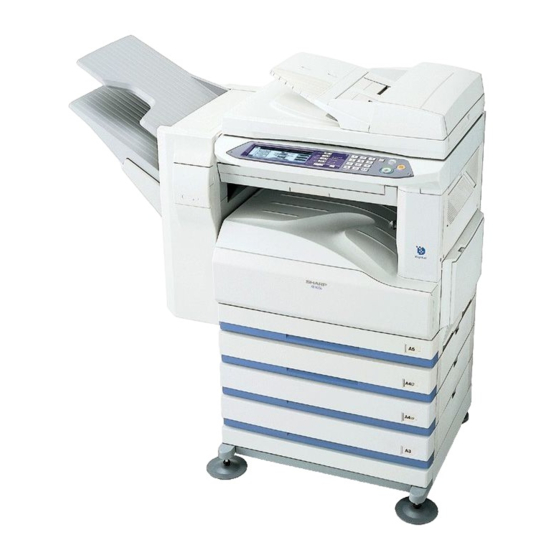
AR-M236/M276
AR-M237/M277
[1] NOTE FOR SERVICING . . . . . . . . . . . . . . . . . . . . . . . . . . . . . . . . 1-1
[2] SYSTEM CONFIGURATION . . . . . . . . . . . . . . . . . . . . . . . . . . . . . 2-1
[3] SPECIFICATIONS . . . . . . . . . . . . . . . . . . . . . . . . . . . . . . . . . . . . . 3-1
[4] CONSUMABLE PARTS . . . . . . . . . . . . . . . . . . . . . . . . . . . . . . . . . 4-1
[5] UNPACKING AND INSTALLATION . . . . . . . . . . . . . . . . . . . . . . . . 5-1
[6] EXTERNAL VIEW AND INTERNAL STRUCTURE . . . . . . . . . . . . 6-1
[7] ADJUSTMENTS, SETTING . . . . . . . . . . . . . . . . . . . . . . . . . . . . . . 7-1
[8] SIMULATION . . . . . . . . . . . . . . . . . . . . . . . . . . . . . . . . . . . . . . . . . 8-1
[9] TROUBLE CODE LIST. . . . . . . . . . . . . . . . . . . . . . . . . . . . . . . . . . 9-1
[10] DISASSEMBLY, ASSEMBLY AND MAINTENANCE . . . . . . . . . . 10-1
[11] OTHERS . . . . . . . . . . . . . . . . . . . . . . . . . . . . . . . . . . . . . . . . . . . . 11-1
[12] ELECTRICAL SECTION. . . . . . . . . . . . . . . . . . . . . . . . . . . . . . . . 12-1
Parts marked with "
" are important for maintaining the safety of the set. Be sure to replace these parts with
specified ones for maintaining the safety and performance of the set.
SERVICE MANUAL
DIGITAL MULTIFUNCTIONAL
SYSTEM
MODEL
CONTENTS
SHARP CORPORATION
CODE: 00ZARM277/A1E
AR-M236/M276
AR-M237/M277
This document has been published to be used
for after sales service only.
The contents are subject to change without notice.
Advertisement
Table of Contents

Related Manuals for Sharp AR-M236


Summary of Contents for Sharp AR-M236
-
Page 1: Table Of Contents
SERVICE MANUAL CODE: 00ZARM277/A1E DIGITAL MULTIFUNCTIONAL SYSTEM AR-M236/M276 AR-M236/M276 AR-M237/M277 MODEL AR-M237/M277 CONTENTS [1] NOTE FOR SERVICING ....... . 1-1 [2] SYSTEM CONFIGURATION . - Page 2 2. Self diagnostics........9-2 8. “Sharp Printer Language with Compression (SPLC)”...
-
Page 3: Note For Servicing
8) The machine has got sharp edges inside. Be careful not to dam- CAUTION: If this CAUTION should be ignored, an injury or a age fingers when servicing. -
Page 4: Product Line And Options
AR-PK1/N AR-PF1 AR-PF2 Printer expansion kit PS3 expansion kit Bar code font kit Flash ROM kit AR-SM5 AR-NC5J AR-NS2 256MB expansion memory board Print server card Network scanner expansion kit AR-SM6 512MB expansion memory board AR-M236/M276/M237/M277 CONFIGURATION 2 - 1... -
Page 5: C. Combination Of Options List
(From July 2003 board onward) 512MB expansion memory AR-SM6 board Software Network scanner expansion kit AR-NS2 The memory of 128MB must be added. For details of the options, refer to the Service Manual of each option. AR-M236/M276/M237/M277 CONFIGURATION 2 - 2... -
Page 6: Specifications
11" × 17" 8-1/2" × 14" 8-1/2" × 13" 8-1/2" × 11" 13.5 13.5 (Horizontal feed) 8-1/2" × 11" (Vertical feed) A5/INV 13.5 13.5 ∗ The slowest speed is listed in enlargement/reduction copy. ∗ Single-side copy AR-M236/M276/M237/M277 SPECIFICATIONS 3 - 1... -
Page 7: Engine Specifications
Function This exit tray is set up above main exit tray, and can separate copier exit, printer exit and FAX exit. e. Many of tray 1 (this tray can not set up more than 2) AR-M236/M276/M237/M277 SPECIFICATIONS 3 - 2... -
Page 8: C. Optical (Image Scanning) Section
(5) Original size/Scanning area Pressure roller Silicone rubber roller with re-engerized cube a. Max. original size Separation system Natural separation (with pawl) A3 paper (11" × 17") G. Drive Drive section Motor Main motor DC brushless motor AR-M236/M276/M237/M277 SPECIFICATIONS 3 - 3... -
Page 9: Functions
Yes (Standard) Total counter Toner save Department Yes (100 departments) management Job registration/call Yes (10 jobs) Cover paper Yes (Insertion and stapling must be allowed from manual feed.) OHP insert paper Yes (Only printer function) AR-M236/M276/M237/M277 SPECIFICATIONS 3 - 4... -
Page 10: Environment Conditions
(6) Standard temperature and humidity (Depending on conditions of the machine Temperature 20 to 25°C and option installation.) Duplex print Standard Humidity 65±5%RH Finisher Option Printer driver Standard Manual (Online Standard manual) Platform IBM PC/AT (Include compatible machine) AR-M236/M276/M237/M277 SPECIFICATIONS 3 - 5... -
Page 11: B. Printer Driver Specification
Yes / No Toner save Yes / No Photo Enhancement Yes / No Fit to Page Yes / No 2 Gradation print Yes / No Image Adjustment Brightness : 0 to 100 Contrast : 0 to 100 AR-M236/M276/M237/M277 SPECIFICATIONS 3 - 6... - Page 12 4680 4780 Executive 4350 6300 4050 4150 (6) Print enable area COM-10 2474 5700 2174 2274 3826 5408 3542 3626 2598 5196 2314 2398 Actual page size Print area Logic paper size HP/GL picture frame AR-M236/M276/M237/M277 SPECIFICATIONS 3 - 7...
-
Page 13: C. Interface
IEEE1284 Page memory custom size, the left margin is set according to the default paper size. Header + JBIG data JBIG- ASIC Lite Extraction Compressed JBIG printer driver memory Data through : Data flow AR-M236/M276/M237/M277 SPECIFICATIONS 3 - 8... -
Page 14: Consumable Parts
×3 3000 staples AR-SC1 For AR-FN5N (For 30 sheets staple) ×3 11 Transfer roller unit Transfer roller unit ×1 150K AR-272TX ∗ The other maintenance parts than the above are supplied as service parts. AR-M236/M276/M237/M277 CONSUMABLE PARTS 4 - 1... -
Page 15: C. Stcl/Srh/Srs/Srssc/Sbi/Agent
Drum and Drum fixing plate. 10 Staple cartridge Staple cartridge ×3 3000 staples AR-SC1 For AR-FN5N (For 30 sheets staple) ×3 ∗ The other maintenance parts than the above are supplied as service parts. AR-M236/M276/M237/M277 CONSUMABLE PARTS 4 - 2... -
Page 16: Production Number Identification
The production month. X stands for October, Y November, and Z December. 4. Life (packed conditions) The production sub lot. Photoconductor drum (36 months from the production month) Developer, toner (24 months from the production month) AR-M236/M276/M237/M277 CONSUMABLE PARTS 4 - 3... -
Page 17: Unpacking And Installation
• Avoid installation to a place of poor ventilation. C. Transport • When transporting the machine, use manpower of two persons to hold the grips on the both sides of the machine with both hands. AR-M236/M276/M237/M277 UNPACKING AND INSTALLATION 5 - 1... -
Page 18: D. Other Precautions
• When disconnecting the power plug from the power outlet, do not pull the cord. • Do not throw toner or the toner cartridge into a fire. • Keep toner or the toner cartridge away from the children. AR-M236/M276/M237/M277 UNPACKING AND INSTALLATION 5 - 2... -
Page 19: Developer Cartridge Installation
2) Loosen the blue screw and pull out the developing cartridge. 3) Remove the developer tank from the developer cartridge. ∗ Dirt or dust must be removed from the toner cartridge before installing. AR-M236/M276/M237/M277 UNPACKING AND INSTALLATION 5 - 3... -
Page 20: Toner Density Sensor Level Adjustment
The tray settings screen will appear. TOT L COUNT CONTRA 4) Touch the [BYPASS TRAY] key. ADDRES TRAY SETTINGS CONTRO TYPE / SIZE TRAY 4 PLAIN / 11x17 KEYBOARD SELECT BYPASS PLAIN TRAY AR-M236/M276/M237/M277 UNPACKING AND INSTALLATION 5 - 4... -
Page 21: Installation Of Options
1) Remove the shielding plate. PCL PWB Remove five screws and remove the shielding plate. M3 screws with spring washer 4) Attach the shielding plate. Attach the shielding plate using five screws. Screws Screws Screws Screws AR-M236/M276/M237/M277 UNPACKING AND INSTALLATION 5 - 5... -
Page 22: System Configuration
1) Remove the shielding plate. Remove five screws and remove the shielding plate. To enable the PS3, the product key must be acquired. (For the method of acquiring the product key, contact the SHARP authorized dealer.) 1) Check that AR-P17 operates normally. -
Page 23: D. Ar-Nc5J
Code39QuarterInch-Regular 20 Upc-HalfMusic Code39SmallHigh-Regular 21 Upc-HalfNarrow Code39Slim-Regular 22 Upc-HalfThin Code39SmallLow-Regular 23 Upc-Tall-Regular 10 Code39SmallMedium-Regular 24 Upc-TallBarsThin-regular 11 Code39Wide-Regular 25 Upc-TallMusicThin-Regular Screws 12 Codabar-Regular 26 Upc-TallNarrow-Regular 13 Interleaved2of5-Regular 27 Upc-TallThin-regular 14 Interleaved2of5-Thin-Regular 28 ZipCodeBarcode-Regular AR-M236/M276/M237/M277 UNPACKING AND INSTALLATION 5 - 7... -
Page 24: E. Ar-Ns2
For the mounting method and the memory capacity, see below. To enable the scanner function, the product key must be acquired. (For the method of acquiring the product key, contact the SHARP autho- rized dealer.) 1) Check the capacity of the Printer PWB memory. -
Page 25: F. Ar-Sm5/Sm6
Attach the SDRAM memory module to CN1 and CN2 of the IMC board. When only one SDRAM memory module is used, attach it to CN1. Memory module (S.O.DIMM) 3) Reattach the shielding plate. Reattach the shielding plate using the five screws. Screws Screws AR-M236/M276/M237/M277 UNPACKING AND INSTALLATION 5 - 9... -
Page 26: External View And Internal Structure
Regular paper and special paper (such as transparency film) can be fed from the bypass tray. Bypass tray extension Pull out the bypass tray extension before placing paper in the bypass tray. AR-M236/M276/M237/M277 EXTERNAL VIEW AND INTERNAL STRUCTURE 6 - 1... -
Page 27: B. Internal Structure
• DATA indicator: Blinks when a fax has been received to memory and lights steadily when a fax is waiting in memory for transmission. [JOB STATUS] key Press to display the current job status. AR-M236/M276/M237/M277 EXTERNAL VIEW AND INTERNAL STRUCTURE 6 - 2... -
Page 28: D. Job Status Screen
[DETAIL] key Shows information on the selected job. This cannot be used for a received fax and copy. AR-M236/M276/M237/M277 EXTERNAL VIEW AND INTERNAL STRUCTURE 6 - 3... -
Page 29: E. Motor, Solenoid, Clutch
Manual feed tray tray empty sensor 1 position detection Manual feed length MPLD1 Manual feed paper detection sensor 1 length detection Manual feed length MPLD2 Manual feed paper detection sensor 2 length detection AR-M236/M276/M237/M277 EXTERNAL VIEW AND INTERNAL STRUCTURE 6 - 4... -
Page 30: H. Section
Puts toner on the OPC drum. PCL PWB 2nd/3rd mirror unit Reflects the images from the copy Tray interface PWB 2nd tray control lamp unit to the lens unit. DC power supply PWB DC voltage control AR-M236/M276/M237/M277 EXTERNAL VIEW AND INTERNAL STRUCTURE 6 - 5... -
Page 31: Adjustments, Setting
When inserting a thickness gauge, be careful not to scratch the developing doctor and the MG roller. <Adjustment specification> Developing doctor gap +0.1mm F/R both ends (20mm from the both ends):1.5 -0.15mm +0.15mm C (Center)(150mm from the both ends): 1.55 -0.2mm AR-M236/M276/M237/M277 ADJUSTMENTS 7 - 1... -
Page 32: B. Mechanism Section
3) Press the [P] key. The display is shifted to the copy menu. Min. unit: –25V increment 4) Select the paper feed tray, the print density, and the duplex mode. Enter the adjustment value with the 10-key. AR-M236/M276/M237/M277 ADJUSTMENTS 7 - 2... - Page 33 1 – 4mm void shift less Image loss: 3mm Print start 50-5 99 – H/0.127 or less position (2) SPF (RSPF) image lead edge position adjustment 1) Set a scale on the OC table as shown below. AR-M236/M276/M237/M277 ADJUSTMENTS 7 - 3...
- Page 34 (Main cassette) DEN-A-MANUAL Lead edge cancel 1-99 adjustment (Manual feed cassette) DEN-A-OPTION Lead edge cancel 1-99 adjustment (Option cassette) DEN-A-DUPLEX Lead edge cancel 1-99 adjustment (back of the machine) DEN-B Rear edge void adjustment 1-99 AR-M236/M276/M237/M277 ADJUSTMENTS 7 - 4...
- Page 35 3 mirror base unit are brought into contact with the positioning plate at the same time, the mirror base unit parallelism is proper. If one of them is in contact with the positioning plate, perform the adjustment of 4). AR-M236/M276/M237/M277 ADJUSTMENTS 7 - 5...
- Page 36 4) – 7). 10mm 10mm White paper 2) Make a normal (100%) copy of the test sheet on A3 (11" x 17") paper. (Fit the paper edge and the glass holding plate edge.) AR-M236/M276/M237/M277 ADJUSTMENTS 7 - 6...
- Page 37 CCD unit is properly installed and that OC mode adjustment in ratio adjustment (SIM 48-1) copying has been completed. Note: Before performing this adjustment, be sure to check that the CCD unit is properly installed. AR-M236/M276/M237/M277 ADJUSTMENTS 7 - 7...
- Page 38 Check that the CCD harness is properly inserted into the MCU con- (See the figure below.) nector. • When the display is 281 or above: 1) Remove the table glass. 2) Remove the dark box. AR-M236/M276/M237/M277 ADJUSTMENTS 7 - 8...
-
Page 39: C. Image Density (Exposure) Adjustment
TEXT (TONER "7" is copied. SAVE) "3" is copied. Placing the black chart "2" is copied. The black chart must cover this area. TEXT PHOTO "6" is copied. (TONER SAVE) "3" is copied. "2" is copied. AR-M236/M276/M237/M277 ADJUSTMENTS 7 - 9... -
Page 40: Simulation
1) Touch [OK] button. 2) Touch another selected item to change the selection state. 3) If all the list of the adjustment items cover two or more pages, touch [↑] and [↓] button to shift the page. AR-M236/M276/M237/M277 SIMULATION 8 - 1... - Page 41 (Other modes) The display is made according to the selected mode and the item. Do you want to change the content ? Enter the new setting and adjustment values. AR-M236/M276/M237/M277 SIMULATION 8 - 2...
-
Page 42: Simulation Code List
(low mode) in each printer Used to reset the developer counter. (The mode and the control circuit. developer counter of the DV unit which is installed is reset.) Used to clear the copy counter. AR-M236/M276/M237/M277 SIMULATION 8 - 3... - Page 43 Used to set the exposure correction value of SPF/ (U7-00) detection Yes/No. RSPF for OC exposure. Used to set the tag number. Used to set the AE and the limit value in AE (Toner save). AR-M236/M276/M237/M277 SIMULATION 8 - 4...
- Page 44 This adjustment is performed after the lens unit is Network Scanner Application. replaced. Used to check the network connection when the Used to check the operation of the printer function scanner option is installed. (auto print operation). AR-M236/M276/M237/M277 SIMULATION 8 - 5...
-
Page 45: Details
The motor for 10sec, the solenoid ON for 500msec, OFF for 500msec. original size. (20 times) 1. Select the desired item, and press the [START] key. 2. Enter the set value with the 10-key, and press the [START] key. AR-M236/M276/M237/M277 SIMULATION 8 - 6... - Page 46 Paper size of the rear edge guide Purpose Operation test/check adjustment value number plate Function Used to check the operation of the load in the finisher (Purpose) and the control circuit. Section Finisher Item Operation AR-M236/M276/M237/M277 SIMULATION 8 - 7...
- Page 47 Shifter home position (At detection, highlighted) STAPLE DOWN Tray descending 0-12 distance after staple paper exit Used to adjust the offset tray descending distance after staple paper exit. The descending distance is the relative distance from the non-staple standby position. AR-M236/M276/M237/M277 SIMULATION 8 - 8...
- Page 48 3rd cassette paper feed clutch TRC3 3rd cassette transport roller clutch LUM4 4th cassette lift-up motor CPFC4 4th cassette pick-up solenoid CPFS4 4th cassette paper feed clutch Note: Execution is possible only when the option cassette is installed. AR-M236/M276/M237/M277 SIMULATION 8 - 9...
- Page 49 Note: In SIM 7-1, pressing [CA] key terminates the simulation and the machine enters the aging mode without resetting. Therefore, to perform "4. Intermittent setup," the intermittent cycle must be set with SIM 7-6 in advance. AR-M236/M276/M237/M277 SIMULATION 8 - 10...
- Page 50 ) Linked with the destinations of SIM 26-6. control circuit. Linked with the auto exposure mode of SIM 46-19-1. Section Image process (Photoconductor/Developing/Transfer/ Set value Grid High Grid Low Cleaning) –480V –350V Developer/Toner hopper –505V –375V –530V –400V AR-M236/M276/M237/M277 SIMULATION 8 - 11...
- Page 51 *1. The negative value of the set value corresponds to the grid high output voltage. *2. The set values can be selected from the above 8 patterns only. *3. The selected pattern determines the grid high voltage and the grid low voltage. AR-M236/M276/M237/M277 SIMULATION 8 - 12...
- Page 52 Output is made with the entered value for 30sec. and the display (Purpose) charger grid voltage (low mode) in each printer mode returns to the original state. and the control circuit. Setting range 200-550 Section Image process (Photoconductor/Developing/Transfer/ Default Cleaning) Photo conductor AR-M236/M276/M237/M277 SIMULATION 8 - 13...
- Page 53 Section Image process (Photoconductor/Developing/Transfer/ Cleaning) Photo conductor Operation/procedure Purpose Operation test/check 1. Enter the set value with the 10-key. Function (Purpose) Duplex motor RPM setting 2. Press the [START] key. Section Duplex Item Operation AR-M236/M276/M237/M277 SIMULATION 8 - 14...
- Page 54 2. When "1: YES" is selected, PF trouble is canceled. (When "2: NO" Operation/procedure is selected, the simulation is canceled.) Press the [START] key and operate the toner motor for 30 sec. 21-1 Purpose Setting Function (Purpose) Used to set the maintenance cycle. Item Specifications Counter AR-M236/M276/M237/M277 SIMULATION 8 - 15...
- Page 55 Duplex short scale error FIN_INPDND Finisher paper entry jam FIN_T10D Finisher escape tray jam FIN_T20D Finisher offset tray jam FIN_STPL Finisher staple tray jam PPD1_ND2 Reverse sensor lead edge jam PPD1_ST2 Reverse sensor rear edge jam AR-M236/M276/M237/M277 SIMULATION 8 - 16...
- Page 56 * When the IMC board is not installed, key input is disabled. Europe, Turkish, Russian, French, * Duplex print cannot be made. etc. Italian, Slovak * For the FAX SIM setting list, the display and the operating proce- dures differ. AR-M236/M276/M237/M277 SIMULATION 8 - 17...
- Page 57 AR-D22 (*1) SCAN Scan counter PRINTER AR-P17 STAPLE Stapler counter AR-PK1 AR-NC5J The counter display is in 7 digits. SCANNER AR-NS2 AR-FX7 Handset AR-HN4 *1: The number of installed units is displayed beside the model code. AR-M236/M276/M237/M277 SIMULATION 8 - 18...
- Page 58 Used to display the scanner counter in the network (Purpose) scanner mode. Section Network scanner Item Counter Operation/procedure Used to display the scanner counter. SCANMODE Scanner mode counter The counter display is in 7 digits. AR-M236/M276/M237/M277 SIMULATION 8 - 19...
- Page 59 1. Press the [START] key. TRAY1 Tray 1 counter The confirmation menu is shown. TRAY2 Tray 2 counter 2. Select "1: YES." TRAY3 Tray 3 counter 1: YES (Cleared) TRAY4 Tray 4 counter 2: NO (Not cleared) (Default) AR-M236/M276/M237/M277 SIMULATION 8 - 20...
- Page 60 (excluding the scanner section) and to check the DUPLEX DUPLEX counter operation of the toner concentration sensor. (The toner OTHERS The other counters concentration sensor output can be monitored.) (To be supported for Ver.00.72 or later) Section DRIVE Item Operation AR-M236/M276/M237/M277 SIMULATION 8 - 21...
- Page 61 Cancel procedure: It returns to the state before execution of auto Detection invalid Default developer adjustment. It is canceled by the → → Detection valid operations of Cover open CRUM installation Cover close. Therefore, developer adjustment is started by pressing [START] key. AR-M236/M276/M237/M277 SIMULATION 8 - 22...
- Page 62 Used to set the count up number (1 or 2) when an A3/WLT paper items of key operation setting are changed. passes through. 1) Set the LCD backlight change inhibit to "1: OFF (Enable)." For the drum counter and the developer counter, double count is employed unconditionally. AR-M236/M276/M237/M277 SIMULATION 8 - 23...
- Page 63 If the trial scanner counter value is less than 500, the trial mode setting This setting must be reset after the simulation cancel. can be repeatedly made. If the scanner trial counter value is 500 or more, the trial mode setting cannot be made. AR-M236/M276/M237/M277 SIMULATION 8 - 24...
- Page 64 Input the set value with the 10-key and press the [START] key. 20 TAIWANESE 74 77 Traditional Chinese Item Content Default supported locally STOP Stop 21 SLOVAK 73 6B NON STOP Non stop 22 HEBREW 68 65 Supported locally Note: Executable only with SRU (AR models). AR-M236/M276/M237/M277 SIMULATION 8 - 25...
- Page 65 Disable set to the short time setup (pre-heat: 1 min, auto power shut off: 4 min) and the long time setup (pre-heat: 15min, auto power shut off: 60min). AR-M236/M276/M237/M277 SIMULATION 8 - 26...
- Page 66 Manual feed paper length detection 1 MPLD2 Manual feed paper length detection 2 Width detection size of the manual feed tray (one of them is displayed.) A4/A3, LT/WLT, B5/B4, INV/LTR, A5/A4R, B5R, POSTCARD, EXTRA, 8K/16K (At detection, highlighted) AR-M236/M276/M237/M277 SIMULATION 8 - 27...
- Page 67 For AB series, 1 to 5 is displayed, for inch series, 1 to 4. During execution of the simulation, "EXECUTING" is displayed. 40-3 Purpose Adjustment Function The AD conversion value of manual feed width (Purpose) detection is displayed. Section Paper feed Item Operation AR-M236/M276/M237/M277 SIMULATION 8 - 28...
- Page 68 2 DUPLEX PRINT ADJ. Duplex print correction Allow/ Inhibit (0: Inhibit, 1: Allow) 43-1 Purpose Setting Function Used to set the fusing temperature in 600dpi, 1200dpi, (Purpose) or postcard print. Section Fixing (Fusing) Item Operation AR-M236/M276/M237/M277 SIMULATION 8 - 29...
- Page 69 1200dpi label paper ≤ LTR 47 +V1 LABEL S 5-30 (1200) 15 +V1 THIN S (600) 600dpi thin paper ≤ LTR 5-30 1200dpi label paper ≤ LTR 48 +V2 LABEL S 5-30 12 12 (1200) AR-M236/M276/M237/M277 SIMULATION 8 - 30...
- Page 70 4 (sec) The display is shifted to the copy menu. 3. Select the paper feed tray and the print density. Use the 10-key to set the exposure level. 4. Press the [START] key. Copying is started. AR-M236/M276/M237/M277 SIMULATION 8 - 31...
- Page 71 8 4.0 (GAMMA) Character/Photo level 4.0 1-99 (shift q’ty) (slant) 12 1TS 1.0 Character (TS) level 1.0 1-99 9 5.0 (SHIFT) Character/Photo level 5.0 1-99 (GAMMA) (slant) (shift q’ty) 13 TS 2.0 (SHIFT) Character (TS) level 2.0 1-99 (shift q’ty) AR-M236/M276/M237/M277 SIMULATION 8 - 32...
- Page 72 The optimum paper tray for the scanned size is selected. 10 5.0(GAMMA) Photo level 5.0 (slant) Note: When this simulation is canceled, the display returns to the initial menu but the machine is not reset. AR-M236/M276/M237/M277 SIMULATION 8 - 33...
- Page 73 (Half tone) Section MANUAL Ultra Fine MANUAL (PHOTO OFF) Item Image quality Note: Executable only when the FAX is installed. Operation/procedure 1. Select "1: COPY START." The currently set value is displayed beside the item. AR-M236/M276/M237/M277 SIMULATION 8 - 34...
- Page 74 If SIM 26-6 (Destination setup) and SIM46-19 (Auto exposure mode) When the [CUSTOM SETTINGS] key is pressed, the display returns to are changed, this setup is also changed to the default value accord- the original state (adjustment item selection menu). ingly. AR-M236/M276/M237/M277 SIMULATION 8 - 35...
- Page 75 2. Press the [START] key. The display is shifted to the copy menu. 3. Select the paper feed tray and the print density, and enter the adjustment value with the 10-key. 4. Press the [START] key. Copying is started. AR-M236/M276/M237/M277 SIMULATION 8 - 36...
- Page 76 Used to adjust the copy lead edge position. RSPF(SUB) SCAN Sub scanning 1-255* (Purpose) magnification ratio Item Picture quality Image position adjustment (RSPF) * The adjustment can be made in the range of -12.7% - +12.7% by the increment of 0.1%. AR-M236/M276/M237/M277 SIMULATION 8 - 37...
- Page 77 (Lead edge image loss set value) (OC) 4. Press the [START] key. Copying is started. Note: When this simulation is canceled, the display is shifted to the ini- tial menu, but the machine is not reset. AR-M236/M276/M237/M277 SIMULATION 8 - 38...
- Page 78 SPF, 3: RSPF back) SPF/RSPF) 3 LEAD Scan lead edge position adjustment value of the 43-57 selected method in 2. 4 LEFT Scan left edge position adjustment value of the 43-57 selected method in 2. AR-M236/M276/M237/M277 SIMULATION 8 - 39...
- Page 79 Item Content Setting range Default Note: When this simulation is canceled, the display is shifted to the ini- 1-99 tial menu, but the machine is not reset. SPF(SIDE1) SPF front surface SPF(SIDE2) SPF back surface AR-M236/M276/M237/M277 SIMULATION 8 - 40...
- Page 80 The item and the currently set value are highlighted. 50-90 (Synchronized with the 2. Enter the SPF/RSPF original tray size adjustment value (specified adjustment value of 50.) on the back of the SPF/RSPF) with the 10-key. AR-M236/M276/M237/M277 SIMULATION 8 - 41...
- Page 81 After operation for 30 sec, the result is displayed. (Interruption cannot Purpose Operation test/check be made for 5 sec after starting the operation.) Function Used to check the operation of the printer function (Purpose) (auto print operation). Section Printer Item Operation AR-M236/M276/M237/M277 SIMULATION 8 - 42...
- Page 82 When "2: (NO)" is selected, the simulation Check the touch panel coordinates. is canceled. Press the keys displayed on the LCD sequentially. When the touch panel is pressed, the X-coordinate and the Y-coordi- nate (dot conversion values) are displayed. AR-M236/M276/M237/M277 SIMULATION 8 - 43...
- Page 83 33 No RBT Ring back tone (no sound) None Note: Executable only when the FAX is installed. Under the state where the ring back tone can be sent to the line, keep the G/A volume to 0. AR-M236/M276/M237/M277 SIMULATION 8 - 44...
- Page 84 Used to input all image data (including confidential reception data, 24 4.8 V27t 4.8 V27t – remote send image, not-sent image) stored in image memory of the 25 2.4 V27t 2.4 V27t – FAX section. 26 0.3 FLG 7EH Flag signal AR-M236/M276/M237/M277 SIMULATION 8 - 45...
- Page 85 By pressing the [START] key during execution, the signal kind can be By entering the number and pressing the [START] key during execu- changed. tion, the signal kind can be changed. AR-M236/M276/M237/M277 SIMULATION 8 - 46...
- Page 86 Note: Executable only when the FAX is installed. HIGH (SW) High group 0-15 HIGH-LOW (SW) High group, Low group 0-15 3. Select the soft SW reflection. Item Content NO STORE TO SW Not reflected. STORE TO SW Reflected. (Shift SW value changed.) AR-M236/M276/M237/M277 SIMULATION 8 - 47...
- Page 87 1. Select the set volume. (Max., Middle, Min.) 2. Press the [START] key. Switch of 1, 2, and 3 can be made during execution of the simulation. During execution of the simulation, sounds are generated. AR-M236/M276/M237/M277 SIMULATION 8 - 48...
- Page 88 3. Press the [START] key to send the signal. Receive From flag reception before reception of When the [CUSTUM SETTINGS] key is pressed, the output is termi- image data until reception of RCP frame nated. Note: Executable only when the FAX is installed. AR-M236/M276/M237/M277 SIMULATION 8 - 49...
- Page 89 PCL board is inhibited until Notice Page storage is completed. (Only [CUSTOM SETTINGS] key. when the serviceman call error occurs.) Note: Executable only when the FAX is installed. AR-M236/M276/M237/M277 SIMULATION 8 - 50...
- Page 90 * In the other case than the serviceman call error, entering the simula- Key operations on each display tion is inhibited during the system check operation is displayed. (Initial display) Note: Executable only when the PCL is installed. AR-M236/M276/M237/M277 SIMULATION 8 - 51...
- Page 91 * In the other case than the serviceman call error, entering the simula- tion is inhibited during the system check operation is displayed. Note: Executable only when PCL and NIC are installed. AR-M236/M276/M237/M277 SIMULATION 8 - 52...
-
Page 92: Trouble Code List
(Framing) (Timeout) Operation control PWB communication FAX control PWB destination error trouble (Time-out) Operation panel language error Developer adjustment trouble (Over-toned abnormality) Developer adjustment trouble (Under- toned abnormality) RIC copy inhibit signal received AR-M236/M276/M237/M277 TROUBLE CODE LIST 9 - 1... -
Page 93: Self Diagnostics
Motherboard connector pin breakage IMC PWB ROM defect, data failure Check Check the connectors of the IMC PWB and MCU PWB. remedy Check the grounding of the copier. Check the ROM of the IMC PWB. AR-M236/M276/M237/M277 TROUBLE CODE LIST 9 - 2... - Page 94 When the offset motor of the finisher is driven it does not reach the specified position. Cause Offset motor abnormality Offset motor origin sensor abnormality Finisher PWB abnormality Check Use SIM 3-3-6 to check the offset motor operation. remedy AR-M236/M276/M237/M277 TROUBLE CODE LIST 9 - 3...
- Page 95 PWB and MCU PWB Motherboard connector pin breakage FAX control PWB ROM error/Data error Check Check connector/harness of FAX control PWB and MCU PWB. remedy Check the grounding of the copier. Check FAX control PWB ROM. AR-M236/M276/M237/M277 TROUBLE CODE LIST 9 - 4...
- Page 96 Check connector/harness of FAX control remedy Check the grounding of the copier. PWB and MCU PWB. Check ROM on printer PWB. remedy Check the grounding of the copier. Check FAX control PWB ROM. AR-M236/M276/M237/M277 TROUBLE CODE LIST 9 - 5...
- Page 97 PWB and MCU PWB. Check the power PWB and the MCU PWB remedy Check the grounding of the copier. lamp control circuit. Check ROM on printer PWB. Clear the display of self-diagnostics with SIM 14. AR-M236/M276/M237/M277 TROUBLE CODE LIST 9 - 6...
- Page 98 Check the power PWB and the MCU PWB Check the power PWB and the MCU PWB lamp control circuit. lamp control circuit. Clear the display of self-diagnostics with Clear the display of self-diagnostics with SIM 14. SIM 14. AR-M236/M276/M237/M277 TROUBLE CODE LIST 9 - 7...
- Page 99 Fusing unit installation failure Check Check for jam paper in the fusing section. (paper winding, etc.) remedy Check fusing unit installation. Check the POD1, POD2 or PPD2 sensor. Clear the trouble with SIM 14. AR-M236/M276/M237/M277 TROUBLE CODE LIST 9 - 8...
- Page 100 Check the grounding of the copier. Cause EEPROM defective ICU PWB EEPROM access circuit failure Check Check that the EEPROM is properly set. Clear trouble with SIM 16. remedy Replace the MCU PWB. Remarks EEPROM abnormality AR-M236/M276/M237/M277 TROUBLE CODE LIST 9 - 9...
- Page 101 Cause Erroneous connection the operation panel unit SIM setup error Check Check the destination information of the operation panel unit and the MCU. (Use remedy SIM 26-6 for the destination of the body.) AR-M236/M276/M237/M277 TROUBLE CODE LIST 9 - 10...
-
Page 102: Disassembly, Assembly And Maintenance
Drum counter clear SIM 24-7 At drum replacement (2) DV seal/side seal N/side seal N2/side mylar Printer, other counter clear SIM 24-9 FAX counter clear SIM 24-10 Scanner mode counter clear SIM 24-15 AR-M236/M276/M237/M277 DISASSEMBLY, ASSEMBLY AND MAINTENANCE 10 - 1... -
Page 103: Details Of Disassembly And Assembly
(6) Paper feed clutch (7) Lift up motor N. Transport section (1) Transport roller O. Operation (1) Operation section section (2) OPU PWB (3) Key PWB (4) LCD unit P. Switch (1) Power switch/ AR-M236/M276/M237/M277 DISASSEMBLY, ASSEMBLY AND MAINTENANCE 10 - 2... -
Page 104: B. Developing Section
B. Developing section (1) Developer Note: If it disturbs the blade movement, replace it and attach new one. e. Separation pawl Disassembly* Hold the tip of the separation pawl and remove it. AR-M236/M276/M237/M277 DISASSEMBLY, ASSEMBLY AND MAINTENANCE 10 - 3... - Page 105 ∗ Be sure to attach the DV side sheet so that the notch is on the out- side. AR-M236/M276/M237/M277 DISASSEMBLY, ASSEMBLY AND MAINTENANCE 10 - 4...
-
Page 106: C. Fusing Section
C. Fusing section (3) Paper guide (4) Fusing Separation Pawl (lower) (1) Thermostat (5) Lower heat roller (2) Thermistor AR-M236/M276/M237/M277 DISASSEMBLY, ASSEMBLY AND MAINTENANCE 10 - 5... -
Page 107: D. Optical Section
(8) Upper heat roller (6) Heater lamp (7) Fusing Separation Pawl (upper) D. Optical section (1) CCD unit AR-M236/M276/M237/M277 DISASSEMBLY, ASSEMBLY AND MAINTENANCE 10 - 6... - Page 108 Lamp (2) Lamp unit b. PWB c. Wire AR-M236/M276/M237/M277 DISASSEMBLY, ASSEMBLY AND MAINTENANCE 10 - 7...
-
Page 109: E. Paper Feed Section
(3) Manual P-in sensor/Manual empty sensor d. Mirror motor (4) Multi manual paper feed a. Paper feed roller/pickup roller E. Paper feed section Paper feed roller Pickup roller Separation sheet (1) Paper feed solenoid AR-M236/M276/M237/M277 DISASSEMBLY, ASSEMBLY AND MAINTENANCE 10 - 8... - Page 110 Installation*Install so that the cam transmit arm (1) comes under the d. Clutch/solenoid roller arm (2). (Clutch) b. Reverse sensor (Solenoid) c. Separation sheet (Clutch) ∗ Slightly apply grease GP501MR (UKOG-0012QSZZ) around the axis. One rice grain for each. AR-M236/M276/M237/M277 DISASSEMBLY, ASSEMBLY AND MAINTENANCE 10 - 9...
- Page 111 (5) Upper 500 sheets tray paper feed a. Paper feed roller/pickup roller ∗ When replacing, be careful not Slightly apply grease GE676 to adhere conduction grease (UKOG-0013QSZZ) to the (black) to the drive section. drum boss. AR-M236/M276/M237/M277 DISASSEMBLY, ASSEMBLY AND MAINTENANCE 10 - 10...
- Page 112 Separation sheet ∗ Slightly apply grease GP501MR (UKOG-0012QSZZ) around the axis. One rice grain for each. Grease should not come out when assembling. AR-M236/M276/M237/M277 DISASSEMBLY, ASSEMBLY AND MAINTENANCE 10 - 11...
- Page 113 Slightly apply grease GP501MR (UKOG-0012QSZZ) around the axis. One rice grain for each. Grease should not come out when assembling. c. Lift up unit d. Transport clutch b. Separation sheet e. Paper feed clutch AR-M236/M276/M237/M277 DISASSEMBLY, ASSEMBLY AND MAINTENANCE 10 - 12...
-
Page 114: F. Side Door Unit
Transport clutch F. Side door unit (1) Transport roller unit ∗ Check that two springs are securely inserted into the transfer roller unit bosses. (2) Transport roller g. Solenoid h. Sensor PWB AR-M236/M276/M237/M277 DISASSEMBLY, ASSEMBLY AND MAINTENANCE 10 - 13... -
Page 115: G. 1St Paper Exit Unit
(3) DUP transport roller G. 1st paper exit unit (1) Exit roller (2) Cooling fan (4) DUP motor • Remove the front right cabinet. AR-M236/M276/M237/M277 DISASSEMBLY, ASSEMBLY AND MAINTENANCE 10 - 14... - Page 116 • Remove the MCU PWB section connector. • Remove the DUP motor. • Remove the delivery frame. AR-M236/M276/M237/M277 DISASSEMBLY, ASSEMBLY AND MAINTENANCE 10 - 15...
-
Page 117: H. 2Nd Paper Exit Unit
(2) Sensor Note: Check to confirm that the solenoid shaft is in the gate bracket, and fix with the screw. (3) Roller H. 2nd paper exit unit I. Laser unit (1) LSU AR-M236/M276/M237/M277 DISASSEMBLY, ASSEMBLY AND MAINTENANCE 10 - 16... -
Page 118: J. Power Unit
J. Power unit (1) Power source K. PWB (1) Option CN PWB AR-M236/M276/M237/M277 DISASSEMBLY, ASSEMBLY AND MAINTENANCE 10 - 17... - Page 119 (4) Motherboard PWB (2) IMC PWB (3) MCU PWB AR-M236/M276/M237/M277 DISASSEMBLY, ASSEMBLY AND MAINTENANCE 10 - 18...
-
Page 120: L. Ozone Filter
(5) Second interface PWB L. Ozone filter Note: Before removing the left cover, remove the No.1 cassette in advance. AR-M236/M276/M237/M277 DISASSEMBLY, ASSEMBLY AND MAINTENANCE 10 - 19... -
Page 121: M. Drive Section
(2) Main drive motor (3) Toner motor (4) PS transport clutch M. Drive section (1) DUP reverse motor AR-M236/M276/M237/M277 DISASSEMBLY, ASSEMBLY AND MAINTENANCE 10 - 20... - Page 122 (6) Drive unit (5) Paper feed clutch Drive unit (Grease application part) (7) Lift up motor AR-M236/M276/M237/M277 DISASSEMBLY, ASSEMBLY AND MAINTENANCE 10 - 21...
-
Page 123: N. Transport Section
O. Operation section (1) Operation section N. Transport section (1) Transport roller (2) OPU PWB AR-M236/M276/M237/M277 DISASSEMBLY, ASSEMBLY AND MAINTENANCE 10 - 22... -
Page 124: P. Switch
(3) Key PWB (4) LCD unit P. Switch (1) Power switch AR-M236/M276/M237/M277 DISASSEMBLY, ASSEMBLY AND MAINTENANCE 10 - 23... -
Page 125: Others
∗ Make sure to start up maintenance program before turn on the machine. Prepare following files necessary for program download • Maintenance software: maintenance.exe • Andromeda module file: ProcModelC.mdl (for AR-M236/M276/ M237/M277 series) Ready to start download process when these trees appear. -
Page 126: B. Printer Control Board Firmware Download Method
When downloading Fax program, Expand "FAX" and double click Start up the maintenance program on PC. Select model name on "Program Data Area Download". "AR-M236/M276/M237/M277 Series" from the model selection dialogue box. Expand "Printer Control Board", and double-click on "Printer Con- trol Board Firmware Download". -
Page 127: C. Others (Troubleshooting)
Toner save mode ON / OFF∗ This is not displayed for SUK. Operation settings Auto clear setting 10 – 240 (Increment of 10sec.) 60 (sec.)∗ Message time setting 1 – 12 (Increment of 1sec.) 6 (sec.)∗ AR-M236/M276/M237/M277 OTHERS 11 - 3... -
Page 128: B. Copy Function Setting Program
ON / OFF∗ When the PCL printer expansion board is installed or the model with the board. Rotated print ON∗ / OFF Forced output of print ON / OFF∗ Excluded bypass-tray from ATS ON∗ / OFF AR-M236/M276/M237/M277 OTHERS 11 - 4... -
Page 129: D. Network Scanner Function Setting Program
200dpi / 300dpi∗ / 400dpi / 600dpi (400dpi: For China, Taiwan) Default display settings Condition settings∗ / Address book / Address book (ABC) / Address book (Group) The number of direct address/sender keys 6 / 8∗ / 12 (pcs.) displayed setting AR-M236/M276/M237/M277 OTHERS 11 - 5... -
Page 130: E-Mail Status/E-Mail Alerts
• When the machine receives a mail transmission request during the key operator program, it is accepted and transmission process is started. • When the controller sends two or more requests during a job, only the last request is accepted. AR-M236/M276/M237/M277 OTHERS 11 - 6... -
Page 131: Electrical Section
[12] ELECTRICAL SECTION 1. Block diagram AR-M236/M276/M237/M277 ELECTRICAL SECTION 12 - 1... -
Page 132: Actual Wiring Diagram
2. Actual wiring diagram AR-M236/M276/M237/M277 ELECTRICAL SECTION 12 - 2... - Page 133 AR-M236/M276/M237/M277 ELECTRICAL SECTION 12 - 3...
- Page 134 AR-M236/M276/M237/M277 ELECTRICAL SECTION 12 - 4...
- Page 135 AR-M236/M276/M237/M277 ELECTRICAL SECTION 12 - 5...
- Page 136 AR-M236/M276/M237/M277 ELECTRICAL SECTION 12 - 6...
- Page 137 AR-M236/M276/M237/M277 ELECTRICAL SECTION 12 - 7...
- Page 138 AR-M236/M276/M237/M277 ELECTRICAL SECTION 12 - 8...
- Page 139 AR-M236/M276/M237/M277 ELECTRICAL SECTION 12 - 9...
- Page 140 AR-M236/M276/M237/M277 ELECTRICAL SECTION 12 - 10...
- Page 141 AR-M236/M276/M237/M277 ELECTRICAL SECTION 12 - 11...
- Page 142 AR-M236/M276/M237/M277 ELECTRICAL SECTION 12 - 12...
- Page 143 LEAD-FREE SOLDER CAUTION FOR BATTERY REPLACEMENT (Danish) ADVARSEL ! The PWB’s of this model employs lead-free solder. The “LF” marks Lithiumbatteri – Eksplosionsfare ved fejlagtig håndtering. indicated on the PWB’s and the Service Manual mean “Lead-Free” sol- Udskiftning må kun ske med batteri der.
- Page 144 PostScript is a registered trademark of Adobe Systems Incorporated. NetWare is a registered trademark of Novell, Inc. All other trademarks and copyrights are the property of their respective owners. SHARP CORPORATION Digital Document System Group Products Quality Assurance Department Yamatokoriyama, Nara 639-1186, Japan...
Need help?
Do you have a question about the AR-M236 and is the answer not in the manual?
Questions and answers