
Related Manuals for ESAB Heliarc 353iAC/DC


Summary of Contents for ESAB Heliarc 353iAC/DC
- Page 1 HELIARC AC/DC HELIARC AC/DC 281i, 283i & 353i 281i, 283i & 353i Operating Manual Operating Manual 0558012079 07/22/2013 Preliminary 0558012079 10/2014...
-
Page 2: User Responsibility
Be sure this information reaches the operator. You can get extra copies through Your supplier. caution these instructions are for experienced operators. if you are not fully familiar with the principles of operation and safe practices for arc welding and cutting equipment, we urge you to read our booklet, “precautions and safe practices for arc Welding, cutting, and gouging,”... -
Page 3: Table Of Contents
taBle of contents section title ..........................page SECTION 1 SAFETY ..................................4 SECTION 2 INTRODUCTION ..............................9 SECTION 3 INSTALLATION ...............................11 SECTION 4 ASSEMBLY ................................13 SECTION 5 OPERATION ................................19 SECTION 6 MAINTENANCE..............................45 SECTION 7 WARRANTY ................................47... -
Page 4: Safety
- introduction ESAB welding equipment is designed to operate both safely and effectively. Sensible attention to operating procedures, precautions, and safe practices is required to achieve a full measure of usefulness. Whether an individual is involved with operation, servicing, or as an observer, compliance with established precautions is mandatory. -
Page 5: Protect Yourself And Others
section 1 safetY safety fires anD explosions -- heat from flames and arcs can start fires. hot Warning: these safety precautions are slag or sparks can also cause fires and for your protection. they summarize explosions. therefore: precautionary information from the references listed in additional safety 1. - Page 6 section 1 safetY electrical shock -- contact with 3. Welders should use the following procedures to live electrical parts and ground can minimize exposure to EMF: cause severe injury or death. Do not use ac welding current in damp areas, A.
- Page 7 section 1 safetY 2. Before performing any maintenance work inside 5. WARNING: This product, when used for welding a Plasma Console, disconnect the Plasma Console or cutting, produces fumes or gases which contain from the incoming electrical power. chemicals known to the State of California to cause birth defects and, in some cases, cancer.
- Page 8 section 1 safetY meaning of sYmBols - as used throughout this manual: means attention! Be alert! Your safety is involved. Danger means immediate hazards which, if not avoided, will result in immediate, serious personal injury or loss of life. caution means potential hazards which could result in personal injury or loss of life.
-
Page 9: Introduction
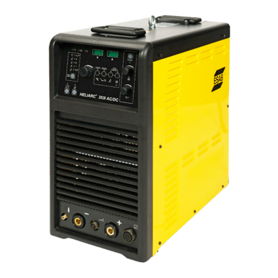
section 2 introDuction introDuction The Heliarc AC/DC 281i, 283i and 353i are state of the art DC and squarewave AC power sources for SMAW (MMA) or GTAW (TIG) welding. They utilize inverter based technology in combination with microprocessor con- trol. The 281i and 283i models are rated 250A / 280A at 100% duty and the more powerful 353i model up to 350A@ 45% duty. - Page 10 section 2 introDuction Heliarc 281i/283i/353i AC/DC For advanced GTAW (TIG) welding Specifications Heliarc 281i AC/DC Heliarc 283i AC/DC Heliarc 353i AC/DC Input voltage 208-240 V 1 ph 50/60 H 460 V 3 ph 50/60 Hz 460 V 3 ph 50/60 Hz Open circut voltage Setting range, TIG AC/DC 4-280 A...
-
Page 11: Installation
1. radio interference ESAB welding power sources have been designed to high standards of electromagnetic compatibility. However, arc welding, by its very nature, generates radio-frequency energy and may cause interference. By installing and using the equipment correctly, in accordance with these instructions, the problems of interference may be minimized. - Page 12 section 3 installation 3. connection to the supply The Heliarc AC/DC 281i requires a single phase 208-240V 60Hz electricity supply fused at 50A for all TIG welding and Stick applications. The 283i and 353i need a standard 3 phase 460V 60Hz electricity supply, note no neutral connection is required. Supplies should be fused at 20A for the 283i and 32A for the 353i, using HRC type fuses.
-
Page 13: Assembly
section 4 assemBlY SECTION 4 ASSEMBLY TROLLEY ASSEMBLY fig. 4-1... - Page 14 section 4 assemBlY SECTION 4 ASSEMBLY TROLLEY ASSEMBLY fig. 4-2...
- Page 15 section 4 assemBlY SECTION 4 ASSEMBLY POWER SOURCE TO TROLLEY ASSEMBLY fig. 4-3...
- Page 16 section 4 assemBlY SECTION 4 ASSEMBLY POWER SOURCE TO TROLLEY ASSEMBLY fig. 4-4 View From “A”...
- Page 17 section 4 assemBlY SECTION 4 ASSEMBLY COOLER ASSEMBLY fig. 4-5 ASSEMBLY SEQUENCE 1_Remove screws M5x12 (8) and door panel (7) 2_Insert the input cable with plug into the trolley. Take it out from the back hole (remove first the plastic cap). Fasten the input cable with screws M5x12 (3) on the back panel (see view "A"). IMPORTANT OPERATION 1_Remove the plastic cap (5) 2_Once the Cooler is instal fasten the safety screw M6x16 (6)
- Page 18 section 4 assemBlY remove upper extension pieces * for 281i & 283i. Warning ensure the green/YelloW earth Wire is correctlY connecteD to the lh terminal. Before energizing the cooler ensure it is correctly filled with coolant, refer to W.C.U. Instruction Sheet, and connect the TIG torch cooling hoses to its front panel.
-
Page 19: Operation
section 5 operation operation controls & operation 1. switching on 1.1 The rear panel mounted rotary switch is the mains power ON/OFF switch. the computer control sYstem memorizes the poWer source Warning control settings at poWer off. if the unit Was in mma moDe at sWitch-off then When the unit is sWitcheD on, ocv Will Be pres- ent at the WelDing output. - Page 20 section 5 operation controls & operation (con't.) 2.3 Momentarily press the Remote Control mode key. The REM. ON LED will light and the L.H. display will flash "REM". Whilst the display is flashing set the minimum/start value of the remote control as required between 4A and 100A using the Main Setting Control and R.H.
- Page 21 section 5 operation SECTION 5 OPERATION CONTROLS & OPERATION (con't.) 5. Selecting Pulse Mode - See Figure 7 Figure 7 - DC & AC Pulsing 5.1 In the standby mode, press the Pulse mode key (F). The associated green ON PULSE LED will illuminate and the digital displays will flash "dut"...
- Page 22 section 5 operation controls & operation (con't.) 7. tig Welding with 2 stroke torch switch (2t) and hf start - see figure 8 Amps Strike Post Purge Time Slope Down Slope Up Time Time t Torch Switch figure 8 - tig 2t operation 7.1 Set the process/mode to TIG 2T and press the HF ON key to select HF start.
- Page 23 section 5 operation CONTROLS & OPERATION (con't.) 8.1 Set the process/mode selector to TIG 4T and press the HF ON key to select HF start. 8.2 Set the desired welding current with the main setting control A. 8.3 Press the SL slope up/down key once to adjust the down slope (DS displayed in V window). Press the SL slope up/down key twice to adjust the up slope (US displayed in V window).
- Page 24 section 5 operation SECTION 5 OPERATION CONTROLS & OPERATION (con't.) 10. GTAW (TIG) Welding with Manually Sequenced Pulsing - See Figure 11 Figure 11 - TIG Lift Arc Mode 10.1 Set the process to TIG mode using the mode selector key. 10.2 Set the desired "peak"...
- Page 25 OPTIMIZING TIG WELDING PERFORMANCE 1. Tungsten Electrode Types ESAB recommends the use of either lanthanated or ceriated tungstens for both AC and DC applications. Either type is suitable for optimum arc striking and stable performance. In the past, for AC TIG applications, pure tungsten would be used. Not the case for these new Heliarc ACDC Square Wave Inverter machines due to the new enhancements in Waveform/Balance control.
- Page 26 section 5 operation SECTION 5 OPERATION OPTIMIZING TIG WELDING PERFORMANCE (con't.) 3. Maximum Current Ratings for Tungsten Electrodes 1/16 3/32" 1/8" 150A 240A 380A AC Balanced 100A 150A 4. AC GTAW (TIG) Welding Using FC-5C Foot Control Unlike other AC TIG equipments the Heliarc AC/DC 281i, 283i and 353i do not use continuous HF to maintain the AC TIG arc.
- Page 27 section 5 operation SECTION 5 OPERATION...
- Page 28 SECTION 5 OPERATION section 5 operation...
- Page 29 SECTION 5 OPERATION section 5 operation 5. Front Control Panel Description and Parameters (con't.)
- Page 30 section 5 operation 5. front panel Description and parameters (con't.) 1. LED Voltage input - The LED is lit when there is presence of input voltage. 2. LED Voltage output - The LED is lit when there is presence of output voltage (in Tig mode only when you press the trigger).
-
Page 31: Additional Features
section 5 operation 5. front panel Description and parameters (con't.) 17. Remote Control Button - This button sets the remote control function. The Display A shows the maximum current. By pressing the button the LED is blinking and adjust the minimum current. The Display V shows MIN and Display A the value from 0-100 Amp. - Page 32 SECTION 5 OPERATION section 5 operation...
- Page 33 SECTION 5 OPERATION section 5 operation...
- Page 34 SECTION 5 OPERATION section 5 operation...
- Page 35 SECTION 5 OPERATION section 5 operation...
- Page 36 SECTION 5 OPERATION section 5 operation...
- Page 37 section 5 operation...
- Page 38 SECTION 5 OPERATION section 5 operation...
- Page 39 section 5 operation...
- Page 40 section 5 SECTION 5 OPERATION operation...
- Page 41 section 5 operation SECTION 5 OPERATION...
- Page 42 section 5 SECTION 5 OPERATION operation...
- Page 43 section 5 operation...
-
Page 44: Section 6 Maintenance
7. Fill up the cooling unit with coolant to the maximum level. 8. Put the cooling unit in position and connect it. 0463 369 001 - 28 - © ESAB AB 2014 Fill up the cooling unit with coolant To fill up the cooling unit with coolant do the following:... -
Page 45: Maintenance
4. Carefully pull out the cooling unit (2), enough to access the coolant tank. 5. Fill up the cooling unit with coolant to the maximum level. 6. Carefully push back the cooling unit and fasten it with the safety bolt (1). - 29 - 0463 369 001 © ESAB AB 2014... - Page 46 MAINTENANCE WARRANTY ESAB offers a full, normally on-site, guarantee on all its welding and cutting equipment. The Heliarc AC/DC 281i, 283i and 353i power sources are guaranteed for a period of 36 months from date of purchase. If during this...
-
Page 47: Warranty
section 7 WarrantY... - Page 48 Welding & cutting products, florence, sc communication guiDe - customer services CUSTOMER SERVICE QUESTIONS: Telephone: (800)362-7080 / Fax: (800) 634-7548 Hours: 8:00 AM to 7:00 PM EST Order Entry Product Availability Pricing Order Information Returns ENGINEERING SERVICE: Telephone: (843) 664-4416 / Fax : (800) 446-5693...
Need help?
Do you have a question about the Heliarc 353iAC/DC and is the answer not in the manual?
Questions and answers