Table of Contents
Advertisement
Quick Links
Advertisement
Table of Contents

Related Manuals for AXIOMTEK OPS883-H Series


Summary of Contents for AXIOMTEK OPS883-H Series
- Page 1 OPS883-H Series Intel Open Pluggable Specification User’s Manual...
-
Page 2: Disclaimers
Axiomtek does not make any commitment to update the information in this manual. Axiomtek reserves the right to change or revise this document and/or product at any time without notice No part of this document may be reproduced, stored in a retrieval system, or transmitted, in any form or by any means, electronic, mechanical, photocopying, recording, or otherwise, without the prior written permission of Axiomtek Co., Ltd. -
Page 3: Safety Approvals
Safety Approvals CE Marking FCC Class A FCC Compliance This equipment has been tested in compliance with the limits for a Class A digital device, pursuant to Part 15 of the FCC Rules. These limits are mean to provide reasonable protection against harmful interference in a residential installation. -
Page 4: Safety Precautions
Safety Precautions Before getting started, please read the following important safety precautions. The OPS883-H series does not come equipped with an operating system. An operating system must be loaded first before installing any software into the computer. Be sure to ground yourself to prevent static charge when installing the internal components. -
Page 5: Table Of Contents
Table of Contents Disclaimers ......................ii Safety Approvals ....................iii Safety Precautions ....................iv CHAPTER 1 INTRODUCTION ................. 1 General Description ................1 System Specifications ................ 2 1.2.1 Main CPU Board ....................2 1.2.2 I/O System ......................2 Mechanical Assembly ................. 4 1.3.1 Dimensions ...................... - Page 6 3.1.6 Audio MIC-IN Connector (SCN2) ..............28 3.1.7 AudioLine-Out Connector (SCN3) ..............28 3.1.8 Battery 2 PIN (BAT1) ..................28 3.1.9 Mini Card Slot (SCN1) ..................29 3.1.10 SSW1 Setting....................30 3.1.11 SATA & SATA Power Connector (SATA1) ..........31 3.1.12 RJ45 (I217LM) (LAN1) ..................
-
Page 7: Chapter 1 Introduction
OPS883-H User’s Manual CHAPTER 1 INTRODUCTION This chapter contains general information and detailed specifications of the OPS883-H series. Chapter 1 includes the following sections: General Description Specification Michanical Assembly Package List General Description Intel Open Pluggable Specification (OPS) Compliance OPS883-H series is based on the 4 generation Intel®... -
Page 8: System Specifications
OPS883-H User’s Manual System Specifications 1.2.1 Main CPU Board LGA1150 socket type 4 generation Intel® Core™ i5/i3/Celeron Processor System Chipset Intel® H81 PCH BIOS American Megatrends Inc. UEFI (Unified Extensible Firmware Interface) BIOS. System Memory ... - Page 9 OPS883-H User’s Manual Dimension (Main Body Size) 200 mm x 119 mm(D) x 30 mm(H) Operation Temperature 0℃ to 45℃ (with airflow 1.2 m/s) NOTE: All specifications and images are subject to change without notice. Introduction...
-
Page 10: Mechanical Assembly
30mm, and it shows the location of the screw holes of front panel as well as the security lock. ※W hile plugging the OPS module, please make sure the heat sink side of OPS module toward the outside. Axiomtek will be out of reasonability if there is any damage occurred due to it. -
Page 11: I/O Outlet
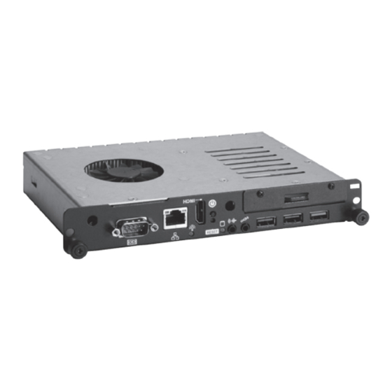
OPS883-H User’s Manual 1.3.2 I/O outlet The following figures show you the locations of the OPS883-H series I/O outlets. 7 8 9 10 Connector Connector JAE TX-25 HDD indicator Antenna opening Audio(Line-out) RS-232 Audio(Mic.-in) Ethernet 2 x USB 2.0 HDMI Output 1 x USB 3.0... -
Page 12: Mechanical Specifications
OPS883-H User’s Manual 1.3.3 Mechanical Specifications OPS883-H series is docked in the reference display panel The OPS883-H Pluggable Module docked at a display panel system. In this reference design, the module is docked and undocked in the vertical direction. NOTE: Please contact Axiomtek for available option display panel. - Page 13 The Guide Rail Mechanism for the OPS883-H series Module You can use the rails alongside of OPS883-H series Module to dock and undock the plug connector at the back of the module to connect with docking board. There are two lock pins on each side of the rail, and they serve as the locking mechanism to attach the lock holes on the series module.
- Page 14 OPS883-H User’s Manual Location of Lock Hole on the Pluggable Module *The drawing is base on Intel Open Pluggable Specification Introduction...
- Page 15 OPS883-H User’s Manual Dimensions of the Guide Rail Introduction...
- Page 16 Vent Holes at the Pluggable Module Back Panel On the OPS883-H series module, it is recommended by Intel that some vent holes be opened at the back so that hot air can escape more easily from the module that the FAR in on both sides of the module back panel should be greater than 0.25.
-
Page 17: Reference Design
Reference Design Display Panel Rear View – Internal The digital signage OPS883-H series prototype is based on a 32” display panel with the functional blocks illustrated. It is mainly a 3 -board partitioning design consisting of the pluggable module, docking board and the panel control board. -
Page 18: Package List
OPS883-H x 1 CD x 1 THERMAL GREASE(Syringe 1G) M2 x 5 screw x 2 M4 x 6 screw x 2 If you cannot find the package or any items are missing, please contact Axiomtek distributors immediately. Introduction... -
Page 19: Chapter 2 Hardware Installation
Pluggable Module Method CPU, Storage, DRAM, Wireless & 3G module Installations The OPS883-H series model offers a convenient drive bay module for users to install CPU, Storage, DRAM, wireless & 3G modules. Please follow the steps: CPU Installation Step 1 Turn off the system, Loosen the screws as illustrated. - Page 20 OPS883-H User’s Manual Step 3 Refer to the following photo to loosen the screws and pillars in advance. NOTE: Please pull out power cable of system fan while installation. Step 4 Then turn over the chassis as per illustrated. NOTE: Please be aware of the CPU FAN Cable, while installing the CPU, you do not need to pull out the cable to avoid cable damage.
- Page 21 OPS883-H User’s Manual Step 5 Remove the CPU waring mylar and then pull out the desktop CPU socket pole. Step 6 Insert the CPU into the slot. Please follow the indication on CPU as mark and slot to ensure the proper insertion of the CPU Step 7 Please make sure CPU has inserted into the socket and the latch is closed.
- Page 22 OPS883-H User’s Manual Step 8 Press pole of the CPU socket firmly, as per illustrated. DRAM Install Step 1 Loosen the screws on the real of chassis as illustrated. Step 2 After losing the screws, extract the real of chassis out of the module. Hardware Installation...
- Page 23 DIMM. 2.5” HDD/ SSD Instllation The OPS883-H series provides one 2.5” SATA HDD tray to install 2.5” HDD. When please refer to the following instructions and illustration. Step 1 Loosen the screws per illustrated.
- Page 24 Step 4 Finally, fasten two screws on HDD cover firmly. Mini PCIe Module Installation The OPS883-H series provides one Mini card slot for user to install mini cards, please refer to the following instructions and illustration. Step 1 Loosen the screws per illustrated.
- Page 25 OPS883-H User’s Manual Step 2 Then open the cover carefully. Step 3 You can find the position of Mini PCIe slot and please insert it then fasten screw of Mini PCIe module by yourself. Hardware Installation...
- Page 26 OPS883-H User’s Manual SIM Card & Antenna Cable Installation Step 1 Install SIM Card module. Place the SIM Card module into the socket and press it firmly down until it is fully located. Step 2 The following photos show you how to connect antenna cable by yourself.
-
Page 27: Pluggble Module Method
Step 1 Pluggable the box into display Caution: When plugging OPS883-H series module into an OPS display, make sure the module’s heat sink is facing outside of the display. Axiomtek is not responsible for any damage caused by wrong installation... - Page 28 OPS883-H User’s Manual This page is intentionally left blank. Hardware Installation...
-
Page 29: Chapter 3 Connectors
OPS883-H User’s Manual CHAPTER 3 CONNECTORS This chapter provides users with detailed description how to set up basic system configuration through the AMIBIOS8 BIOS setup utility. Connectors Connectors connect this board with other parts of the system. Loose or improper connection might cause problems. - Page 30 OPS883-H User’s Manual Board Layout Top side Bottom side Drivers Installation...
-
Page 31: Jae Tx25 Connector (Cn1)
OPS883-H User’s Manual 3.1.1 JAE TX25 Connector (CN1) Connector JAE TX25 CN1 is for JAE interface support. Signal Signal Signal Signal 1 DDP_3N DDP_3P DDP_2N 5 DDP_2P DDP_1N DDP_1P 9 GND 10 DDP_0N 11 DDP_0P 12 GND 13 DDP_AUXN 14 DDP_AUXP 15 DDP_HPD 16 GND 17 TMDS_CLK-... -
Page 32: Cpu Fan (Cn2)
OPS883-H User’s Manual 3.1.2 CPU FAN (CN2) CN2 provides power input and FAN control signal, and you can connect CPU FAN through this connector. Signal FAN CTRL 3.1.3 SIM Card Slot (CN4) This slot supports inserting SIM Card. In order to work properly, the SIM Card must be used together with 3G module. -
Page 33: Hdmi Connector (Cn5)
OPS883-H User’s Manual 3.1.4 HDMI Connector (CN5) The HDMI (High-Definition Multimedia Interface) is a compact digital interface which is capable of transmitting high-definition video and high-resolution audio over a single cable. Signal Signal HDMI OUT_DATA2+ HDMI HDMI OUT_DATA2- OUT_DATA1+ HDMI OUT_DATA1- HDMI OUT_DATA0+... -
Page 34: Audio Mic-In Connector (Scn2)
OPS883-H User’s Manual 3.1.6 Audio MIC-IN Connector (SCN2) Signal MIC_IN_L MIC_IN_R MIC_DETECT 3.1.7 AudioLine-Out Connector (SCN3) Signal LINE_OUT_L LINE_OUT_R LINE_OUT _DETECT 3.1.8 Battery 2 PIN (BAT1) Signal +VBAT Drivers Installation... -
Page 35: Mini Card Slot (Scn1)
OPS883-H User’s Manual 3.1.9 Mini Card Slot (SCN1) This is a PCI-Express Mini Card connector which supports PCI-Express x1 link, USB 2.0 link and 3G wireless network application. Signal Signal Signal WAKE# +3.3VAUX 3 RVD1 RVD2 6 +1.5V CLKREQ# RVD19 9 GND 10 RVD18 11 REFCLK-... -
Page 36: 3.1.10 Ssw1 Setting
OPS883-H User’s Manual 3.1.10 SSW1 Setting ATX/AT Mode Setting/ Clear CMOS/ SLP_S3_Docking (SSW1-Pin8). AT or ATX Select (SSW1- Pin1) Description Settings OFF (Default) Clear CMOS (SSW1- Pin2) Description Settings Clear CMOS OFF (Default) Clear CMOS PCIe Signal Switch (SSW1- Pin3) Description Settings PCIe... -
Page 37: Sata & Sata Power Connector (Sata1)
OPS883-H User’s Manual 3.1.11 SATA & SATA Power Connector (SATA1) Signal Signal +3.3V +3.3V SATA0_TX+ +3.3V SATA0_TX- SATA0_RX- SATA0_RX+ P10 GND P11 GND P12 GND P13 NC P14 NC P15 NC Drivers Installation... -
Page 38: Rj45 (I217Lm) (Lan1)
OPS883-H User’s Manual 3.1.12 RJ45 (I217LM) (LAN1) The RJ-45 connector LAN1 is for Ethernet. To connect the board to 100-Base-T or 1000- Base-T hub, just plug one end of the cable into LAN1 and connect the other end (phone jack) to a 100-Base-T hub or 1000-Base-T hub. -
Page 39: Usb 2.0 Port (Susb2/3)
OPS883-H User’s Manual 3.1.14 USB 2.0 Port (SUSB2/3) Signal USB_POWER USB D0- USB D0+ 3.1.15 COM Port (COM2) The COM Port connector is a standard DB-9 connector. The pin assignment of RS- 232 is listed on the following table Signal DCD, Data carrier detect RXD, Receive data TXD, Transmit data... - Page 40 OPS883-H User’s Manual This page is intentionally left blank. Drivers Installation...
-
Page 41: Chapter 4 Ami Bios Setup Utility
OPS883-H User’s Manual CHAPTER 4 AMI BIOS SETUP UTILITY This chapter provides users with detailed description how to set up basic system configuration through the AMIBIOS8 BIOS setup utility. Starting To enter the setup screens, follow the steps below: Turn on the computer and press the <Del>... -
Page 42: Main Menu
OPS883-H User’s Manual Main Menu When you first enter the Setup Utility, you will enter the Main setup screen. You can always return to the Main setup screen by selecting the Main tab. There are two Main Setup options. They are described in this section. The Main BIOS Setup screen is shown below. ... -
Page 43: Advanced Menu
OPS883-H User’s Manual Advanced Menu The Advanced menu also allows users to set configuration of the CPU and other system devices. You can select any of the items in the left frame of the screen to go to the sub menus: ... - Page 44 OPS883-H User’s Manual ACPI Settings You can use this screen to select options for the ACPI Configuration, and change the value of the selected option. A description of the selected item appears on the right side of the screen. ...
- Page 45 OPS883-H User’s Manual S5 RTC Wake Settings Enable or disable system wake on alarm event. When enabled, System will wake on the hr:min::sec specified AMI BIOS Setup Utility...
- Page 46 OPS883-H User’s Manual Trusted Computing Enables or disables BIOS support for security device. O.S. will not show Security Device. TCG EFI protocol and INT1A interface will not be available. TCG EFI protocol and INT1A interface will not be available. AMI BIOS Setup Utility...
- Page 47 OPS883-H User’s Manual CPU Configuration This screen shows the CPU Configuration, and you can change the value of the selected option. Active Processor Cores To select number of cores is to enable in each processor package. Intel Virtualization Technology Allows a hardware platform to run multiple operating systems separately and simultaneously, enabling one system to virtually function as several systems.
- Page 48 OPS883-H User’s Manual SATA Configuration You can use this screen to select options for the SATA Configuration, and change the value of the selected option. A description of the selected item appears on the right side of the screen. ...
- Page 49 OPS883-H User’s Manual PCH-FW Configuration You can use this screen to confirm ME Firmware version. AMI BIOS Setup Utility...
- Page 50 OPS883-H User’s Manual USB Configuration You can use this screen to select options for the USB Configuration, and change the value of the selected option. A description of the selected item appears on the right side of the screen. ...
- Page 51 OPS883-H User’s Manual F81801 Super IO Configuration Set parameters of Serial Port 1(COM1)/Serial Port 2(COM2) Serial Port Enable or Disable serial port. Device Settings Display the serial port resource. AMI BIOS Setup Utility...
- Page 52 OPS883-H User’s Manual PC Health Status This screen shows the Hardware Health Configuration, and enable or disable smart fan. AMI BIOS Setup Utility...
-
Page 53: Chipset Menu
OPS883-H User’s Manual Chipset Menu The Chipset menu allows users to change the advanced chipset settings. You can select any of the items in the left frame of the screen to go to the sub menus: PCH–IO Configuration System Agent(SA) Configuration AMI BIOS Setup Utility... - Page 54 OPS883-H User’s Manual PCH–IO Configuration PCH Azalia Configuration settings AMI BIOS Setup Utility...
- Page 55 OPS883-H User’s Manual PCH Azalia Configuration Contorl Detection of the Azalia device. Azalia Enable or disable Azalia device. AMI BIOS Setup Utility...
- Page 56 OPS883-H User’s Manual System Agent(SA) Configuration To adjust graphics and memory detail configurations. Graphics Configuration Configure graphics settings. Memory Information Memory configuration parameters AMI BIOS Setup Utility...
- Page 57 OPS883-H User’s Manual Graphics Configuration Select the Video Device which will be activated druing POST. This has no effect if external grpahis present. Primary IGFX Boot Display Select the video device which will be activated du ring POST. It has no effect if external graphics presents VGA modes will be supported only on primary display AMI BIOS Setup Utility...
- Page 58 OPS883-H User’s Manual Memory Information Memory configuration parameters Max TOLUD This item allows you to set Maximum Value of TOLUD AMI BIOS Setup Utility...
-
Page 59: Boot Menu
OPS883-H User’s Manual Boot Menu The Boot menu allows users to change boot options of the system. You can select any of the items in the left frame of the screen to go to the sub menus: Setup Prompt Timeout ... -
Page 60: Security Menu
OPS883-H User’s Manual Security Menu The Security menu allows users to change the security settings for the system. Administrator Password This item indicates whether an administrator password has been set. If the Administrator password is set, BIOS will ask and wait for administrator password entered. -
Page 61: Save & Exit Menu
OPS883-H User’s Manual Save & Exit Menu The Save & Exit menu allows users to load your system configuration with optimal or failsafe default values. Save Changes and Exit When you have completed the system configuration cha nges, select Save Changes and Exit from the Save &... - Page 62 OPS883-H User’s Manual Discard Changes and Reset Select this option to quit Setup without making any permanent changes to the system configuration and reboot the computer. Select Discard Changes and Reset from the Save & Exit menu and press <Enter>. Select Yes to discard changes and reset.
-
Page 63: Appendix Areference Documents
OPS883-H User’s Manual APPENDIX A REFERENCE DOCUMENTS Reference Documents... - Page 64 OPS883-H User’s Manual This page is intentionally left blank. Reference Documents...
-
Page 65: Appendix Bwatchdog Timer
OPS883-H User’s Manual APPENDIX B WATCHDOG TIMER Watchdog Timer Setting After the system stops working for a while, it can be auto -reset by the W atchdog Timer. The integrated Watchdog Timer can be set up in the system reset mode by program. - Page 66 OPS883-H User’s Manual This page is intentionally left blank. Watchdog Timer...
Need help?
Do you have a question about the OPS883-H Series and is the answer not in the manual?
Questions and answers