Table of Contents
Advertisement
Quick Links
Advertisement
Table of Contents

Related Manuals for AXIOMTEK GOT321B-ADL-WCD


Summary of Contents for AXIOMTEK GOT321B-ADL-WCD
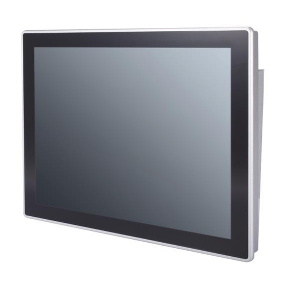
- Page 1 GOT321B-ADL-WCD All-in-One 21.5” FHD TFT Fanless Touch Panel PC User’s Manual...
-
Page 2: Disclaimers
Axiomtek does not make any commitment to update the information in this manual. Axiomtek reserves the right to change or revise this document and/or product at any time without notice. No part of this document may be reproduced, stored in a retrieval system, or transmitted, in any form or by any means, electronic, mechanical, photocopying, recording, among others, without prior written permission from Axiomtek Co., Ltd. -
Page 3: Safety Precautions
Most electronic components are sensitive to static electrical charge. Disconnect the power cord from the GOT321B-ADL-WCD prior to any installation. Be sure both the system and the external devices are turned off. Sudden surge of power could ruin sensitive components. Make sure the GOT321B-ADL-WCD is properly grounded. -
Page 4: Table Of Contents
Table of Contents Disclaimers ..................... ii Safety Precautions ..................iii Section 1 Introduction ..........1 General Description ................1 Specifications ..................2 Dimensions and Outlines ..............4 I/O Outlets .................... 6 Packing List ..................8 Section 2 Hardware and Installation ...... 9 Jumper Settings .................. - Page 5 USB Configuration 3.5 Chipset Menu ............36 Boot Menu ..................40 Security Menu ..................41 Save & Exit Menu ................42 Section 4 Drivers Installation ......43 Operating System ................43 4.1.1 Driver download................... 43 Touch Screen ..................44 Appendix A TPM BitLocker Settings .......
- Page 6 This page is intentionally left blank.
-
Page 7: Introduction
⚫ Package List General Description The GOT321B-ADL-WCD adopts a 21.5-inch FHD TFT LCD with 400-nits brightness, a high performance LGA1700 socket for 13/12 generation Intel® Core™ i7/i5/i3 & Pentium® processor (Tj 100°C) up to 35W,, and an Intel® H610 Express chipset to provide excellent computing performance. -
Page 8: Specifications
⚫ Designed for extended operating temperature range and ingress protection The GOT321B-ADL-WCD’s compact industrial design and fanless cooling system allow the panel PC to sustain an extended operating temperature range between -10°C and +50°C, making the system a power-efficient solution. It also features an IP65 front bezel for protection from liquid and dust. - Page 9 GOT321B-ADL-WCD User’s Manual ⚫ Storage 1 x 2.5” SATA HDD(WT)/SSD (7mm and 9.5mm height, removable) ◼ ⚫ Power connector ◼ 1 x Phoenix type connector for DC power input Mechanical/Environmental Specifications ⚫ 21.5” FHD (1920 x 1080) LCD 400 nits with LED backlight ⚫...
-
Page 10: Dimensions And Outlines
GOT321B-ADL-WCD User’s Manual Dimensions and Outlines Below shows the outlines and dimensions of GOT321B-ADL-WCD. Dimension: 542 mm (21.34") (W) x 76.4 mm (3.01") (D) x 338 mm (13.31") (H) Cut out dimension of GOT321B-ADL-WCD: 397 x 253 mm Introduction... - Page 11 GOT321B-ADL-WCD User’s Manual Back outline of the GOT321B-ADL-WCD NOTE The limited od wall depth is 6mm in panel mount. Introduction...
-
Page 12: I/O Outlets
Figure 1-2,1-3 and Table 1-1,1-2 illustrate I/O locations and their functions of the GOT321B-ADL-WCD. Figure 1-2 Side View of the GOT321B-ADL-WCD Table 1-1 Functions of the Side panel of the GOT321B-ADL-WCD Function 1 x Display monitor ON/OFF 1 x Brightness up... - Page 13 GOT321B-ADL-WCD User’s Manual Figure 1-3 Side View of the GOT321B-ADL-WCD Table 1-2 Functions of the I/O Outlets of the GOT321B-ADL-WCD Function Power Button Phoenix type connector(Support IGN) Grounding hole Remote power switch USB 3.2 Gen1 USB 2.0 COM1 RS-232/422/485 HDMI...
-
Page 14: Packing List
GOT321B-ADL-WCD User’s Manual Packing List The package bundled with the GOT321B-ADL-WCD should contain the following items: ⚫ GOT321B-ADL-WCD x 1 ⚫ Panel mount kit set x1 ⚫ Wall mount (optional) ⚫ Phoenix terminal x 1 If any above-mentioned item is missing, please contact an Axiomtek distributor immediately. -
Page 15: Hardware And Installation
Section 2 Hardware and Installation The GOT321B-ADL-WCD provides rich I/O ports and flexible expansion features for users to perform various tasks. This section provides detailed information on the hardware components of the panel PC as well as installation instructions, including the following subsections: ⚫... -
Page 16: Com1 Data/Power Select (Jp1)
GOT321B-ADL-WCD User’s Manual 2.1.1 COM1 Data/Power Select (JP1) The COM1 port has +5V power capability on DCD and +12V on RI by setting JP1. Function Setting Power: Set COM1 pin 1 to +5V 1-3 close Data: Set COM1 pin 1 to DCD (Default) -
Page 17: Connectors
GOT321B-ADL-WCD User’s Manual Connectors Signals go to other parts of the system through connectors. Loose or improper connection might cause problems, please make sure all connectors are properly and firmly connected. Here is a summary table showing connectors on the hardware. -
Page 18: Com D-Sub Connector (Cn1, Cn17)
GOT321B-ADL-WCD User’s Manual 2.2.1 COM D-Sub Connector (CN1, CN17) The CN1, CN17 is 9-pin D-Sub connector for COM1, COM2 serial port interfaces on the rear I/O. The COM1 supports RS-232/422/485 mode and the COM2 support only RS-232. The pin assignments of RS-232/422/485 are listed in table below. -
Page 19: Ethernet Ports (Lan1 And Lan2)
GOT321B-ADL-WCD User’s Manual 2.2.4 Ethernet Ports (LAN1 and LAN2) The motherboard supports two Ethernet ports (CN9, CN12): two RJ45 connectors with LAN1: Intel® i219-V controller support 10/100/1000 Mbps. LAN2: Intel® i225-V controller support 10/100/1000/2500Mbps. LAN2 Signal LAN1 Signal Tx+ (Data transmission positive) -
Page 20: Pci-Express Mini Card Connector (Cn21)
GOT321B-ADL-WCD User’s Manual 2.2.5 PCI-Express Mini Card Connector (CN21) The CN21 complies with PCI-Express Mini Card Spec. V1.2. Signal Signal WAKE# +3.3VAUX +1.5V CLKREQ# UIM_PWR/NC UIM_DAT/NC REFCLK- UIM_CLK/NC REFCLK+ UIM_REST/NC UIM_VPP/NC PERST# PCIE_RX_D- +3.3VAUX PCIE_RX_D+ +1.5V SMB_CLK PCIE_TX_D- SMB_DATA PCIE_TX_D+... -
Page 21: Key E Socket (Cn22)
GOT321B-ADL-WCD User’s Manual 2.2.6 M.2 Key E Socket (CN22) The motherboard comes with one M.2 Key E socket (PCIe & USB2.0), The CN22 supports CNVi module. Signal Signal +3.3V_SBY USB_D+ +3.3V_SBY USB_D- M.2_BT_PCMCLK CNVI_WGR_DATA1_D- M.2_BT_PCMRST CNVI_WGR_DATA1_D+ M.2_BT_PCMIN M.2_BT_PCMOUT CNVI_WGR_DATA0_D- CNVI_WGR_DATA0_D+... -
Page 22: Hdmi1.4 Connector (Cn6)
GOT321B-ADL-WCD User’s Manual 2.2.7 HDMI1.4 Connector (CN6) The HDMI (High-Definition Multimedia Interface) is a compact digital interface which can transmit high-definition video and high-resolution audio over a single cable. Signal Signal HDMI OUT_DATA2+ HDMI OUT_DATA2- HDMI OUT_DATA1+ HDMI OUT_DATA1- HDMI OUT_DATA0+... -
Page 23: Sim Card Slot (Cn25)
GOT321B-ADL-WCD User’s Manual 2.2.9 SIM Card Slot (CN25) The CN25 is for inserting SIM Card which is mainly used in wireless network application. Signal UIM_PWR UIM_RST UIM_CLK DATA 2.2.10 Remote Power Switch Connector (PWRBT1) One 2-pin connector output for remote power on/off switch. -
Page 24: Mounting Methods
WARNING the installation. There are four ways to install the GOT321B-ADL-WCD, namely: panel/ VESA/ wall/ desktop mount. The GOT321B-ADL-WCD is designed for panel mount application. To mount the GOT321B-ADL-WCD, the standard set of mounting kit (10pcs included in the system packaging) is needed. - Page 25 GOT321B-ADL-WCD User’s Manual Alternatively, the GOT321B-ADL-WCD can be installed by way of VESA mount which is in the dimensions of 100x100 mm. Simply fix four screws to fasten the kit from the back chassis, as shown in Diagram 2-2. Additionally, users can otherwise go for wall mount as an option, as shown in Diagram 2-3.
-
Page 26: Hardware Installation
GOT321B-ADL-WCD User’s Manual Hardware Installation 2.4.1 Installing an SSD The GOT321B-ADL-WCD provides a convenient SSD bracket for users to install 1 x 2.5” SATA SSD. Please follow the steps: Step 1 Unfastening the screw to slide open. Insert the 2.5” SSD into the bracket and fasten the four screws on the bottom Step 2 side of the bracket to hold the HDD firmly to the bracket. - Page 27 GOT321B-ADL-WCD User’s Manual Step 2 Install the SO-DIMM module into the slot (see red frame line) and press it firmly down until it seats correctly. Step 3 In the red box in the left picture, place the Thermal Pad on the iron block.
-
Page 28: Wireless Lan Module Installation (Optional)
GOT321B-ADL-WCD User’s Manual 2.4.3 Wireless LAN Module Installation (optional) The GOT321B-ADL-WCD provides optional wireless LAN module to install. When installing the wireless LAN module, refer to the following instructions and illustration: Step 1 Open the back cover and locate PCIe Mini-Card slot. -
Page 29: Power Input
GOT321B-ADL-WCD User’s Manual Power Input The GOT321B-ADL-WCD is equipped with a Phoenix type power connector which supports 12V/19V/24VDC in. Please follow the signs on the power connector to connect to DC power source (see Figure 2-2). Figure 2-2: Power connector... -
Page 30: Ami Bios Setup Utility
GOT321B-ADL-WCD User’s Manual Section 3 AMI BIOS Setup Utility The AMI UEFI BIOS provides users with a built-in setup program to modify basic system configuration. All configured parameters are stored in a flash chip to save the setup information whenever the power is turned off. This Section provides users with detailed description about how to set up basic system configuration through the AMI BIOS setup utility. - Page 31 GOT321B-ADL-WCD User’s Manual Hot Keys Description → Left/Right The Left and Right <Arrow> keys allow you to select a setup screen. The Up and Down <Arrow> keys allow you to select a setup screen or sub Up/Down screen. The <Enter> key allows you to display or change the setup option listed for a Enter particular setup item.
-
Page 32: Main Menu
GOT321B-ADL-WCD User’s Manual Main Menu When you first enter the setup utility, you will enter the Main setup screen. You can always return to the Main setup screen by selecting the Main tab. System Time/Date can be set up as described below. -
Page 33: Advanced Menu
GOT321B-ADL-WCD User’s Manual Advanced Menu The Advanced menu also allows users to set configuration of the CPU and other system devices. You can select any of the items in the left frame of the screen to go to the sub menus: ►... - Page 34 GOT321B-ADL-WCD User’s Manual ⚫ CPU Configuration This screen shows CPU information. Intel (VMX) Virtualization Technology Enable or disable Intel Virtualization Technology. When enabled, a VMM (Virtual Machine Mode) can utilize the additional hardware capabilities. It allows a platform to run multiple operating systems and applications independently, hence enabling a single computer system to work as several virtual systems.
- Page 35 GOT321B-ADL-WCD User’s Manual ⚫ Trusted Computing This screen provides function for specifying the TPM setting. TPM Device Selection select PTT: Intel® build-in TPM dTPM: External extended TPM Security Device Support Enable or disable BIOS support for security device. OS will not show security device...
- Page 36 GOT321B-ADL-WCD User’s Manual ⚫ ACPI Settings ACPI Sleep State When the suspend button is pressed, the ACPI (Advanced Configuration and Power Interface) sleep state is S3 (Suspend to RAM). S3 Video Repost On enabling, Video Option ROM will be dispatched during S3 resume.
- Page 37 GOT321B-ADL-WCD User’s Manual ⚫ F81966 Super IO Configuration You can use this screen to select options for the Super IO Configuration and change the value of the selected option. A description of the selected item appears on the right side of the screen.
- Page 38 GOT321B-ADL-WCD User’s Manual ⚫ Serial Port 1 Configuration Serial Port Enable or disable serial port 1. Change Settings Select an optimal setting for Super IO device. Auto IO=3F8h, IRQ=4; IO=3F8h, IRQ=3, 4, 5, 6, 7, 9, 10, 11, 12; IO=2F8h, IRQ=3, 4, 5, 6, 7, 9, 10, 11, 12;...
- Page 39 GOT321B-ADL-WCD User’s Manual ⚫ Serial Port 2~4 Configuration Serial Port Enable or disable serial port 2~4. Change Settings Select an optimal setting for Super IO device. For serial port 2: Auto IO=2F8h, IRQ=3; IO=3F8h, IRQ=3, 4, 5, 6, 7, 9, 10, 11, 12;...
- Page 40 GOT321B-ADL-WCD User’s Manual ⚫ Hardware Monitor This screen monitors hardware health status. This screen displays the temperature of system and CPU, cooling fans speed in RPM and system voltages (VCCIO, CPU SA, +5V and +12V). ⚫ Serial Port 1 Configuration Select RS-232/422/485 mode for serial port 1.
- Page 41 GOT321B-ADL-WCD User’s Manual ⚫ USB Configuration USB Devices Display all detected USB devices Drivers Installation...
-
Page 42: Usb Configuration 3.5 Chipset Menu
GOT321B-ADL-WCD User’s Manual ⚫ Network Stack Configuration Network Stack Enable or disable UEFI Network Stack. IPv4/IPv6 PXE Support Enable or disable IPv4 PXE boot support. If disabled, IPv4/IPv6 PXE boot support will not be available. IPv4/IPv6 HTTP Support Enable or disable IPv4/IPv6 HTTP boot support. If disabled, IPv4/IPv6 HTTP boot support will not be available. - Page 43 The Chipset menu allows users to change the advanced chipset settings. You can select any of the items in the left frame of the screen to go to the sub menus: ► System Agent (SA) Configuration If there are any relevant settings that need to be changed, please contact Axiomtek. ► PCH-IO Configuration ►...
- Page 44 GOT321B-ADL-WCD User’s Manual ⚫ PCH-IO Configuration This screen allows you to set PCH parameters. HD Audio Control detection of the HD Audio device. Disabled: HDA will be unconditionally disabled. Enabled: HDA will be unconditionally enabled. Auto: HDA will be enabled if present, disabled otherwise.
- Page 45 GOT321B-ADL-WCD User’s Manual ⚫ Onboard Device Onboard LAN 1/2 Enable or disable onboard LAN 1/2. Drivers Installation...
-
Page 46: Boot Menu
GOT321B-ADL-WCD User’s Manual Boot Menu The Boot menu allows users to change boot options of the system. Setup Prompt Timeout Number of seconds to wait for setup activation key. 65535(0xFFFF) means indefinite waiting. Bootup NumLock State Select the keyboard Numlock state. -
Page 47: Security Menu
GOT321B-ADL-WCD User’s Manual Security Menu The Security menu allows users to change the security settings for the system. Administrator Password Set administrator password. User Password Set user password. Drivers Installation... -
Page 48: Save & Exit Menu
GOT321B-ADL-WCD User’s Manual Save & Exit Menu The Save & Exit menu allows users to load your system configuration with optimal or fail-safe default values. ⚫ Discard Changes and Exit Exit system setup without saving any changes. ⚫ Save Changes and Reset Reset the system after saving the changes. -
Page 49: Drivers Installation
Section 4 Drivers Installation Operating System GOT321B-ADL-WCD is compatible with operating systems Windows 11 and Windows 11 IoT Enterprise. To facilitate the installation of system drivers, please carefully read the instructions in this section before any of such installation. 4.1.1 Driver download Please download the GOT321B-ADL-WCD driver from Axiomtek’s official website... -
Page 50: Touch Screen
GOT321B-ADL-WCD User’s Manual Touch Screen The GOT321B-ADL-WCD adopts projected capacitive multi-touch screen of which specifications are listed below. Users should install the touch driver for calibration to allow the user to operate the touch panel using multi-finger touch functions on the Windows 11 and Windows11 IoT Enterprise environments. -
Page 51: Appendix Atpm Bitlocker Settings
GOT321B-ADL-WCD User’s Manual Appendix A TPM BitLocker Settings 1. Setup BitLocker Drive Encryption main storage. Press <Win + R> and type “Control Panel”, then select BitLocker Drive Encryption. TPM BitLocker Settings... - Page 52 GOT321B-ADL-WCD User’s Manual 2. Insert an external storage device, for example USB Storage. Back up BitLocker recovery key in a new file and save it to the USB Storage. TPM BitLocker Settings...
- Page 53 GOT321B-ADL-WCD User’s Manual 3. Please follow the steps below to encrypt your storage device: TPM BitLocker Settings...
- Page 54 GOT321B-ADL-WCD User’s Manual Now, the system prompts that the operating system drive encryption is in progress, and the encryption progress is checked. TPM BitLocker Settings...
- Page 55 GOT321B-ADL-WCD User’s Manual Select and click the icon in the lower right corner to complete the encryption. TPM BitLocker Settings...
- Page 56 GOT321B-ADL-WCD User’s Manual 4. Confirm the completion of encryption. TPM BitLocker Settings...
- Page 57 GOT321B-ADL-WCD User’s Manual 5. Disable TPM function in BIOS Setup Utility. 6. When the system is powered on and you see the following screen, it means the TPM module function is working fine. Note that BitLocker cannot be executed if your system does not have TPM function.
- Page 58 GOT321B-ADL-WCD User’s Manual NOTE: System with no TPM function support is as below: TPM information is not found in Device Manager. When trying to turn on Bitlocker, the following error message shows up. TPM BitLocker Settings...
Need help?
Do you have a question about the GOT321B-ADL-WCD and is the answer not in the manual?
Questions and answers