Table of Contents
Advertisement
Advertisement
Table of Contents

Subscribe to Our Youtube Channel
Related Manuals for DeDietrich GT 530-7


Summary of Contents for DeDietrich GT 530-7
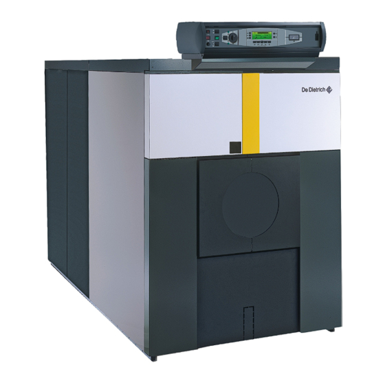
- Page 1 Fuel oil/gas boilers GT 530 Installation and Service Manual 300011906-001-D...
- Page 2 Declaration of conformity CE The appliance complies with the standard model described in declaration of compliance . It is manufactured and distributed pursuant to the requirements of european directives. The original of the declaration of compliance is available from the manufacturer.
-
Page 3: Table Of Contents
Contents Introduction ................5 Symbols and abbreviations . - Page 4 Commissioning ............... . .23 Symbols and abbreviations .
-
Page 5: Introduction
1 Introduction 1.1 Symbols and abbreviations Caution danger Reference Risk of injury and damage to equipment.Attention must be Refer to another manual or other pages in this instruction paid to the warnings on safety of persons and equipment. manual. Specific information DHW: Domestic hot water Information must be kept in mind to maintain comfort. -
Page 6: Homologations
1.3 Homologations 1.3.1 Certifications Certificate of compliance (For France) CE identification no: 1312 AQ 954 (France). In application of Article 25 of the Order of 27 April 2009 amending the CE identification no: 1312 AQ 953 (Germany, Switzerland). Order of 2 August 1977 amended and Article 1 of the amended Order of 05/02/1999, the installer is required to draw up certificates of conformity approved by the Ministers responsible for construction and gas safety:... -
Page 7: Safety Instructions And Recommendations
2 Safety instructions and recommendations 2.1 Safety instructions For a proper operating of the boiler, follow carefully the Before any work, switch off the mains supply to the instructions. appliance. Only qualified professionals are authorised to work on the Keep to the polarity shown on the terminals: phase (L), appliance and the installation. -
Page 8: Technical Description
3 Technical description 3.1 General description The boilers of the GT 530 range are pressurised hot water boilers designed for connecting to a flue pipe which require a separate automatic fuel-oil or gas burner. 3.2 Composition of the range 3.2.1 Standard control panel- S3 Standard panel to be fitted The standard panel is used to connect the boiler to the boiler room... -
Page 9: Diematic-M3 Control Panel
3.2.3 DIEMATIC-m3 control panel Separate panel Side panel Top of the range electronic control panel with digital display, A version of the DIEMATIC-m3 control panel with lateral comprising the settings, control and safety devices allowing the boiler attachment is also available. to operate autonomously. -
Page 10: Technical Specifications
3.3 Technical specifications 3.3.1 Boilers for following countries: France, Algeria, Belgium, Bulgaria, China, Cyprus, Spain, Greece, Luxemburg, Poland, Portugal, Czech Republic, Romania, Tunisia Conditions of use: Maximum operating pressure: 6 bar Maximum operating temperature: 100 °C Boiler thermostat setting: 30 to 90°C Safety thermostat setting: 110 °C Boiler -522... -
Page 11: Boilers For Following Countries: Germany, Austria, Serbia, Slovenia
3.3.2 Boilers for following countries: Germany, Austria, Serbia, Slovenia Conditions of use: (in accordance with TRD 702) Boiler thermostat setting: 30 to 90°C Maximum operating pressure: 6 bar Safety thermostat setting: 110 °C Maximum operating temperature: 100 °C Maximum operating temperature: 120 °C Boiler -522 -525... -
Page 12: Boilers For Following Countries: Switzerland
3.3.3 Boilers for following countries: Switzerland Conditions of use: Maximum operating pressure: 6 bar Maximum operating temperature: 100 °C Boiler thermostat setting: 30 to 90°C Safety thermostat setting: 110 °C Boiler -522 -525 Useful output 1000 Power input 1030 1075 Number of sections Water content 1019... -
Page 13: Boilers For Following Countries: Russia
3.3.4 Boilers for following countries: Russia Conditions of use: (in accordance with TRD 702) Boiler thermostat setting: 30 to 90°C Maximum operating pressure: 6 bar Safety thermostat setting: 110 °C Maximum operating temperature: 100 °C Maximum operating temperature: 120 °C Boiler -522 -525... -
Page 14: Installation
4 Installation 4.1 Regulations governing installation 4.1.1 In general Installation must be carried out in accordance with the prevailing regulations, the codes of practice and the recommendations in these instructions. 4.1.2 In particular for France Establishments open to the public Heating installations must be designed and constructed in such a way as to prevent the return of water from the heating circuit and Statutory terms and conditions of installation:... -
Page 15: In Particular For Germany
4.1.3 In particular for Germany Abide by the following standards, rules and directives when installing - DIN 4753: drinking and industrial water heating installations and commissioning the boiler: - DIN 1988: technical rules on drinking water installations (TRW) - DVGW-TRGI: technical rules on gas installations, including - DIN 4705: calculation of chimney dimensions complementary equipment - DIN EN 12828 (June 2003 edition): heating systems in buildings. -
Page 16: Data Plate
Boiler -522 -525 A (mm) B3, K3, 1761 1872 1983 2094 2205 2316 2427 2538 2649 2760 2871 3017 3128 3279 3390 3501 3612 3723 3834 DIEMATIC-m3 Standard 1606 1717 1828 1939 2050 2161 2272 2383 2494 2605 2716 2862 2973 3124 3235... -
Page 17: Boiler Location
4.3.3 Boiler location For the assembly and because of their design, GT 530 boilers require If the boiler location is not determined precisely, leave enough space no special base. Their closed furnace system means that the floor around the boiler to facilitate monitoring and maintenance need not have refractory properties. -
Page 18: Ventilation
4.3.4 Ventilation The location of air inlets in relation to the high ventilation openings In order to avoid damage to the boiler, it is necessary to shall ensure that the air is renewed in the entire volume of the boiler prevent the contamination of combustion air by chlorine room. -
Page 19: Hydraulic Connections
4.4 Hydraulic connections 4.4.1 Dimensional information required Draining outlet 3/4" Heating return: - 7 to 17 sections: 139.7 - 5" - 18 to 25 sections: 159 - 6" weld. Heating flow: - 7 to 17 sections: 139.7 - 5" - 18 to 25 sections: 159 - 6" weld. -
Page 20: Hydraulic Connection Of The Heating Circuit
4.4.3 Hydraulic connection of the heating circuit Water flow in the boiler Operation with 2-stage burner The water flow in the boiler when the burner is operating must - The water temperature in the boiler is maintained at 50°C or more; correspond with the following formulae: The first stage must be set to a minimum of 30% of the nominal stage. -
Page 21: Filling The System
4.5 Filling the system Filling shall be performed with a low flow rate from a low point in the VERY IMPORTANT: Instructions for starting up the boiler boiler room in order to ensure that all the air in the boiler is bled from for the first time after the system is fully or partly drained: the high point of the system. -
Page 22: Chimney Connection
4.7 Chimney connection The high-performance features of modern boilers and their use in For this reason: specific conditions as a result of the advance in burner technology - Use flue gas pipes designed to enable the flow of condensates (e.g. first-stage or low modulation range operation) lead to very low which may result from such operating modes in order to prevent flue gas temperatures (<160°C). -
Page 23: Fuel-Oil Or Gas Connections
4.8 Fuel-oil or gas connections Refer to the instructions supplied with the burner. 4.9 Electrical connections Refer to the connection instructions supplied with the control panel.. 5 Commissioning See: - Control panel instructions - Burner instructions - Domestic hot water calorifier instructions 6 Switching off the boiler DIEMATIC-m3 control panel Set the On/Off switch to O. -
Page 24: Checking And Maintenance
7 Checking and maintenance 7.1 System maintenance 7.1.1 Water level Regularly check the level of water in the system and top up if This operation should be required only a few times in each heating required, taking care that cold water is not added suddenly into the season, with very low quantities of water;... - Page 25 Step 4: Step 3: Remove the left and right-hand casing covers. Remove the baffle plates from the upper flue ways. Remove the top insulating material. Carefully sweep the flue ways with the brush supplied for that purpose. Brush the baffle plates as well. If possible, use a vacuum cleaner.
- Page 26 Step 7: Step 8: Unscrew the 8 closing nuts and open the furnace door. Brush out the inside of the furnace. Clean the soot accumulated in the furnace and lower flue ways with These 3 screws must not be unfastened in any event. a vacuum cleaner.
-
Page 27: Chemical Sweeping
7.2.2 Chemical sweeping General principle - Direct application to the heating surfaces with aerosol sprays. - The concentrates are diluted in the proportions 1/5 to 1/20 Boilers are traidtionally swept mechanically. There are now chemical ((depending on the product and the condition of the boiler). sweeping methods which facilitate this maintenance work. -
Page 28: Maintenance Of The Burner
Cleaning - Remove the baffle plates. - Light sweeping will remove the pulverent residues remaining after combustion. - The remaining pulverent residues are easy to remove by sweeping or vacuum cleaning. For certain products, brief application after cleaning has a preventive effect, limiting deposits on the heating surfaces. -
Page 29: Spare Parts - Gt 530
8 Spare parts - GT 530 To order a spare part, quote the reference number next to the part required 300011906-002-B Boiler body + Miscellaneous DE DIETRICH THERMIQUE S.A.S. - Spare parts centre 4 rue d’Oberbronn - F-67110 REICHSHOFFEN - +33 (0)3 88 80 26 50 - +33 (0)3 88 80 26 98 dedietrichthermique.com... - Page 30 Insulation GT 530 25/01/2012 - 300011906-001-D...
- Page 31 Casing 25/01/2012 - 300011906-001-D GT 530...
-
Page 32: Control Panels
Control panels Refer to the Spare Parts list in the panel instructions. S3 control panel - Package MD4 K3 control panel Package MD2 Side panel - Package MD139 Separate panel - DIEMATIC-m3 control panel Package MD1 Side panel - Package MD138 Separate panel - B3 control panel Package MD3... - Page 33 Ref. Code no. Description Ref. Code no. Description 8015-8920 Assembly rod Ø 14 - 2398 mm 20 sections Boiler body + Accessories 8015-8921 Assembly rod Ø 14 - 2511 mm 21 sections Base frame 8015-8922 Assembly rod Ø 14 - 2623 mm 22 sections 8259-8953 Complete frame 7 sections 8015-8923...
- Page 34 Ref. Code no. Description Ref. Code no. Description 9757-0426 Furnace door Ø 186 Insulating material for body 9757-0427 Furnace door Ø 210 8555-5516 Complete insulating material for body 7 sections 9757-0428 Furnace door Ø 295 8555-5517 Complete insulating material for body 8 and 9 sections 9757-0429 Furnace plate Ø...
- Page 35 Ref. Code no. Description Ref. Code no. Description 8555-8017 rail 2275 mm 8259-8021 Lower left-hand rear panel 8555-8018 rail 2365 mm 8259-8022 Lower right-hand rear panel 8555-8021 supplementary rail 1246 mm 8259-0518 Panel for furnace door 8555-8035 left-hand cable channel 1260 mm 8555-8519 Control panel trim 8555-8036...
-
Page 36: Warranty Terms
Warranty You have just purchased one of our appliances and we thank you Italy for the trust you have placed in our products. Please note that your The duration of our warranty is shown on the certificate delivered appliance will provide good service for a longer period of time if it is with the appliance. - Page 37 25/01/2012 - 300011906-001-D GT 530...
- Page 38 GT 530 25/01/2012 - 300011906-001-D...
- Page 39 25/01/2012 - 300011906-001-D GT 530...
- Page 40 DE DIETRICH THERMIQUE S.A.S +7 (495) 221-31-51 DUEDI S.r.l. DE DIETRICH THERMIQUE Iberia S.L.U. www.duediclima.it www.dedietrich-calefaccion.es Distributore Ufficiale Esclusivo Av. Princep d’Astúries 43-45 De Dietrich-Thermique Italia 08012 BARCELONA Via Passatore, 12 - 12010 +34 932 920 520 San Defendente di Cervasca...
Need help?
Do you have a question about the GT 530-7 and is the answer not in the manual?
Questions and answers