Table of Contents
Advertisement
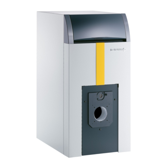
GT 220 A
Oil-Gas Fired Hot Water boiler
Installation and operating instructions
Warning:
Before putting the boiler into operation read this manual
carefully.
Warning:
The operating manual is part of the documentation that is
delivered to the installation's operator. Go through the
information in this manual with the owner/operator and
make sure that he or she is familiar with all the necessary
operating instructions.
82274096
Notice:
This manual must be retained for future reference. Improper
installation, adjustment, alteration, service or maintenance can
cause injury, loss of life or property damage. For assistance or
additional information consult a qualified installer, service agency
or the gas supplier.
English
11/20/09
11-20-09
Advertisement
Table of Contents

Subscribe to Our Youtube Channel
Related Manuals for DeDietrich GT 220 A


Summary of Contents for DeDietrich GT 220 A
-
Page 1: Installation And Operating Instructions
GT 220 A English Oil-Gas Fired Hot Water boiler 11/20/09 Installation and operating instructions Warning: Notice: This manual must be retained for future reference. Improper Before putting the boiler into operation read this manual installation, adjustment, alteration, service or maintenance can carefully. - Page 2 Guideline of Notices Safety Considerations Warning: Please observe the following safety instructions. indicates presence of hazards that can cause, if not Read this manual carefully. avoided, severe personal injury, death or substantial Correct in stallation and adjustment of the burner and the control property damage.
-
Page 3: Table Of Contents
Contents Regulations and guidelines ..............4 General . -
Page 4: Regulations And Guidelines
Regulations and guidelines The installation must conform to the requirements of the authority Only a qualified installing contractor may carry out the installation, the having jurisdiction or, in th e absence of such re quirements, to the initial st art-up, the connection for fixed gas and vent gas, and National Fuel Gas Code, ANSI Z 223.1 / NFPA 54. - Page 5 GT 220A Series - Cast Iron Series Technical Specification Data Table Model Item Unit GT 224A GT 225A GT 226A GT 227A GT 228A Firing Sequence Consult Burner Technical Data [CSA] - Gas Input 50.7 65.5 80.3 95.1 105.7 1.20 1.55 1.90 2.25...
-
Page 6: Main Dimensions
3 Main Dimensions (less applied burner) B Ø flue gas nozzle heating outlet D Ø 13 /16 heating return D Ø Model B = ø GT 224A 23 5/16 in. 16 11/16 in. 1¼ in. GT 225A 28 5/16 in. 21 11/16 in. -
Page 7: Installation
Installation 1 Installing the boiler The boiler does not require any special housekeeping pad as it has been provided with a study frame and leveling bolts for the final installation, but a non combustible pad is suggested to keep occasional water away from the boiler. The boiler requires clearance for combustibles and for servicing, the recommended clearance as shown in the table below. -
Page 8: Levelling
Combustion Air Supply Please note that boilers installed in or close to rooms in The location of air inlets in relation to the high ventilation openings shall ensure that the air is renewed in the entire volume of the boiler which the atmosphere is polluted with chlorine or fluorine room. -
Page 9: Chimney Connection
Chimney connection 1 Venting the boiler The boiler must be connected to a venting system that will safely and effectively discharge all flue gases to the outside in an effective manner. Do not Co-Vent a Direct Vent or Sidewall vent system boiler, these venting options are specifically designed for single boiler venting, follow all local and national codes. - Page 10 Venting 3. Boiler Venting & Chimney General Caution & Warning: It is advised and recommended that the heating contractor-professional apply vent materials that are approved and agency listed. Installation of any venting must follow all local codes in conjunction with vent manufacturer instructions and appliance manufacturer instructions.
- Page 11 Venting 3.1 Boiler Venting – Category I & II Typical Layouts and Requirements. Caution & Warning: Improperly sealed venting system could result in carbon monoxide [CO] poisoning; ensure adequate support and fastening of the system. Ensure venting can safely exhaust all flue gases outside in an effective manner. These systems must operate under a negative vent pressure condition that is stable.
- Page 12 3.2 Boiler Venting – Category III & IV Vent Systems Typical Layouts and Requirements. Caution & Warning: Improperly sealed venting system could result in carbon monoxide [CO] poisoning; ensure adequate support and fastening of the system. Ensure venting can safely exhaust all flue gases outside in an effective manner. These systems must operate under a positive vent pressure condition that is stable.
- Page 13 Venting 3.3 Boiler Venting – Side-Wall or Direct Vent Systems Typical Layouts and Requirements. Caution & Warning: Improperly sealed venting system could result in carbon monoxide [CO] poisoning; ensure adequate support and fastening of the system. Ensure venting can safely exhaust all flue gases outside in an effective manner. These systems must operate under a positive vent pressure condition that is stable.
- Page 14 12” vent straight vent pipe [x3] = 3 ft. E bow 90° [x1] = 10 ft. Termination TEE [x1] = 0 ft. Length [equivalent] = 23 ft. GT 220 A Series Boiler Oil-Gas [∆p] Pressure switch Model Connection Vent ø Setting [inches w.c.] ø...
- Page 15 Venting 3.5 All Side-wall and direct Vent termination locations installation precautions: Warning/Caution: In all cases avoid potential vent termination locations where excess debris or snow could accumulate and bock the vent termination to any degree. Minimum clearance of 4 ft. [1.22m] horizontally from, and in no case above or below, unless a 4 foot [1.22m] horizontal distance is maintained, from electric meters, gas meters, regulators &...
-
Page 16: Electrical Connections
Electrical connections Warning See the specific instructions supplied with the control panel of the Label all wires prior to disconnecting when servicing boiler. controls. Wiring errors can cause improper and dangerous operation. Verify proper operation after servicing. Maintenance 1 Boiler Draining The boiler should be cleaned as and when required, at least once a year, depending upon applicable regulations and specific needs. - Page 17 Bp 30 – 57, RUE DE LA Gare F – 67580 MERTZWILLER Tel: +33/3/88/80/27/00 – Fax: +33/3 88 80 27 99 Ni IRC : 347 555 559 RCS STRASBOURG www.dedietrich-thermique.com DDR AMERICAS INC In Canada: In USA or South America: 1090 Fountain St., Unit #10...
Need help?
Do you have a question about the GT 220 A and is the answer not in the manual?
Questions and answers