
Subscribe to Our Youtube Channel
Related Manuals for DeDietrich GT 530A Series


Summary of Contents for DeDietrich GT 530A Series
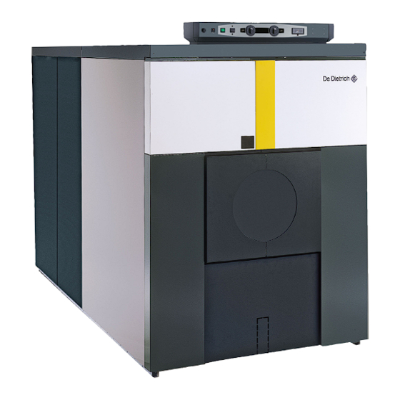
- Page 1 Oil/Gas-Fired Near-Condensing Hot Water Boiler De Dietrich GT 530A and GT530AE Series Assembly, Installation and Service Manual Product may not be exactly as shown. www.dedietrichboilers.com DDR_G30A/AE _ISM_V4.0 03/2014...
- Page 2 Guideline of Notices Safety Considerations Please observe the following safety instructions. Warning: indicates presence of hazards that can cause, if not Read this manual carefully. avoided, severe personal injury, death or substantial Correct installation and adjustment of the burner and the control property damage.
-
Page 3: Table Of Contents
Contents Contents ..................3 Regulations and guidelines . -
Page 4: Regulations And Guidelines
Regulations and guidelines The installation and operating instructions shown here are given as a Only a qualified and licenced heating professional is to carry out the guide for installation and operation and are not meant to replace any removal, installation, startup and maintenance of this boiler. The boiler must State or Local Codes that may apply to the individual installation. -
Page 5: Safety And Warranty Information
Safety and Warranty Information Symbols used Read this manual carefully before installing the boiler or putting it into operation. This manual must be retained for future reference. If the information in this manual is not followed exactly, a fire or explosion may result causing property/product damage, serious personal injury and possibly death. -
Page 6: Safety Information
Safety Information Operation cause injury or death. Blocked or partially blocked chimneys must have the blockage removed by a Before operating the boiler, make sure you fully qualified heating contractor. understand its method of operation. Your heating • Check pressure gauge for correct system (water) contractor should always perform the initial start-up pressure. -
Page 7: Safety Information And Codes
Safety Information and Codes Codes CAUTION Installation, servicing and maintenance of this product The operator/ultimate owner is required to have the must be performed by a licenced and trained heating heating boiler, burners, and controls checked, as a contractor, experienced in hot water heating boilers as minimum once per year, by the original installer or well as gas and oil combustion. -
Page 8: Requirements For Installation In The State Of Massachusetts
Regulations and guidelines Requirements for installation in the state of Massachusetts Boiler Installations within the Commonwealth of Massachusetts must conform to the following requirements: • Boiler must be installed by a plumber or a gas fitter who is licensed within the Commonwealth of Massachusetts. -
Page 9: Requirements For Installation In The State Of Massachusetts (Continued)
Regulations and guidelines Requirements for installation in the state of Massachusetts (continued) 4. INSPECTION: The state or local gas inspector of the side wall horizontally vented gas fueled equipment shall not approve the installation unless, upon inspection, the inspector observes carbon monoxide detectors and signage installed in accordance with the provisions of 248 CMR 5.08(2)(a)1 through 4. -
Page 10: Safety Information And Codes
Safety Information and Codes Water pipe freezing hazard Combustion sources and ventilation air contaminants WARNING Contaminants are likely to be found in these areas: Serious property damage and/or personal injury can • Auto body shops occur if the pipes are not protected from •... - Page 11 General Information Eutectic ® cast iron boiler Large wiring duct Control panel designed body, thermal shock and leading to the to enable easy wiring corrosion resistant,allowing control connections low modulated temperature panel operation and complete stop between heating periods Sensor well Flue nozzle with two Silicone wrapped cleaning traps...
-
Page 12: Technical Specifications
Technical Specifications Boiler Model Gt 530A Series Item Unit Firing Sequence Sonsult Burner Technical Data 3,749 3,966 4,254 4,470 4,759 4,975 5,191 5,480 5,696 5,984 6,201 Gas Input (CSA) 1,099 1,162 1,274 1,310 1,395 1,458 1,521 1,606 1,669 1,754 1,817... - Page 13 Technical Specifications Boiler Model Gt 530AE Series Item Unit Firing Sequence Sonsult Burner Technical Data 6,483 6,652 6,825 7,166 7,505 7,849 8,190 Gas Input (CSA) 1,900 1,950 2,000 2,100 2,200 2,300 2,400 # 2 Fuel Oil Input (CSA) US GPH 43.8 45.8 47.7...
- Page 14 Technical Specification GT 530A and GT 530AE (1) Boiler Supply 5” ANSI 150# welded neck flange (4) 1/2” NPT port for temperature and pressure gauge (2) Boiler return, 5” ANSI 150# welded neck flange (5) 3/4” NPT port for low water cut-off control (LWCO) (3) Drain, 3/4”...
-
Page 15: Clearances
Installation Specification Clearances CAUTION The GT 530A/AE boiler has a sturdy underframe, Do not install boiler on combustible flooring or carpet. it does not need any special base although a house Clearance shown are to combustible materials and ser- keeping pad is recommended to keep steel parts out vicing. -
Page 16: Combustion Air
Installation Specification Combustion Air Requirements • Beauty shops • Paint shops WARNING • Agricultural • Inadequate combustion air supply will result in carbon monoxide [CO] development • Green houses • Ensure boiler room is provided with an obstruction free combustion air sources. •... -
Page 17: Piping
Installation Specifications Piping water supply flange: 5” Water return flange : 5” GT530A GT530AE -1.22" -1.18" -0.354" -0.315" 0.512" -1.417" -1.378" -0.551" -0.512" 0.315" 0.354" 1.81" 1.85" -1.65" -0.83" -0.83" -0.196" -0.196" 58.58" 58.58" 58.58" 59.2" 59.2" 59.2" 59.2" 59.2" 59.2"... -
Page 18: Recommendations
Installation Specifications Recommendations • The installation must be made in accordance with medium is piped in parallel with the boiler with the codes in effect. appropriate valves to prevent the chilled medium • An expansion tank has to be connected to the from entering the boiler system Safety valve must be connected to the •... -
Page 19: Replacement Procedures
Installation Specifications Replacement procedures _ _ _ _ _ _ _ _ _ _ _ _ _ _ _ _ _ _ _ _ _ _ _ _ _ _ _ _ _ _ _ _ _ _ _ _ _ _ _ _ _ _ _ _ _ _ _ _ _ _ _ _ _ _ _ _ _ _ _ _ _ _ _ _ _ _ _ _ _ _ _ _ _ _ _ _ _ _ _ _ _ _ _ _ _ _ _ _ _ _ _ _ _ _ _ _ _ _ _ _ _ _ _ _ _ _ _ _ _ _ _ _ _ _ _ _ _ _ _ _ _ _ _ _ _ _ _ _ _ _ _ _ _ _ _ _ _ _ _ _ _ _ _ _ _ _ _ _ _ _ _ _ •... - Page 20 Installation Specifications Dimensional information required for connection of the boiler _ _ _ _ _ _ _ _ _ _ _ _ _ _ _ _ _ _ _ _ _ _ _ _ _ _ _ _ _ _ _ _ _ _ _ _ _ _ _ _ _ _ _ _ _ _ _ _ _ _ _ _ _ _ _ _ _ _ _ _ _ _ _ _ _ _ _ _ _ _ _ _ _ _ _ _ _ _ _ _ _ _ _ _ _ _ _ _ _ _ _ _ _ _ _ _ _ _ _ _ _ _ _ _ _ _ _ _ _ _ _ _ _ _ _ _ _ _ _ _ _ _ _ _ _ _ _ _ _ _ _ _ _ _ _ _ _ _ _ _ _ _ _ _ _ _ _ _ _ _ _ _ _ _ GT530A GT530A -0.04 0.99...
- Page 21 Assembly + Set up Assemble the boiler body from the rear to the front : - assemble the rear section, - assemble all the normal intermediate sections, - assemble all the special intermediate sections, - assemble the front section. The number of sections of each type is provided in the table below Rear Section Normal intermediate...
- Page 22 Assembly + Set up Boilers : 14, 16, 18, 20, 22, 24 sections Boilers : 15, 17, 19, 21, 23, 25,26, 27,28, 29,30, 31,32 sections Establish the location of the frame on the basis of the opening direction of the boiler door and the length of the burner. ...
- Page 23 Assembly + Set up Handle the nipples with gloves as there might be sharp edges. Remove any traces of rust protective paint with a fine to medium wire wheel so that the surface is perfectly smooth. Coat with the nipple coating with the sections. Gently push in the 2 nipples.
- Page 24 Assembly + Set up Fill the bottom of the W groove opposite the U groove for the intermediary parts (located on the periphery of the section) with a continuous bead of DOW CORNING silicone, approximately Ø 3 /16” / 5 mm diameter. 1 Rear section 2 Intermediate section Place the first normal intermediate section, making sure that it is turned in the right direction, i.e.
- Page 25 Assembly + Set up Put the assembly tool in position. Tighten gradually so as to bring together the upper and lower connections evenly and simultaneously. Assemble the remaining intermediate sections one by 3-10 one according to the procedure in step First assemble the normal intermediate sections, then ...
- Page 26 Assembly + Set up Trim off any projecting ends of the thermocords flush with the coast sections. 10. Fitting the upper and lower assembly rods On the lower assembly rods, fit the following at each end in the given order : an expansion spring, a washer and a nut ...
- Page 27 Assembly + Set up Rear Front Put in place the upper assembly rods in the two front and rear lugs. For 26-32 sections boilers, the provided extension and coupling (M14 x 42mm) will be required. Mount the 2 crosspieces (supplied in package MR245/246) with their bends turned backwards and fasten them to the ...
- Page 28 Assembly + Set up 12. Assembling the side assembly rods The side assembly rods must be assembled from the Place the expansion spring and washer on the rear of rear to the front. each rod. The rods must be inserted in the holes stated in the Stop tightening the nuts as soon as the gap between ...
- Page 29 Assembly + Set up 1/2” 1/2” 1/2” /520mm /520mm /520mm 1/2” 1/2” /420mm /420mm 1/2” 1/2” 1/2” /520mm /520mm /520mm 1/2” 1/2” /420mm /420mm GT 530A-18 1/2” /520mm 1/2” 1/2” /520mm /520mm 1/2” /520mm 1/2” /420mm 1/2” 1/2” 1/2” /520mm /520mm /520mm 1/2”...
- Page 30 Assembly + Set up 1/2” 1/2” 1/2” /520mm /520mm /520mm 1/2” 1/2” 3/16” /420mm /520mm /385mm 1/2” 1/2” 1/2” /520mm /520mm /520mm 1/2” 1/2” 3/16” /420mm /520mm /385mm GT 530A-21 1/2” 1/2” 1/2” /520mm /520mm /520mm 1/2” 1/2” /520mm /520mm 3/16”...
- Page 31 Assembly + Set up 1/2” 1/2” 1/2” 1/2” /420mm /520mm /520mm /520mm 1/2” 1/2” /520mm 3/16” /420mm /385mm 1/2” /420mm 1/2” 1/2” 1/2” /520mm /520mm /520mm 1/2” 1/2” /520mm /420mm 3/16” /385mm GT 530A-24 1/2” 1/2” 1/2” 1/2” /420mm /520mm /520mm /520mm 1/2”...
- Page 32 Assembly + Set up 3/5” /320mm 1/2” 3/16” 1/2” /520mm /385mm /520mm 1/2” 1/2” /520mm /520mm 1/2” 1/2” /420mm /520mm 1/2” 1/2” 3/16” /520mm /520mm /385mm 3/5” /420mm 1/2” /520mm 1/2” 1/2” /520mm /520mm 1/2” /420mm GT 530-27 GT 530AE-27 1/2”...
- Page 33 Assembly + Set up 3/16” /385mm 1/2” 1/2” /520mm 1/2” /520mm /520mm 1/2” /520mm 1/2” /520mm 1/2” 1/2” /520mm /520mm 3/16” /385mm 1/2” 1/2” 1/2” /520mm /520mm /520mm 1/2” /520mm 1/2” /520mm 1/2” 1/2” /520mm /520mm GT 530-30 GT 530AE-30 3/16”...
- Page 34 Assembly + Set up 13. Assembling the pocket and the plugs GT 530A 15-19 Front GT 530A 20-32 Assemble the well for the thermostats and thermometer in : The third special intermediate section -5 ” wide, 1/2’’ hole for GT 530A-15 to GT 530A-19 15/16 the fourth special intermediate section - 5 ”...
- Page 35 Assembly + Set up 14. Hydrostatic Test After assembling the boiler body, the installer must carry out a water tightness test at a pressure equal to 1.5 times the operating pressure (that is 135 Psig Max. of 145) a minimum 20 minutes. The test must be done at room temperature with a city water tempreature not less than 60°f/15°C.
- Page 36 Assembly + Set up Assembling the baffle Boiler GT 530A -15 to 19 GT 530A-20 to 25 Total number of baffles Package no. CM 22 + CM 23 2XCM 23 Boiler GT 530AE -26 to 28 GT 530AE-29 to 32 Total number of baffles Package no.
- Page 37 Assembly + Set up Each cover is fitted with a system whereby it Assembling the sweeping Covers can only be mounted with the handles turned outward. The covers are numbered from 1 to 4, and must be fitted with thermocord. The length of the thermocord depends upon the cover and is given below.
- Page 38 Assembly + Set up Insert the thermocord in the sealing groove on each side and hold it in place with a few drops of silicone filler. 20. Installing the lower trap Cleaning Insert the thermocord in the sealing groove of the 2 lower flue ways, on the rear and front of the boiler. ...
- Page 39 Assembly + Set up 21. Installing the burner/boiler door 1 2 screws SIM 3.94x25.4 2 Refractory felt 3 Rigid refractory plate - Put the furnace door insulating material in place and retain it with the 4 screws SIM 3.94x25.4. - Place the burner/boiler door on the floor and fasten the door hinge onto the door with 3 screws HM 12.
- Page 40 Assembly + Set up Fit the door onto the hinge by inserting the pin. Close the burner door on the 8 studs and fasten with 8 washers and nuts. Instal the 2 Cleaning doors of the upper flue ways and fasten with the wing nuts.
- Page 41 Assembly + Set up 25. Flame inspection window Flame inspection window The flame inspection window is fitted with a 1/4” tapped hole for chamber pressure measurements and block vent chamber device. 26. Assembling the return lange on GT 530A-15 to GT 530AE-32 Fit the water balancing tube onto the boiler return ...
- Page 42 Assembly + Set up 26. Assembling the supply lange on GT 530A-15 to Gt 530AE-32 GT 530A-15 Package FA111 Package FA112 to FA121 GT 530A-16 to GT 530A-25 GT 530AE-26 to GT 530AE-32 Package FA126B to FA132B • GT 530A-15 1/16”...
- Page 43 Assembly + Set up Before assembling the flue gas box, grease all bolts, studs and screws with high-temperature grease (field supplied). Put in place the thermocord . Put the sweeping cover in place and fasten with 2 nuts H10 and Ø...
- Page 44 Assembly and Set up 32. Installing the top insulating material (FA30 to FA36) GT 530A-15 to Gt 530A-17 2 Front 5/8” Put in place the 23 600mm mm wide (packages FA35 to FA36) top insulating material on the body of the boiler Number of section GT 530A-15+16 GT 530A-17...
- Page 45 Assembly + Set up 34. Installing the top insulating material (FA37 to FA41) GT 530A-18 to Gt 530AE-32 Put in place the 2 pieces of insulating material (width 600 mm; packages FA37 to FA41) on the body of the boiler. ...
- Page 46 Assembly and Set up 36. Installing the cable channels (FA16 To FA24) GT 530A-18 to Gt 530A-25 Package FA16 Package FA17 to FA24 GT 530AE-26 to Gt 530AE-32 Package FA18-FA24-Mount Package FA24-Reversed Front GT 530A Number of sections 102 . 37”/2,600 122 .
- Page 47 Assembly + Set up 38. Installing the lower rail support brackets (MA245 or MA 246) • Example for a GT 530A Fasten the lower rail support brackets using H8 x 16 screws + Serrated washer. Note: For the assembly direction, see the following drawings 39.
- Page 48 Assembly and Set up GT 530A-17 Right Side Rail Support brackets Base Frame Left Side GT 530A-18 and GT 530A-20 Right Side Rail Support brackets Left Side GT 530A-19 and GT 530A-21 Right Side Rail Support brackets Left Side GT 530A-22 and GT 530A-24 Right Side Base Frame Rail Support brackets...
- Page 49 Assembly and Set up GT 530A-23 and GT 530A-25 Right Side Rail Support brackets Base Frame Left Side GT 530AE-26 /27/28/29/32 Right Side Rail Support brackets Base Frame Left Side GT 530AE-30 /31 Right Side Rail Support brackets Base Frame Left Side DDR_G30A/AE _IO_V4.0 09/2013 GT 530A...
- Page 50 Assembly + Set up 40. Installing the lower rail support brackets (FA17 to FA27) GT 530A-18 and GT 530A-20 Fasten the lower rail with H8 x 30 screws and L8 washers. The other rail support brackets are fastened opposite the holes provided on the lower rail.
- Page 51 Assembly and Set up 42. Fitting the rails (FA17 to FA27) Front Front A : GT 530A-15 to GT 530A-17 Package Package Fix the upper rail with H8 x 30 screws and L8 washers Boiler (the first hole from the front end of the rail must be GT 530A-15 FA 25 opposite the first fastening bracket, and similarly with...
- Page 52 Assembly + Set up 43. Installing the insulation Place the side insulating material against the positioning bracketand cut it so that it is flush with the upper lug Front on which the rail fastening bracket is fixed, along a 1/2” /220mm length.
- Page 53 Assembly and Set up 1. First assemble the panels on the front side using the assembly length table below and continue up to the rear section. 2. Fix the front side panels to the positioning brackets with H8 x 16 screws and serrated washers. 3.
- Page 54 Assembly + Set up Installing the boiler door and lower crosspiece bracket (MR 245 or MR 246) 1. Put the boiler door in place (package MR245 or MR246) and fasten with 2 tapping screws (Ø 3.94 x 12.7). The boiler door may be cut in 2 at the micro-joints. 2.
- Page 55 Assembly and Set up 47. Standard control panel (MD5 and MR246) Put the front crosspiece in place (package MR245 or MR246) and fasten with 2 screws (H8x30) and Ø 3.94 tapping screws ( x 12.7) and serrated washers. 48. Installing the MD5 control panel Rear View Front View 1.
- Page 56 Assembly + Set up 49. Electrical Connections All connections are made with the terminal boxes designed for that purpose on the back of the boiler's control panel Bring the burner cable behind the casing support and down to the burner between the side panel and insulating material.
- Page 57 Assembly and Set up 51. Installing lower front side panels (MR245 or 246) 52. Installing the front top panel (MR245 or MR246) Place the retaining crosspiece on the left and right-hand front panels, taking care to place the 2 central tabs behind the ...
- Page 58 Assembly + Set up 53. Installing the Fluegas box insulation (MR245 or 246) Install in place the flue gas box insulation and the lower rear insulation. If the side crosspieces overlap at the rear by more than 7/8”/10mm, we advise you to saw them off using a hacksaw. ...
- Page 59 Assembly and Set up 55. Installing the rear casing panel (MR245 or 246) 1. Attach the 2 clip-on nuts on the side panels. 2. Attach the upper rear panel onto the studs and push it up. 3. Fasten with 2 screws H8 x 16 and serrated washers. 4.
- Page 60 Assembly + Set up 57. Installing the side covers GT 530A-18 to Gt 530A-25 Package FA17 to FA24 Package MR246 Package FA16 1. Position the rear plate, which is 47 /1200 mm long. Attach 2 screws H8 x 30 and serrated washers. 2.
- Page 61 Assembly and Set up 56. Installing the side Covers (FA5 to FA11) Package FA8 to FA9. Package FA10 to FA11 Place the side covers from the front to rear. They have the same lengths as the side panels. Boiler Type Side panels (in/mm) Front Rear...
- Page 62 Connections Oil or gas connections Specific technical information supplied with the • Provision for vent, bleed and gas relief lines (when burner applicable). • The boiler and its individual shutoff valve must be • A sediment trap must be provided upstream of the disconnected from the gas supply piping system gas controls.
- Page 63 Connections Burner installation on boiler burner door Typical flush to recessed combustion Typical protruding combustion head position application head position application E° Overall diameter including gap between head Degree of tapper required on refactory material and refratory material, including tappering to allow proper flame pattern Burner combustion head diameter (consult Maximum position combustion head shall be...
- Page 64 Connections De Dietrich Cast Iron Boiler Temperature Controller Model S3NA (standard version) OVERVIEW OF COMPONENTS S3NA Safety Hi-Limit (Manual Reset) Fixed Setting WARNING 120°C [248°F] • All replacement and field wiring min 18awg. Type Panel fuse protection (resettable-breaker) 250v TEW or 1015 CSA/UL approved. 10A rated •...
- Page 65 Burner main power 120/60/1 Limit Circuit Main Power 120/60/1 DDR_G30A/AE _IO_V4.0 09/2013 GT 530A GT 530A DDRA 001 v1.0 06/2010...
- Page 66 DDRA 001 v1.0 06/2010 GT 530A...
- Page 67 DDR_G30A/AE _IO_V4.0 09/2013 GT 530A GT 530A DDRA 001 v1.0 06/2010...
- Page 68 DDRA 001 v1.0 06/2010 GT 530A GT 530A DDR_G30A/AE _IO_V4.0 09/2013...
- Page 69 DDR_G30A/AE _IO_V4.0 09/2013 GT 530A GT 530A DDRA 001 v1.0 06/2010...
- Page 70 Connections Filling the system CAUTION Filling shall be performed with a low flow rate from a low point in the boiler room in order to ensure that all Instructions for starting up the boiler for the first the air in the boiler is bled from the high point of the time after the system is fully or partly drained: system.
-
Page 71: Contents
Venting Boiler breeching and main chimney De Dietrich GT Series boilers are a high performance boiler. The flue gas temperature can be less than 320°F [160°C]. Special attention is required for the venting of the boiler according to the specific site operating conditions. - Page 72 Gas Vent Category I - High Temperature Operation Applications: Consult a chimney-venting specialist or professional engineer for the sizing of the breeching and main chimney in accordance to local and national gas codes CSA B149.1-05 & ANSI Z223.1 (NFPA 54) and sized accordingly to the appropriate tables or methods of chimney vent sizing as local jurisdiction will accept.
- Page 73 Application Note: it is mandatory that a vent safety device be employed, either equipped on burner or venting (gas, combustion head or vent pressure switch) APPLICATION NOTE: (Other than Sidewall or Direct Vent, sealed combustion air applications) All venting systems must be sized by experienced venting specialists using available codes or by acceptable engineering methods, a final sizing sheet of the venting and calculation must show how the venting was sized and designed.
-
Page 74: Oil Or Gas Connection
Oil or gas connections 1 Specific technical information supplied with the jacket when codes require. burner Electrical • The boiler and its individual shutoff valve must be 1-Wiring disconnected from the gas supply piping system Wiring in accordance with the requirements of the au- during any pressure testing of that system at test thority having jurisdiction or, in the absence of such re- pressures in excess of 1/2 psi (3.5kPa),... -
Page 75: Start Up Procedures
Start up procedures FOR YOUR SAFETY READ BEFORE OPERATING phone in your building. • Immediately call your gas supplier from a WARNING: neighbor’s phone. Follow the gas supplier’s If you do not follow these instructions ex- instructions. actly, a fire or explosion may result causing •... -
Page 76: Maintenance
Maintenance Boiler _ _ _ _ _ _ _ _ _ _ _ _ _ _ _ _ _ _ _ _ _ _ _ _ _ _ _ _ _ _ _ _ _ _ _ _ _ _ _ _ _ _ _ _ _ _ _ _ _ _ _ _ _ _ _ _ _ _ _ _ _ _ _ _ _ _ _ _ _ _ _ _ _ _ _ _ _ _ _ _ _ _ _ _ _ _ _ _ _ _ _ _ _ _ _ _ _ _ _ _ _ _ _ _ _ _ _ _ _ _ _ _ _ _ _ _ _ _ _ _ _ _ _ _ _ _ _ _ _ _ _ _ _ _ _ _ _ _ _ _ _ _ _ _ _ _ _ _ _ _ _ _ _ _ It is not advisable to drain an installation, except in The good performance of the boiler depends case of absolute necessity. - Page 77 - Remove the baffle plates from the upper flue ways. - Carefully brush the four flue ways with the brush supplied for that purpose. - Brush the baffle plates as well. - If possible, use a vacuum cleaner. - Remove the left and right-hand casing covers. - Remove the top insulation.
- Page 78 Unscrew the eight closing nuts and open the burner. Brush out the inside of the furnace. Clean the soot accumulated in the burner and lower These screws must not be unfastened in any flue ways witha vacuum cleaner. event. Close the lower cleaning doors. Put back the front casing panels by reversing the removal procedure.
-
Page 79: Service And Maintenance Schedule
5.5 All Side-wall and direct Vent termination locations installation precautions: _ _ _ _ _ _ _ _ _ _ _ _ _ _ _ _ _ _ _ _ _ _ _ _ _ _ _ _ _ _ _ _ _ _ _ _ _ _ _ _ _ _ _ _ _ _ _ _ _ _ _ _ _ _ _ _ _ _ _ _ _ _ _ _ _ _ _ _ _ _ _ _ _ _ _ _ _ _ _ _ _ _ _ _ _ _ _ _ _ _ _ _ _ _ _ _ _ _ _ _ _ _ _ _ _ _ _ _ _ _ _ _ _ _ _ _ _ _ _ _ _ _ _ _ _ _ _ _ _ _ _ _ _ _ _ _ _ _ _ _ _ _ _ _ _ _ _ _ _ _ _ _ _ _ - The boiler and the chimney must be carefully cleaned. - Page 80 Spare parts - GTE 530A While ordering spare parts, do not forget to provide the code number given in the list opposite the part reference. BOILER BODY GT 530A DDR_G30A/AE _IO_V4.0 09/2013...
- Page 81 Insulation DDR_G30A/AE _IO_V4.0 09/2013 GT 530A...
- Page 82 GT 530A DDR_G30A/AE _IO_V4.0 09/2013...
- Page 83 DDR_G30A/AE _IO_V4.0 09/2013 GT 530A...
- Page 84 Ref. Code no. DESCRIPTION Ref. Code no. DESCRIPTION BOILER BODY + ACCESSORIES 9755-0236 Burner door insulation 8008-8915 Burner plate hinge 30000-6597 Complete frame 15 sections Bag of screws for cleaning doors 8555-8592 30000-6598 Complete frame 16 and 17 sections 30000-6599 Complete frame 18 and 19 sections 8555-5528 Flue gas outlet + braid...
- Page 85 Ref. Code no. DESCRIPTION Ref. Code no. DESCRIPTION 21/64” INSULATION 8555-8052 long right-hand wiring duct 55/64” Insulation for body 8555-8053 long right-hand wiring duct 13/64” 8555-5521 Complete insulation for body, 15 sections 8555-8054 long right-hand wiring duct 8555-5522 Complete insulation for body, 16 and 17 sections 7/64”...
- Page 86 8555-8508 37” long right-hand upper front plate for cleaning ”1/3 8555-8509 long right-hand upper front plate for cleaning 8555-8511 37” long left-hand upper front plate for cleaning 1/3” 8555-8512 long left-hand upper front plate for cleaning Rear side casing 3/4” 8555-8500 rear side panel 5/8”...
Need help?
Do you have a question about the GT 530A Series and is the answer not in the manual?
Questions and answers