Table of Contents
Advertisement
Quick Links
Advertisement
Table of Contents

Subscribe to Our Youtube Channel
Related Manuals for AMX Modero X-Series G5


Summary of Contents for AMX Modero X-Series G5
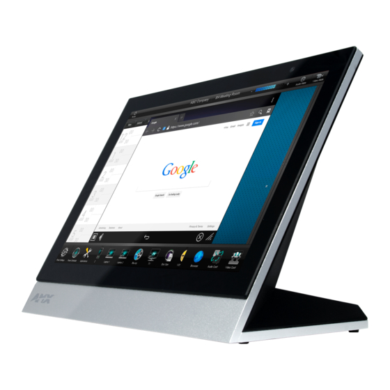
- Page 1 I n s t r u c t i o n M a n u a l Modero X-Series G5 Panoramic Touch Panels MXT/D-2001-PAN - 20.3" Modero X Series G5 Panoramic Touch Panels MXT/D-1901-PAN - 19.4" Modero X Series G5 Panoramic Touch Panels...
- Page 2 AMX is not responsible for products returned without a valid RMA number. AMX is not liable for any damages caused by its products or for the failure of its products to perform. This includes any lost profits, lost savings, incidental damages, or consequential damages.
-
Page 3: Table Of Contents
Table of Contents Table of Contents Modero X Series G5 Panoramic Touch Panels (20.3" & 19.4") ......1 Overview ........................1 Sleep Button ......................2 Powering On/Off X Series G5 Panels................ 2 Configuration and Programming ................2 Bluetooth Support ....................3 NFC Support...................... - Page 4 Table of Contents Wiring a Power Connection................... 43 Uninstalling the MXD-1901-PAN................44 Removing an MXD-1901-PAN From Its Backbox............44 Upgrading Firmware ..................45 Overview ........................ 45 Upgrading Firmware via USB Flash Drive ............... 45 Load the Firmware on a USB Flash Drive ..............45 Transfer the Firmware File From the Flash Drive to the Touch Panel......
-
Page 5: Modero X Series G5 Panoramic Touch Panels (20.3" & 19.4")
Modero X Series G5 Panoramic Touch Panels (20.3" & 19.4") Modero X Series G5 Panoramic Touch Panels (20.3" & 19.4") Overview The most elegant interface designed specifically for dedicated room control has been significantly enhanced to include a new G5 Graphic Engine to provide even faster and smoother animations and transitions, and we quadrupled the processing power with a new Quad Core Processor. -
Page 6: Sleep Button
Modero X Series G5 Panoramic Touch Panels (20.3" & 19.4") Sleep Button X Series G5 touch panels are operated using its integral touchscreen, as well as the Sleep button. The Sleep button is located in the in the center of the top panel of the device for tabletop and landscape wall-mount panels; it is located in the center of the left panel for portrait panels (see FIG. -
Page 7: Bluetooth Support
Modero X Series G5 Panoramic Touch Panels (20.3" & 19.4") Information on the Settings menu, panel configuration, and programming is included in the Modero X Series G5 Programming Guide, available at www.amx.com. Programming the Modero X Series G5 touch panels require the use of the latest versions of NetLinx Studio and TPDesign5, both available to download at www.amx.com. -
Page 8: Active Video Windows - Limitations
FIG. 6 shows an AMX device installed in a wall with a filled volume (such as with insulation or concrete), as well as with a closed volume (such as between studs in an otherwise finished wall). The diagram shows how heat generated by the device or other devices may have no way to escape, and may build up to levels that may affect device operation. - Page 9 Heat convection in filled or closed volume, limited or no convection In FIG. 7, the diagram displays an AMX device in a typical rack mounting, with full air circulation around the front and back of the device. In this case, the main concern is with heat building up between components, possibly to levels that may affect device operation.
-
Page 10: Installation Recommendations
Modero X Series G5 Panoramic Touch Panels (20.3" & 19.4") Installation Recommendations During any installation, a lack of ventilation may produce conditions that may adversely affect the device’s operation. In these circumstances, special care must be made to make sure that temperatures within enclosed areas do not exceed the device’s maximum rated temperature. -
Page 11: Mxt/D-2001-Pan - 20.3" X Series G5 Panels
Full-On: 35 W (12 VDC, 2.9 A) Standby: 7 W (12 VDC, 0.6 A) EXTERNAL POWER Requires one of these AMX power sources (not included): SUPPLY REQUIRED • PSN4.4 Power Supply, 4.4 A, 3.5 mm Phoenix, 13.5 VDC (FG423-45) • PSR4.4 Power Supply, 4.4 A, 3.5 mm Phoenix with Retention Screws (FG423-46) •... - Page 12 • Intercom*: Full Duplex VoIP, SIP v2.0 GRAPHICS ENGINE AMX G5: G5 enhanced feature set supporting multi-touch and gestures, scrolling, transitions, applications - See TPD5 Operations Guide for more information EMBEDDED APPLICATIONS • Viewer Applications*: PDF, JPEG, BMP, PNG, TIFF, GIF •...
- Page 13 MXT/D-2001-PAN - 20.3" X Series G5 Panels MXT-2001-PAN Specifications (Cont.) FRONT PANEL • Light Sensor: Photosensitive light detector for automatic adjustment of the panel COMPONENTS brightness • Proximity Detector: Max range = ~3', typ range = ~1', FOV = ~10 degrees •...
-
Page 14: Mxt-2001-Pan Installation
MXT/D-2001-PAN - 20.3" X Series G5 Panels MXT-2001-PAN Installation Detailed specifications drawings for the MXT-2001 are available to download from www.amx.com. FIG. 9 MXT-2001-PAN Connector Locations Two Type A USB ports are located on the rear right corner of the device (FIG. 10). -
Page 15: Wiring Guidelines
MXT/D-2001-PAN - 20.3" X Series G5 Panels The power and Ethernet connectors, as well as an additional USB port are located on the bottom of the device ( FIG. 11). The underside USB port, as well as the two rear USB ports, may be used with a flash drive for page transfers or firmware upgrades. -
Page 16: Mxd-2001-Pan (Wall-Mount - Portrait/Landscape)
MXT/D-2001-PAN - 20.3" X Series G5 Panels PWR + Power Supply GND - To the Touch Panel FIG. 13 NetLinx power connector wiring diagram Insert the PWR and GND wires on the terminal end of the 2-pin 3.5 mm captive wire cable. Match the wiring locations of the +/- on both the power supply and the terminal connector. -
Page 17: Mxd-2001-Pan Specifications
• Full-On: 35 W (12 VDC, 2.9 A) • Standby: 7 W (12 VDC, 0.6 A) EXTERNAL POWER Requires one of these AMX power sources (not included): SUPPLY REQUIRED • PSN4.4 Power Supply, 4.4 A, 3.5 mm Phoenix, 13.5 VDC (FG423-45) •... - Page 18 • Intercom*: Full Duplex VoIP, SIP v2.0 GRAPHICS ENGINE AMX G5: G5 enhanced feature set supporting multi-touch and gestures, scrolling, transitions, applications - See TPD5 Operations Guide for more information EMBEDDED APPLICATIONS • Viewer Applications*: PDF, JPEG, BMP, PNG, TIFF, GIF •...
- Page 19 MXT/D-2001-PAN - 20.3" X Series G5 Panels MXD-2001-PAN Specifications (Cont.) ENVIRONMENTAL • Temperature (Operating): 32° F to 104° F (0° C to 40° C) • Temperature (Storage): 4° F to 140° F (-20° C to 60° C) • Humidity (Operating): 20% to 85% RH •...
-
Page 20: Mxd-2001-Pan Installation
MXD-2001-PAN Installation Detailed specifications drawings for the MXD-2001-PAN are available to download from www.amx.com. Refer to A Note About Wall and Rack Installation on page 4 for important notes on thermal concerns with Rack and Wall installations. The MXD-2001-PAN may be installed directly into a solid surface environment, using either solid surface screws or the included locking tabs for different mounting options. - Page 21 MXT/D-2001-PAN - 20.3" X Series G5 Panels Note: Dimensions in parenthesis are in millimeters FIG. 17 MXD-2001-PAN In order to ensure a stable installation of the MXD-2001-PAN, the thickness of the wall material must be a minimum of .50 inches (1.27cm) and a maximum of .875 inches (2.22cm).
-
Page 22: Installing The Backbox
MXT/D-2001-PAN - 20.3" X Series G5 Panels Installing the Backbox Note: Dimensions in parenthesis are in millimeters FIG. 18 MXD-2001-PAN-L Installation Dimensions (front view) Note: Dimensions in parenthesis are in millimeters FIG. 19 MXD-2001-PAN-L Installation Dimensions (side view) Since the cutout for the Backbox is off-center from the edges of the touch panel, use the included Installation Template (68-5968-01) to ensure proper placement (FIG. - Page 23 MXT/D-2001-PAN - 20.3" X Series G5 Panels 20.433" (519.00 mm) 14.50" (368.30 mm) 5.69" (144.50 mm) 9.53" (242.00 mm) FIG. 20 20.3" Installation Template Prepare the area by removing any screws or nails from the drywall before beginning the cutout process. After ensuring proper placement, cut out the mounting surface for the Backbox, using the included Installation Template as a guide.
- Page 24 MXT/D-2001-PAN - 20.3" X Series G5 Panels Cables Routed to Wall Opening Wall 4X Installation Clamp for Wall Thickness .37 [12.01] to .98 [25.0] 8X Knock Outs Mounting screws Remove For Cable Routing As Needed placement (optional) FIG. 21 MXD-2001-PAN Backbox installation (Landscape) MXD/T-2001-PAN and MXD/T-1901-PAN Modero X Series®...
- Page 25 MXT/D-2001-PAN - 20.3" X Series G5 Panels Cables Routed To Locking tab Wall Opening Wall 8X Knock Outs Remove For Cable Routing As Needed 4X Installation Clamp for Wall Thickness .37 [12.01] to .98 [25.0] Mounting screws placement (optional) FIG. 22 MXD-2001-PAN Backbox installation (Portrait) Remove any knockouts as needed on either long dimension of the Backbox (FIG.
- Page 26 MXT/D-2001-PAN - 20.3" X Series G5 Panels 12 VDC Power Port Ethernet 10/100 Port Type A USB Port (limited access) FIG. 23 MXD-2001-PAN rear connectors Test the incoming wiring by attaching the panel connections to their terminal locations and applying power. Verify that the panel is receiving power and functioning properly to prevent repetition of the installation.
- Page 27 MXT/D-2001-PAN - 20.3" X Series G5 Panels Side cover 6X 4-40 X 1/4" LONG FLAT HEAD TORQUE TO 5±.2 IN LBS Wall 4X Mounting post openings Side cover FIG. 25 MXD-2001-PAN installation (Portrait) When installing the panel, do NOT press on or near the center of the panel. Too much stress at the center may damage the touch screen surface.
-
Page 28: Wiring A Power Connection
MXT/D-2001-PAN - 20.3" X Series G5 Panels Side cover Screws (3) FIG. 26 MXD-2001-PAN side cover installation (Landscape) Snap the decorative side covers (FIG. 26) onto each end of the touch panel. Reconnect the terminal Ethernet and USB to their respective locations on the Ethernet port. Wiring a Power Connection See Wiring a Power Connection on page 24. -
Page 29: Uninstalling The Mxd-2001-Pan
Backbox. Be careful not to pull on the cables or connectors. To reattach the panel to its Backbox, repeat the installation procedure. For further information, refer to the video available at www.amx.com (go to Newsroom > Videos > Touch Panels). - Page 30 MXT/D-2001-PAN - 20.3" X Series G5 Panels MXD/T-2001-PAN and MXD/T-1901-PAN Modero X Series® G5 Panoramic Touch Panels...
-
Page 31: Mxt/D-1901-Pan - 19.4" X Series G5 Panels
• Full-On: 35 W (12 VDC, 2.9 A) • Standby: 7 W (12 VDC, 0.6 A) EXTERNAL POWER Requires one of these AMX power sources (not included): SUPPLY REQUIRED • PSN4.4 Power Supply, 4.4 A, 3.5 mm Phoenix, 13.5 VDC (FG423-45) •... - Page 32 • Intercom*: Full Duplex VoIP, SIP v2.0 GRAPHICS ENGINE AMX G5: G5 enhanced feature set supporting multi-touch and gestures, scrolling, transitions, applications - See TPD5 Operations Guide for more information MXD/T-2001-PAN and MXD/T-1901-PAN Modero X Series® G5 Panoramic Touch Panels...
- Page 33 MXT/D-1901-PAN - 19.4" X Series G5 Panels MXT-1901-PAN Specifications (Cont.) EMBEDDED APPLICATIONS • Viewer Applications*: PDF, JPEG, BMP, PNG, TIFF, GIF • Remote Management: VNC Server • Video Conferencing: Skype • Conferencing: Audio (Full Duplex Intercom*) FRONT PANEL • Light Sensor: Photosensitive light detector for automatic adjustment of the panel COMPONENTS brightness •...
-
Page 34: Mxd-1901-Pan (Wall-Mount - Landscape/Portrait)
• Full-On: 35 W (12 VDC, 2.9 A) • Standby: 7 W (12 VDC, 0.6 A) EXTERNAL POWER Requires one of these AMX power sources (not included): SUPPLY REQUIRED • PSN4.4 Power Supply, 4.4 A, 3.5 mm Phoenix, 13.5 VDC (FG423-45) •... - Page 35 MXT/D-1901-PAN - 19.4" X Series G5 Panels MXD-1901-PAN Specifications (Cont.) CERTIFICATIONS • FCC Part 15 Class B • C-Tick CISPR 22 Class B • CE EN 55022 Class B and EN 55024 • CB Scheme IEC 60950-1 • IC • IEC/EN-60950 •...
- Page 36 • Intercom*: Full Duplex VoIP, SIP v2.0 GRAPHICS ENGINE AMX G5: G5 enhanced feature set supporting multi-touch and gestures, scrolling, transitions, applications - See TPD5 Operations Guide for more information EMBEDDED APPLICATIONS • Applications*: PDF, JPEG, BMP, PNG, TIFF, GIF •...
-
Page 37: Mxt-1901-Pan Installation
* This feature will be available upon release of a future firmware update. MXT-1901-PAN Installation Detailed specifications drawings for the MXT-1901 are available to download from www.amx.com. FIG. 30 MXT-1901-PAN MXD/T-2001-PAN and MXD/T-1901-PAN Modero X Series® G5 Panoramic Touch Panels... -
Page 38: Connector Locations
MXT/D-1901-PAN - 19.4" X Series G5 Panels Connector Locations Two USB ports for peripherals are located on the rear right corner of the device (FIG. 31). Type A USB Ports FIG. 31 MXT-1901-rear view USB peripherals (mouse, keyboard, etc.) may be connected to either of the two USB ports on the rear of the device. The power and Ethernet connectors, as well as an additional USB port are located on the bottom of the device (FIG. -
Page 39: Wiring Guidelines
MXD-1901-PAN Installation Detailed specifications drawings for the MXD-1901-PAN are available to download from www.amx.com. Refer to A Note About Wall and Rack Installation on page 4 for important notes on thermal concerns with Rack and Wall installations. The MXD-1901-PAN may be installed directly into a solid surface environment, using either solid surface screws or the included locking tabs for different mounting options. -
Page 40: Installing The Mxd-1901-Pan Into A Wall
MXT/D-1901-PAN - 19.4" X Series G5 Panels Temporary Mounting Posts Locking Tabs Locking Tabs Temporary Mounting Posts FIG. 35 MXD-1901-PAN Backbox For typical mounting surfaces, such as drywall, use the locking tabs as the primary method for securing the Backbox to the surface. For thin walls or solid surfaces, use mounting screws (not included). - Page 41 MXT/D-1901-PAN - 19.4" X Series G5 Panels Note: Dimensions in parenthesis are in millimeters FIG. 37 MXD-1901-PAN In order to ensure a stable installation of the MXD-1901-PAN, the thickness of the wall material must be a minimum of .50 inches (1.27cm) and a maximum of .875 inches (2.22cm).
-
Page 42: Installing The Backbox
MXT/D-1901-PAN - 19.4" X Series G5 Panels Installing the Backbox FIG. 38 MXD-1901-PAN-L Installation Dimensions (front view) FIG. 39 MXD-1901-PAN-L Installation Dimensions (side view) Since the cutout for the Backbox is off-center from the edges of the touch panel, use the MXD-1901-PAN Installation Template (68-5968-02) to ensure proper placement (FIG. - Page 43 MXT/D-1901-PAN - 19.4" X Series G5 Panels 20.433" (519.00 mm) 14.50" (368.30 mm) 6.89" (175.00 mm) 5.69" (144.50 mm) FIG. 40 MXD-1901-PAN Template Making sure that the actual cutout opening is slightly smaller than the provided dimensions is highly recommended. This action provides the installer with a margin for error if the opening needs to be expanded.
- Page 44 MXT/D-1901-PAN - 19.4" X Series G5 Panels Wall Cables Routed To Wall Opening 8X Knock Outs Remove For Cable Routing As Needed 4X Installation Clamp for Wall Thickness .37 [12.01] to .98 [25.0] Mounting screws placement (optional) FIG. 42 MXD-1901-PAN Backbox installation (Portrait) Remove any knockouts as needed on either long dimension of the Backbox (FIG.
- Page 45 MXT/D-1901-PAN - 19.4" X Series G5 Panels 12 VDC Power Port Ethernet 10/100 Port Type A USB Port FIG. 43 MXD-1901-PAN rear connectors Test the incoming wiring by attaching the panel connections to their terminal locations and applying power. Verify that the panel is receiving power and functioning properly to prevent repetition of the installation.
- Page 46 MXT/D-1901-PAN - 19.4" X Series G5 Panels Side cover 6X 4-40 X 1/4" LONG FLAT HEAD TORQUE TO 5±.2 IN LBS Wall 4X Mounting post openings Side cover FIG. 45 MXD-1901-PAN installation (Portrait) When installing the panel, do NOT press on or near the center of the panel. Too much stress at the center may damage the touch screen surface.
-
Page 47: Wiring A Power Connection
MXT/D-1901-PAN - 19.4" X Series G5 Panels Side cover (X2) Screws (3) FIG. 46 MXD-1901-PAN side cover installation (Landscape) Snap the decorative side covers (FIG. 46) onto each end of the touch panel. Reconnect the terminal Ethernet and USB to their respective locations on the Ethernet port. Wiring a Power Connection See the Wiring a Power Connection section on page 35. -
Page 48: Uninstalling The Mxd-1901-Pan
MXT/D-1901-PAN - 19.4" X Series G5 Panels Uninstalling the MXD-1901-PAN The MXD-1901-PAN is held in place to the Backbox via screws. In certain circumstances, such as firmware updates or other maintenance that requires accessing the device’s USB or Micro-USB ports, the device may need to be removed from the Backbox. -
Page 49: Upgrading Firmware
Overview The latest firmware (*.kit) file for each panel is available to download from www.amx.com. To download firmware files, go to the catalog page for your panel type, and click the link under "Firmware Files" on the right side of the catalog page. -
Page 50: Removing All Data From The Touch Panel
Upgrading Firmware Removing All Data From The Touch Panel To reset the touch panel to its factory defaults and remove all data stored in the device: From the Reset & Update menu, select Factory Data Reset to open the Factory Data Reset window (FIG. 49). FIG. -
Page 51: Resetting To Factory-Installed Firmware
Upgrading Firmware Resetting to Factory-Installed Firmware In certain circumstances, it may be necessary to uninstall the current firmware on a touch panel and return the panel to its original factory default firmware. To reset the touch panel to its original factory firmware: From the Reset and Update menu, select Update Firmware to open the Firmware Update window (FIG. -
Page 52: Installing Previous Firmware
To install new firmware to the touch panel from an external disk via the Settings menu: Download the latest Modero X Series G5 touch panel firmware from www.amx.com and save it to a USB stick or other external drive with USB capability. -
Page 53: Installing Touch Panel Pages From An External Disk
Update Progress display For more information on updating firmware for your touch panel, please refer to the Modero X Series G5 Programming Guide, available at www.amx.com. Installing Touch Panel Pages From an External Disk TPDesign5 page files may be loaded onto a touch panel, both via TPDesign5 and through files saved to a USB-enabled external drive.To load TPD5 pages via USB:... -
Page 54: Removing User Pages From A Touch Panel
Upgrading Firmware FIG. 56 TPDesign5 File Browser window Select the files, and press OK. The pages will be uploaded to the touch panel. Removing User Pages From a Touch Panel In order to remove user pages from a Modero X Series G5 touch panel: From the Reset and Update menu, select Remove User Pages to open the Remove User Pages window (FIG. -
Page 55: Upgrading Firmware Via Netlinx Studio (V3.4 Or Higher)
Upgrading Firmware Upgrading Firmware Via NetLinx Studio (v3.4 or Higher) G5 touch panels use an Ethernet connection for programming, firmware updates, and touch panel file transfer via NetLinx Studio. If you have access to the panel’s network, you may transfer files directly to the panel through NetLinx Studio. - Page 56 Upgrading Firmware FIG. 59 NetLinx Studio v3.4 or higher - Send To NetLinx Device dialog - G5 Firmware file sample Click Send to initiate the firmware file transfer. The progress of the transfer is indicated in the progress bars The Panel will display the Message "Updating System Files", then restart itself. The Installing System Update page will be displayed on the panel until the firmware upgrade process is complete.
- Page 57 Upgrading Firmware File Size Time Required to Complete Transfer (legacy file transfer method) 0-150MB 10 - 15 minutes 150-200MB 15 - 20 minutes 200-250MB 20 - 25 minutes 250-300MB 25 - 30 minutes 300-350MB 30 - 35 minutes >350MB > 35 minutes ...
- Page 58 Upgrading Firmware MXD/T-2001-PAN and MXD/T-1901-PAN Modero X Series® G5 Panoramic Touch Panels...
-
Page 59: Appendix: Troubleshooting
Appendix: Troubleshooting Appendix: Troubleshooting Overview This section describes the solutions to possible hardware/firmware issues that could arise during the common operation of a Modero X Series G5 touch panel. Panel Doesn’t Respond To Touches Symptom: The device either does not respond to touches on the touch screen or does not register the touch as being in the correct area of the screen. - Page 60 Appendix: Troubleshooting MXD/T-2001-PAN and MXD/T-1901-PAN Modero X Series® G5 Panoramic Touch Panels...
- Page 61 Appendix: Troubleshooting MXD/T-2001-PAN and MXD/T-1901-PAN Modero X Series® G5 Panoramic Touch Panels...
- Page 62 It’s Your World - Take Control™ 3000 RESEARCH DRIVE, RICHARDSON, TX 75082 USA • 800.222.0193 • 469.624.8000 • 469-624-7153 fax • 800.932.6993 technical support • www.amx.com...
Need help?
Do you have a question about the Modero X-Series G5 and is the answer not in the manual?
Questions and answers