Queclink GV500 User Manual
Gsm/gprs/gps tracker
Hide thumbs
Also See for GV500:
- User manual (17 pages) ,
- User manual (17 pages) ,
- User manual (17 pages)

Subscribe to Our Youtube Channel
Related Manuals for Queclink GV500


Summary of Contents for Queclink GV500
- Page 1 GV50 00 User Manua al ...
- Page 2 GV500 Us er manual ument Title 1.03...
-
Page 3: Table Of Contents
GV50 00 User Manua al ... -
Page 4: Tabl E Index
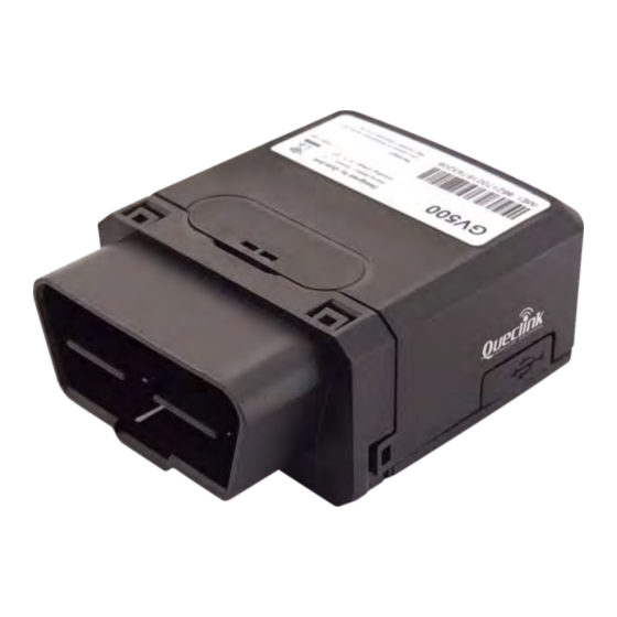
Table Inde .. 6 TABL LE 1: GV500 P PROTOCOL RE FERENCE .................... - Page 5 Figure In ndex .. 7 FIGU URE 1: APPEAR RANCE OF GV 500 ...................... 8 FIGU URE 2: THE OB BD II CONNECT TOR ON THE G GV500 .................. 1 FIGU URE 3: OPENIN NG THE CASE ........................ 2 FIGU URE 4: CLOSIN NG THE CASE ..
-
Page 6: R Revision Histor Ry
GV50 00 User Manua al ... -
Page 7: Referen Nce
GPS p position and m many other us seful function 1.1. . Referenc Tabl le 1: GV500 P Protocol Refe erence Documen nt name Rema GV500 @T Track Air Inte erface Protoc The ai... -
Page 8: Descrip Tion
OBD I II interface G GPS vehicle tr racking devic ce, compact d design and ea asy to insta all. GV500 co ontains an OB BD II connec ctor which co omplies with J1962 standa ard, a 10PIN conn... -
Page 9: Interfac Ce Definition
2.3. . Interface e Definitio GV500 has a an OBD II co onnector. It co ontains powe er supply and interfaces of... -
Page 10: G Getting Started D
GV5 500 User Manu 3. G Getting St tarted 3.1. . Opening g the Case Inse rt the triangu ular-pry-open er into the ga ap of the case e as shown b elow, push th he opener up until the c case unsnapp... - Page 11 GV5 500 User Manu Figure 3. Opening g the Case TRAC CGV500UM0 001 ...
-
Page 12: Closing The Case
GV5 500 User Manu 3.2. . Closing t the Case battery is glu ued to top co over, so befor re closing the e case you sh hould let the battery conn nector plug gged in. The s step of closin g case is show wn as followi... -
Page 13: Installin Ng A Sim Card D
GV5 500 User Manu 3.3. . Installing g a SIM Ca n the case an nd ensure the e unit is not powered. Sli ide the holde er right to op pen the SIM card. Inse rt the SIM c card into the holder as sh hown below... -
Page 14: Device S Status Led
S info. No external power and in nternal battery y voltage is lo ower OFF note 1) than 3.46V. G GV500 is pow wer off. No external l power and d internal ba attery voltag ge is Slow flashing below 3.55V... -
Page 15: Obd Ii P Parameters
GV5 500 User Manu 4. O OBD II-re elated fea atures 4.1. . Commun nication P rotocols 500 could mo onitor the OB BD II system v via not only communicati on protocols which define ed by E but also som me special pro otocols. - Page 16 OBD D II system. 2 - D Distance Stati istics: GV500 0 could get th he distance in two cases: d istance accum mulated since L is activated and distance accumulated...
- Page 17 RF Exposure Statement: For the product,under normal use condition is at least 20cm away from the b ody of the user,the user must keeping at least 20cm distance to the product. This device complies with Part 15 of the FCC Rules. Its operation is subject to the following two conditions: (1) This device may not cause harmful interference, and (2) This device must accept any interference received, including interference that may cause undesired operation. Note: THE GRANTEE IS NOT RESPONSIBLE FOR ANY CHANGES OR MODIFICATIONS NOT EXPRESSLY APPROVED BY THE PARTY RESPONSIBLE FOR COMPLIANCE. SUCH MODIFICATIONS COULD VOID THE USER’S AUTHORITY TO OPERATE THE EQUIPMENT This product has been tested and found to comply with the limits for Part 15 of the FCC Rules. These limits are designed to provide reasonable protection against harmful interference in a residential installation. This product generates, uses, and can radiate radio frequency energy and, if not installed and used in accordance with the instructions, may cause harmful interference to radio communications. However, there is no guarantee that interference will not occur in a particular installation. If this product does cause harmful interference to radio or television reception, which can be determined by turning the equipment off and on, the user is encouraged to try to correct the interference by one or more of the following measures: —Reorient or relocate the receiving antenna. —Increase the separation between the equipment and receiver. —Connect the equipment into an outlet on a circuit different from that to which the receiver is connected. —Consult the dealer or an experienced radio/TV technician for help. ...
Need help?
Do you have a question about the GV500 and is the answer not in the manual?
Questions and answers