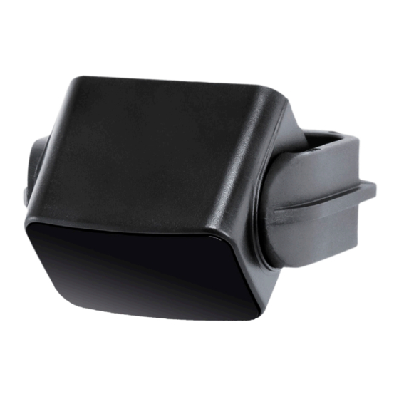
Cedes TLS 500 Installation And Operation Manual
Hide thumbs
Also See for TLS 500:
- Installation and operation manual (12 pages) ,
- Installation manual (2 pages)
Table of Contents
Advertisement
Quick Links
Installation and Operation Manual
FOLLOW THE INSTRUCTIONS GIVEN IN THIS MANUAL CAREFULLY. FAILURE TO DO
SO MAY CAUSE CUSTOMER COMPLAINTS AND SERIOUS CALLBACKS. KEEP
INSTRUCTION MANUAL ON SITE.
th
© CEDES Version 1.1 3
May 2011
... small, compact, versatile
IMPORTANT NOTE
CEDES
TLS 500
English
Part No. 110 605en
Advertisement
Table of Contents

Summary of Contents for Cedes TLS 500
- Page 1 … small, compact, versatile English IMPORTANT NOTE FOLLOW THE INSTRUCTIONS GIVEN IN THIS MANUAL CAREFULLY. FAILURE TO DO SO MAY CAUSE CUSTOMER COMPLAINTS AND SERIOUS CALLBACKS. KEEP INSTRUCTION MANUAL ON SITE. © CEDES Version 1.1 3 May 2011 Part No. 110 605en...
-
Page 2: Important Information
TLS 500 Installation and operation manual IMPORTANT INFORMATION THE TLS 500 SHOULD ONLY BE INSTALLED BY AUTHORIZED AND FULLY TRAINED PERSONNEL! ALL INSTRUCTIONS IN THIS MANUAL AND IN THE RELATED DOCUMENTS HAVE TO BE FOLLOWED AND FULLY COMPLIED WITH. IN ADDITION, THE INSTALLER IS REQUIRED TO COMPLY WITH ALL LOCAL LAWS AND STANDARDS. -
Page 3: Table Of Contents
1.1. Functionality After switching on the TLS 500, it calibrates a background measurement and saves this as a reference value. When an object enters the detection area, the reflection value changes. -
Page 4: Tls 500
Do not drill additional holes into the TLS 500. 2.3. Configuration (VR- and P-types only) There is a potentiometer at the back of the TLS 500. 1. Open the cover at the back of the TLS 500 carefully with a slotted screw driver. -
Page 5: Electrical Connection And Output Signals
A test cycle works as follows: The emitter is switched off and the output recognizes the change The TLS 500 has a red and a green LED to indicate and switches the output. its status which is dependent on the type. -
Page 6: Maintenance And Disposal
5.2. Disposal If there is no LED visible, please check the electrical connections. The TLS 500 should only be replaced if a similar device is installed. Disposal should be done using If the green LED is blinking (only N- or P-Type):... -
Page 7: Technical Data
TLS 500 Installation and operation manual 6. Technical data Optical Operating range 0.2 ... 6 m (VR-Type) Adjustable operating range Ø 0.24 m Active light spot @ 2 m ±3.5° Aperture angle 0.2 m Min. distance to background 10 s (N-Type) Recalibration time 3 ... -
Page 8: Ordering Information
System Part No. Device type Description 110 601 TLS 500-VR-NPN-LO TLS 500 with adjustable operating range 0.2 … 6 m 110 600 TLS 500-VR-PNP-LO TLS 500 with adjustable operating range 0.2 … 6 m 110 602 TLS 500-VR-PNP-DO TLS 500 with adjustable operating range 0.2 … 6 m... -
Page 9: Certificates
TLS 500 Installation and operation manual 8. Certificates 8.1. CE certificate © CEDES/May 2011 www.cedes.com... - Page 10 TLS 500 Installation and operation manual © CEDES/May 2011 www.cedes.com...
- Page 11 TLS 500 Installation and operation manual © CEDES/May 2011 www.cedes.com...
- Page 12 CEDES AG / Switzerland Tel. +41 81 307 2323 Fax +41 81 307 2325 info@cedes.com www.cedes.com CEDES AG is certified according to ISO 9001: 2008. CEDES AG reserves the right to modify or change technical data without prior notice.


Need help?
Do you have a question about the TLS 500 and is the answer not in the manual?
Questions and answers