Advertisement
Quick Links
DS7060 Control/Communicator
Armed
Status
Power
Fire
1
2
3
4
5
6
7
8
9
0
#
*
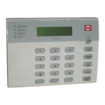
DS7447 KEYPAD
Normal Arming
Perimeter Arming, no entry delay
Perimeter Arming, with entry delay
Maximum Security Arming
Force Arming
Zone Bypass
Custom Arm
Quick Arm
Chime Mode
Zone Test
Read Alarm History
Battery Test
Communicator Test
Fire Reset
Fire Trouble
Remote Program Dial Out
Remote Program Answer
Local Battery/Sounder Test
Error Display
Error Display Reset
Clear Zone Bypass
Guest Code Enable
NOTE: Examples are shown in Commercial Mode, but are valid for any mode.
Reference Guide
for the
Armed
Status
Power
Fire
On
1
2
3
Off
4
5
6
Perimeter
Only
7
8
9
No
Entry
*
0
#
Bypass
System
Reset
DS7443 KEYPAD
Keypad Quick Reference Guide
Turning On (arming) your System
PIN + [On]
PIN + [No Entry] [Perimeter Only]
PIN + [Perimeter Only]
PIN + [No Entry] [On]
PIN + Arming Sequence + [Bypass]
PIN + [Bypass] followed by the Zone number
PIN + [#] + [4]
[#] + [On]
Turning Off (disarming) your System
PIN + [Off]
Commands for other System Features
PIN + [#] [7]
PIN + [#] [8] [1]
PIN + [#] [8] [9]
PIN + [System Reset]
PIN + [#] [8] [2]
PIN + [System Reset]
PIN + [Off] to silence, PIN + [System Reset] to clear
PIN + [#] [8] [3]
PIN + [#] [8] [6]
PIN + [#] [8] [5]
PIN + [#] [8] [7]
PIN + [System Reset]
PIN + [Bypass] [*] to clear
PIN + [#] [8] [4]
1
4
2
5
3
6
Armed
Perimeter
S tatus
Supervisory
Power
Bell Silenced
Fire
Trouble
On
Off
Perimeter
Only
No
Entry
Bypass
System
Reset
1 2 3 4 5 6 7 8
On
Off
1
2
3
Perimeter
4
5
6
Only
No
7
8
9
Entry
0
*
Bypass
#
System
Reset
DS7445 KEYPAD
Advertisement

Related Manuals for Bosch DS7060


Summary of Contents for Bosch DS7060
- Page 1 Reference Guide for the DS7060 Control/Communicator Armed Status Power Fire Armed Armed Perimeter S tatus Supervisory Status 1 2 3 4 5 6 7 8 Power Bell Silenced Power Fire Trouble Fire Perimeter Only Perimeter Perimeter Only Only Entry Entry...
-
Page 2: System Overview
• 6 zones (9 if Zone Doubling is used) 1.0 System Overview • Zone Response Time: All six zones can be The DS7060 Control/Communicator is a fully integrated programmed to respond at either 300 ±100 ms or a hard-wire security and residential fire alarm system. It can programmable time (common to all zones) that can be support up to 6 input zones and 15 individual users. -
Page 3: Enclosure Installation
CAUTION: The control is static sensitive. Make sure you touch earth ground before handling the The DS7060 control/communicator and the enclosure are control. This will discharge any static shipped together. The control, however, still needs to be electricity in your body. -
Page 4: Control Terminal Wiring
A complete functional test is required after any programming. CAUTION: Incorrect connections may result in damage to the unit. NOTE: Shared cable is not allowed for keypad, telephone, or siren wiring. Copyright © 2001 Detection Systems, Inc. Page 4 DS7060-AUS Reference Guide... -
Page 5: Operating Guide
A zone (1-6) is not ready to arm or if a (red) fire zone, a trouble condition exists. * = This light is present on the DS7445 only. ** = This light is present on the DS7443 and DS7445. Copyright © 2001 Detection Systems, Inc. DS7060-AUS Reference Guide Page 5... - Page 6 “No Entry” mode, but is disabled upon expiration of the exit delay. A zone is an input to the DS7060 Control Communicator. There are 6 hard-wired zones on the main circuit board. A delayed zone is ignored during the programmed times immediately following arming during the exit delay.
- Page 7 Fire Trouble restoral signals to be transmitted even though the panel may still be displaying these zone conditions. This is because the displays are latched until cleared by an operator action. Copyright © 2001 Detection Systems, Inc. DS7060-AUS Reference Guide Page 7...
- Page 8 Only programmable output 3 and the keypad shorted and the system is armed. It will generate a “Not sounders will pulse, regardless of the programming. Ready” (or “Fire Trouble” on fire zones) while unarmed Copyright © 2001 Detection Systems, Inc. Page 8 DS7060-AUS Reference Guide...
- Page 9 Fire zones always restore when the system is reset, regardless of this selection. Copyright © 2001 Detection Systems, Inc. DS7060-AUS Reference Guide Page 9...
- Page 10 Connect both relay commons to ground, and connect the N/O of each contact to terminal positions 23 and 26 (one to terminal 23, one to 26) of the DS7060. Connect one side of the relay coil to the selected Programmable Output and the other side of the coil to 12 volts Copyright ©...
- Page 11 Residential Mode only requires a PIN number for disarming and silencing alarms. • Quick Arm: If enabled, a PIN is not needed to arm. NOTE: Used only in conjunction with commercial mode. Copyright © 2001 Detection Systems, Inc. DS7060-AUS Reference Guide Page 11...
- Page 12 [7] twice for the letter “r” then press the right arrow key for the next letter. Enter: [6] for the letter “m”. Enter: [#] Program the next address, program a different address, or exit the Programmer’s Mode. Copyright © 2001 Detection Systems, Inc. Page 12 DS7060-AUS Reference Guide...
- Page 13 : Closing Reports ( and subsequent Opening Reports) are only sent when the system is fully armed. [PIN] + [ON] for Commercial Mode. [#] + [ON] for Residential Mode. Copyright © 2001 Detection Systems, Inc. DS7060-AUS Reference Guide Page 13...
- Page 14 • WDSRP Baud Rate: This selection determines the baud rate that the panel will use to Copyright © 2001 Detection Systems, Inc. Page 14 DS7060-AUS Reference Guide...
- Page 15 6.18 Address 24 - Keypad Report • Zone Alarm Restoral: This report is sent when the zone alarm is cleared. Refer to Address 07 for exact point at which report will be sent. Copyright © 2001 Detection Systems, Inc. DS7060-AUS Reference Guide Page 15...
- Page 16 Opening Report. Address 20 digit 1 (left most digit) • Zone Trouble Restoral: This report is sent when the must be set for 2 or 3 for these reports. zone trouble condition is cleared. Copyright © 2001 Detection Systems, Inc. Page 16 DS7060-AUS Reference Guide...
- Page 17 Remote Programming session, if an error occurs or session doesn’t terminate properly. • Local Programming Successful: This report is sent when local programmer’s mode is exited and no error is associated with the programming. Copyright © 2001 Detection Systems, Inc. DS7060-AUS Reference Guide Page 17...
- Page 18 • Comm. Failure Report: This report is sent after the programmed number of communicator attempts. Refer to Address 22 - Dial Attempts. Copyright © 2001 Detection Systems, Inc. Page 18 DS7060-AUS Reference Guide...
- Page 19 To delete the phone number from the display window, enter the *5 in all digits. 6.34 Address 46 - Programmer & Master Codes See the Users Guide for more information on Personal Identification Numbers. Copyright © 2001 Detection Systems, Inc. DS7060-AUS Reference Guide Page 19...
- Page 20 • Address 32 must be programmed to this report. 6.36 Address 48 - Automatic Test Report Interval NOTE: If AC power should restore before the “AC Failure Report” time, no AC Failure Report will be sent. Copyright © 2001 Detection Systems, Inc. Page 20 DS7060-AUS Reference Guide...
- Page 21 Address 31. 6.43 Address 57 - Expanded Zone Restorals Expanded Zone Restorals are used only if Zone Doubling (see Address 55) is selected. 6.41 Address 55 - Zone Doubling Copyright © 2001 Detection Systems, Inc. DS7060-AUS Reference Guide Page 21...
- Page 22 Custom Chime determines which zones will chime in the chime mode. Only Zones programmed as Perimeter Instant, Perimeter Delayed, Perimeter Homeguard or Perimeter Homeguard Follower in Address 01 can be chime zones. Copyright © 2001 Detection Systems, Inc. Page 22 DS7060-AUS Reference Guide...
- Page 23 User 14 User 15 DEVICE LOCATION TYPE Example Kitchen Invisible alarm, alarm on short, alarm on open, 24-hour Zone 1 Zone 1 Zone 1 Zone 1 Zone 1 Zone 1 Copyright © 2001 Detection Systems, Inc. DS7060-AUS Reference Guide Page 23...
- Page 24 Copyright © 2001 Detection Systems, Inc Detection Systems, Inc. 130 Perinton Parkway, Fairport, New York, USA 14450-9199 DS7060-AUS Reference Guide (585) 223-4060 • (888) 289-0096 • Fax: (585) 223-9810 P/N 36624E 9/01 Page 24 of 24...
Need help?
Do you have a question about the DS7060 and is the answer not in the manual?
Questions and answers