Sign In
Upload
Download
Table of Contents
Contents
Add to my manuals
Delete from my manuals
Share
URL of this page:
HTML Link:
Bookmark this page
Add
Manual will be automatically added to "My Manuals"
Print this page
×
Bookmark added
×
Added to my manuals
Manuals
Brands
Bosch Manuals
Cell Phone
CONETTIX B444-A2
Installation manual
Bosch CONETTIX B444-A2 Installation Manual
Cellular communicators
Hide thumbs
1
2
Table Of Contents
3
4
5
6
7
8
9
10
11
12
13
14
15
16
page
of
16
Go
/
16
Contents
Table of Contents
Bookmarks
Table of Contents
Table of Contents
Cellular Module Introduction
About Documentation
Bosch Security Systems B.V. Product Manufacturing Dates
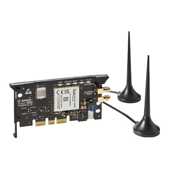
Component Overview
Installation
Install the Antenna
Install the Communicator
Remove the Communicator
Diagnostic LED Descriptions
Configuration
Activating the Cellular Communicator
Specifications
Advertisement
Quick Links
1
Installation
2
Diagnostic Led Descriptions
3
Configuration
Download this manual
CONETTIX Cellular Communicators
B444‑A2/B444‑V2
en
Installation manual
Table of
Contents
Previous
Page
Next
Page
1
2
3
4
5
Advertisement
Table of Contents
Need help?
Do you have a question about the CONETTIX B444-A2 and is the answer not in the manual?
Ask a question
Questions and answers
Related Manuals for Bosch CONETTIX B444-A2
Cell Phone Bosch B442 Installation Manual
Conettix plug-in gprs cellular (2 pages)
Cell Phone Bosch B465 Quick Start Manual
Conettix universal dual path communicator (2 pages)
Cell Phone Bosch B465 Quick Start Manual
Conettix universal dual path communictor (2 pages)
Cell Phone Bosch Conettix B465 Installation And Operation Manual
Universal dual path communicator (115 pages)
Cell Phone Bosch B441 Installation Manual
Conettix plug-in cdma cellular communicator (2 pages)
Cell Phone Bosch B430 Installation Manual
Plug-in telephone communicator (2 pages)
Cell Phone Bosch B440 Installation Manual
Conettix plug-in cellular communicator (2 pages)
Cell Phone Bosch B443 Installation Manual
Conettix plug-in hspa+ cellular communicator (2 pages)
Cell Phone Bosch CONETTIX B444-V2 Installation Manual
Cellular communicators (16 pages)
Cell Phone Bosch MM588 Operating Instructions Manual
(61 pages)
Cell Phone Bosch FPT-DACT Operations & Installation Manual
Fire communicator (60 pages)
Cell Phone Bosch radlonlcs D6412 Installation Manual
Control/communicator (76 pages)
Cell Phone Bosch DS7060 Reference Manual
Control/communicator (24 pages)
Cell Phone BOSCH GMS 509 DUAL User Manual
(22 pages)
Cell Phone Bosch GSM 509 User Manual
Bosch cell phone user guide (22 pages)
Cell Phone Bosch D9068 Operation And Installation Manual
Fire communicator (76 pages)
This manual is also suitable for:
Conettix b444-v2
F.01u.406.039
Table of Contents
Print
Rename the bookmark
Delete bookmark?
Delete from my manuals?
Login
Sign In
OR
Sign in with Facebook
Sign in with Google
Upload manual
Upload from disk
Upload from URL


Need help?
Do you have a question about the CONETTIX B444-A2 and is the answer not in the manual?
Questions and answers