Table of Contents
Advertisement
Quick Links
STATEMENT OF LIMITED WARRANTY
MÁQUINAS AGRÍCOLAS JACTO S.A. shall warrant the equipment described
in this manual and shall repair or replace parts and components which, under normal
operation and wear, in accordance with technical recommendations, show DEFECTS
IN MATERIAL OR WORKMANSHIP, based on the following conditions.
WARRANTY PERIOD
- 01 (one) year from the date of sale to the original purchaser.
WARRANTY APPLICATION
- JACTO shall honor this warranty, free of charge, if any part or component shows defect
in MATERIAL OR WORKMANSHIP, after final analysis at the factory.
THIS WARRANTY SHALL BE NULL & VOID IN CASE OF:
- Misuse of the equipment against specifications in the OPERATOR'S MANUAL, overwork
or accidents.
- Preventive/remedial maintenance performed by unauthorized people.
- Use of parts and components not supplied by JACTO.
- Modification of the equipment or any characteristic of the original design.
THIS WARRANTY SHALL EXCLUDE:
- Parts which show wear and tear due to use, UNLESS THEY SHOW DEFECTS IN
WORKMANSHIP, ASSEMBLY OR MATERIAL.
- Damages resulting from accidents.
- Transportation or freight of the equipment, parts and components in case such warranty
is not approved.
- Transportation and mobilization of technicians.
GENERAL INFORMATION:
- Parts replaced within the warranty period shall be property of JACTO.
- The warranty on replaced parts and components shall expire together with the equip-
ment warranty period.
- Eventual delays in performing services shall not give the owner right either to indemnity
or to extension of the warranty period.
- JACTO reserves the right to modify its products or to interrupt the manufacture without prior
notice.
19217 SW 119 th Ave.
Tualatin, Oregon 97062
Tel: (503) 885-8723
Fax: (800)511-3671
Toll free: (800) 522-8610
E-mail: info@jacto.com
Home page: www.jacto.com.br
JACTO INC.
10/2012- 1202909 - 0196-MI_USA
OPERATOR'S MANUAL
CD 400 / CD 500
1- INTRODUCTION
This manual contains information for the proper assembly, operation and care of
your sprayer.
Carefully read and follow the instructions contained in this manual before using your
sprayer.
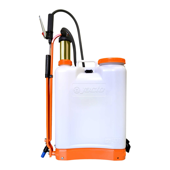
2- SPRAYER VIEW
Trigger valve
Chamber
Rod
Lever
Nozzle
3- SPECIFICATIONS
Model .............................. CD 400 / CD 500
Net weight (pounds) ....... 9.2 / 10.6
Tank
- Capacity (gallons) ......... 4.2 / 5.5
- Material ......................... Polyethylene (plastic)
- Filling opening diameter 4.5"
Hose
Lid
Diaphragm
Tank
Lance
Pump
- Type .................................. Piston
- Material ............................. Brass
- Max working pressure ...... 65 PSI
Lance length ....................... 19.5"
Hose length ........................ 53"
Nozzle installed ................. JD-12P
Advertisement
Table of Contents

Related Manuals for Jacto CD 400


Summary of Contents for Jacto CD 400
- Page 1 - 01 (one) year from the date of sale to the original purchaser. sprayer. WARRANTY APPLICATION - JACTO shall honor this warranty, free of charge, if any part or component shows defect 2- SPRAYER VIEW in MATERIAL OR WORKMANSHIP, after final analysis at the factory.
-
Page 2: Assembly Procedures
4- ASSEMBLY PROCEDURES Item Item Part no. Description Part no. Description Remove from the sprayer carton the following parts: 878033 Sprayer CD400 40 878132 Lid with diaphragm and 878157 Sprayer CD550 seal Tank 1198800 Washers and Locked ring 41 942193 Screw cap S-20 x 1.5 42 048116 Hose with dip tube 942680 Chamber cover 43 909192 Trigger valve handle... -
Page 3: Parts List
6- INSTALLING THE LEVER ON THE SHAFT AND THE ROD ON THE CHAMBER TOP PARTS LIST - Lightly grease the orifice on the pump lever. Fit Locked ring Washers a flat washer on the rod end. - Lightly grease the orifice on the chamber top. - Fit a flat washer on the shaft and rod. -
Page 4: Adjusting The Shoulder Strap
- Take the container cap off and carefully pour the rinse water into 10- ADJUSTING THE SHOULDER STRAP the spray tank. The tank is contoured for the operator comfort. - Continue holding the container over the spray tank opening The shoulder straps can be quickly adjusted to properly for approximately 30 seconds to the last drop. - Page 5 TRIPLE WASH OF EMPTY AGROCHEMICALS CONTAINERS - Remove the shaft (7) and detach the shoulder straps (8) from both sides. - Invert the positions as shown in the figure below (To install the shaft, follows ins- Even the containers considered empty contain chemical residues. tructions of the item 05).
-
Page 6: 15- Troubleshooting
14- CYLINDER MAINTENANCE - Do not eat, drink or smoke while spraying. - Do not pollute the environment. Chamber DISASSEMBLING - Remove the chamber from the cylinder. - Remove the nuts (1) from the cylinder. - Remove the cylinder (2). - Loosen the bolts (3), remove the spring (4), ball seat (5) and ball (6). -
Page 7: Safety Precautions
SAFETY PRECAUTIONS Wrench for maintenance of chamber and cylinder valve. (OPTIONAL). ATTENTION! READ CAREFULLY THE CHEMICALS MANUFACTURER'S LA- Part # : 452284 BELS CALIBRATION OF MANUAL KNAPSACK SPRAYER - Stir until it becomes an homogeneous - Put 1.5 gallons of water in a bucket and PROCEDURE mixture. -
Page 8: Spray Nozzles
SPRAY NOZZLES OPTIONAL ACCESSORIES FOR MANUAL KNAPSACK SPRAYERS IDENTIFICATION PRESSURE NOZZLE FLOW RATE APPLICATION TYPE (Part no. - Description) (psi) (gallons/min) Item Part no. Flat fan (1197535) JEF 110015 761882 Spray guard: prevents nonselective herbicides from drifting. 0.16 Green 902296 Boom 500: improves the coverage and increases the productivity.
Need help?
Do you have a question about the CD 400 and is the answer not in the manual?
Questions and answers