
Subscribe to Our Youtube Channel
Related Manuals for Edge-Core ECWO5110-L


Summary of Contents for Edge-Core ECWO5110-L
- Page 1 ECWO5110/ECWO5110-L 802.11a/b/g/n Outdoor Dual-Band Wireless Access I n s t a l l a t i o n G u i d e Point www.edge-core.com...
-
Page 2: Installation Guide
Installation Guide ECWO5110/ECWO5110-L Enterprise Access Point 802.11a/b/g/n Outdoor Dual-Band Wireless Access Point E072013-AP-R01 150200000760A... -
Page 3: How To Use This Guide
How to Use This Guide This guide includes detailed information on the Access Point (AP) hardware, including network ports, power, cabling requirements, as well as plug-in transceivers. This guide also provides general installation guidelines and recommended procedures. To deploy this AP effectively and ensure trouble-free operation, you should first read the relevant sections in this guide so that you are familiar with all its hardware components. - Page 4 How to Use This Guide ◆ Chapter 6 - AP Management — Connecting to the AP for management and information on the system status LEDs. ◆ Appendix A - Troubleshooting — Information for troubleshooting AP installation and operation. Related This guide focuses on AP hardware and installation, it does not cover software configuration of the AP.
-
Page 5: Table Of Contents
Contents How to Use This Guide Contents Figures Tables 1 Access Point Overview Hardware Description Key Hardware Components Key Technical Specifications 2 Installation Overview Package Contents System Configuration AP Installation Tasks 3 AP Chassis General Installation Guidelines Antenna Position Ethernet Cabling Radio Interference Weather Conditions How to Mount the Unit... - Page 6 Connection Procedure Grounding the Ethernet Cable 6 AP Management Understanding the System Status LEDs How to Connect to the Console Port How to Set an IP Address (ECWO5110-L) A Troubleshooting Diagnosing LED Indicators System Self-Diagnostic Test Failure Power Problems Installation...
-
Page 7: Figures
Figures Figure 1: ECWO5110/ECWO5110-L Outdoor Access Point Figure 2: Bottom Panel View Figure 3: Top Panel View Figure 4: Power Injector Module Figure 5: System Configuration Figure 6: Installing the AP on a Pole Figure 7: Making a Connection to the RJ-45 Port... -
Page 8: Tables
Tables Table 1: Key Technical Specifications Table 2: Power Injector Module Specifications Table 3: Power Injector Module Status LED Table 4: 10/100BASE-TX MDI and MDI-X Port Pinouts Table 5: 1000BASE-T MDI and MDI-X Port Pinouts Table 6: Console Cable Wiring Table 7: Troubleshooting Chart –... -
Page 9: Access Point Overview
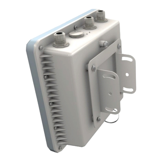
The ECWO5110/ECWO5110-L is a dual-band IEEE 802.a/b/g/n AP that is designed to deliver high-performance wireless services for clients or to provide bridge links between remote LANs. Housed in a weatherproof enclosure for mounting outdoors, the unit includes its own bracket for attaching to a pole, radio mast, or tower structure. -
Page 10: Key Hardware Components
Hardware Description Figure 1: ECWO5110/ECWO5110-L Outdoor Access Point Key Hardware The ECWO5110/ECWO5110-L consists of serveral key harware components. This Components manual describes each specific component, or related components, together with their installation requirements and procedures in each chapter. To understand each component in detail, refer to the relevant section. -
Page 11: Figure 3: Top Panel View
Chapter 1 | Access Point Overview Hardware Description Built-in 5 GHz Antenna The ECWO5110/ECWO5110-L includes an integrated 5 GHz antenna. For more information, see “How to Align Antennas” on page Console Port The port labeled “Console” provides an out-of-band serial connection to a terminal or a PC running terminal emulation software. -
Page 12: Figure 4: Power Injector Module
Pole/Wall Bracket Attachment Point External Antenna Connectors The ECWO5110/ECWO5110-L AP unit includes three external antenna connectors, two are for the 2.4 GHz radio and one for the 5 GHz radio (the unit also includes a built-in 5 GHz antenna). For more information, see “How to Connect External... -
Page 13: Key Technical Specifications
Chapter 1 | Access Point Overview Key Technical Specifications Key Technical Specifications The following table contains key system specifications for the AP. Table 1: Key Technical Specifications Item Specification Ports One 10/100/1000 Mbps RJ-45 port Network Interface RJ-45 Port: 1000BASE-T, PoE (PD) with waterproof cover Console Port RS-232, RJ-45 waterproof connector 2.4GHz Radio... -
Page 14: Installation Overview
Package Contents After unpacking the AP, check the contents to be sure you have received all the components. ◆ ECWO5110 or ECWO5110-L Outdoor Access Point ◆ Bracket Mounting Kit for pole mounting ◆ PoE Power Injector with power cord—either US, Continental Europe or UK ◆... -
Page 15: System Configuration
Chapter 2 | Installation Overview System Configuration System Configuration At each location where a unit is installed it must be connected to the local network, either by using the power injector module, or by a direct connection to an IEEE 802.3at-compliant LAN switch. The following figure illustrates the system component connections. -
Page 16: Figure 6: Installing The Ap On A Pole
Chapter 2 | Installation Overview AP Installation Tasks Go to the chapter “AP Chassis” Figure 6: Installing the AP on a Pole Attach one part of the bracket to the AP. Attach the other parts of the bracket to the pole. Link the two bracket parts together to secure the AP to the pole. -
Page 17: Figure 7: Making A Connection To The Rj-45 Port
Chapter 2 | Installation Overview AP Installation Tasks Figure 7: Making a Connection to the RJ-45 Port Connect outdoor-rated Category 5e or better cable to the RJ-45 port. Be sure to use the waterproof cover on the port. Task 4 Install the PoE Power Injector and Power On Install the PoE power injector indoors. -
Page 18: Figure 8: Connecting Ac Power
Chapter 2 | Installation Overview AP Installation Tasks Figure 8: Connecting AC Power Connect the AC power cord to a nearby AC power source. Connect Ethernet cable from the “DATA IN” port to a LAN switch. Connect straight-through Ethernet cable from the AP to the “DATA & POWER OUT” port. Task 5 Verify AP Operation Verify basic AP operation by checking the system LEDs. -
Page 19: Figure 10: Console Port
Chapter 2 | Installation Overview AP Installation Tasks Task 6 Make Initial Configuration Changes At this point you may need to make a few basic configuration changes to the AP so that it is compatible with your network. It is suggested to connect to the AP console port to perform this task. -
Page 20: Ap Chassis
AP Chassis The AP includes its own bracket kit for mounting the unit to a 1.5 to 6 inch diameter pole or part of a radio mast or tower structure. Before continuing with AP installation, first review the general guidelines and requirements in this chapter. -
Page 21: Ethernet Cabling
Chapter 3 | AP Chassis General Installation Guidelines ◆ Avoid placing the AP too close to any metallic surfaces, such as roof-installed air-conditioning equipment, tinted windows, wire fences, or water pipes. Ethernet Cabling From the intended AP location, plan a cable route from the unit outdoors to the power injector module indoors. -
Page 22: How To Mount The Unit
Chapter 3 | AP Chassis How to Mount the Unit this case, the snow or ice has to be cleared from the antennas to restore operation of the unit. How to Mount the Unit The AP can be mounted in the following ways using the included mounting bracket: ◆... -
Page 23: Figure 12: Attach Bracket To Ap
Chapter 3 | AP Chassis How to Mount the Unit Attach the square mounting plate to the AP with the supplied screws. Figure 12: Attach Bracket to AP Bracket Mount Points Supplied Bracket Mount Screws Square Mounting Bracket Part Attach the AP with its mounting plate to the bracket already fixed to the pole. Use the included long bolt to secure the AP to the pole bracket. -
Page 24: How To Connect External Antennas
Two antennas are required for 2.4 GHz operation and two can be used for 5 GHz operation. These antennas are not included in the AP package. The ECWO5110/ECWO5110-L unit includes an integrated high-gain antenna for 5 GHz operation. External antennas are not required for 5 GHz operation only for 2.4 GHz operation. -
Page 25: How To Align Antennas
How to Align Antennas When using the ECWO5110/ECWO5110-L unit with its 5 GHz integrated high-gain antenna, you will need to accurately align the antenna with another unit in the network to ensure optimum performance. Proper antenna alignment is particularly important for long-range point-to-point links. - Page 26 Chapter 3 | AP Chassis How to Align Antennas ◆ Point-to-Multipoint Configurations — In a point-to-multipoint configuration all APs must be aligned with a central AP that may be using external omnidirectional or sector antennas. The alignment process is the same as in point-to-point links.
-
Page 27: Power And Grounding
Power and Grounding This chapter focuses on how to power-on the AP. The AP can be powered using the included PoE Power Injector or by a direct connection to a PoE LAN switch. Connecting the AP to ground is also covered. This chapter includes these sections: ◆... -
Page 28: Table 2: Power Injector Module Specifications
Chapter 4 | Power and Grounding Power Injector Module Table 2: Power Injector Module Specifications Item Description AC Input 100~240 VAC, 50/60 Hz, 0.5 A DC Output 48 VDC, 0.35 A Output Power 16.8 W maximum DATA IN Port 10/100/1000BASE-T, RJ-45 socket DATA &... -
Page 29: How To Ground The Unit
Chapter 4 | Power and Grounding How to Ground the Unit How to Ground the Unit When connecting a ground wire to the AP, use the grounding screw on the unit. Be sure to use #14 AWG or larger copper core ground wire. Caution: Be sure that grounding is available and that it meets local and national electrical codes. -
Page 30: How To Install The Power Injector
Chapter 4 | Power and Grounding How to Install the Power Injector Note: Use cable strips to secure all cables to the pole. How to Install the Power Injector The power injector can be installed indoors on any horizontal surface, such as a desktop or shelf, or on a wall. - Page 31 Chapter 4 | Power and Grounding How to Install the Power Injector Insert the power cable plug into the standard AC socket on the power injector and the other end into a grounded, 3-pin socket, AC power source. Note: For International use, you may need to change the AC line cord. You must use a line cord set that has been approved for the socket type in your country.
-
Page 32: Network Connections
Network Connections This chapter focuses on making connections to the AP’s network interfaces and details on network cable specifications. The AP features one 1000BASE-T RJ-45 port as well as wireless interfaces. The sections that follow describe the network interfaces. This chapter includes these sections: ◆... -
Page 33: Understanding The Network Status Leds
Chapter 5 | Network Connections Understanding the Network Status LEDs Understanding the Network Status LEDs The AP includes LED indicators to indicate network link status and activity. The LEDs are shown below and are described in the following table. Figure 19: Network Status LEDs 5 GHz Link/Activity LED LAN Link/Activity LED 2.4 GHz Link/Activity LED... -
Page 34: How To Connect To The Rj-45 Port
Chapter 5 | Network Connections How to Connect to the RJ-45 Port How to Connect to the RJ-45 Port The connection between the AP’s RJ-45 port and the PoE power injector requires outdoor-rated Category 5E or better Ethernet cable with RJ-45 plugs on each end. The length of the Ethernet cable should be less than 100 meters (328 ft). -
Page 35: 1000Base-T Pin Assignments
Chapter 5 | Network Connections How to Connect to the RJ-45 Port Table 4: 10/100BASE-TX MDI and MDI-X Port Pinouts MDI-X Signal Name MDI Signal Name Transmit Data plus (TD+) Receive Data plus (RD+) -52V power (Negative V GND (Positive V port port Transmit Data minus (TD-) -
Page 36: Connection Procedure
Chapter 5 | Network Connections How to Connect to the RJ-45 Port Table 5: 1000BASE-T MDI and MDI-X Port Pinouts MDI Signal Name MDI-X Signal Name Bi-directional Pair A Plus (BI_DA+) Bi-directional Pair B Plus (BI_DB+) -52V power (Negative V GND (Positive V port port... -
Page 37: Figure 22: Waterproof Rj-45 Port Cover
Chapter 5 | Network Connections How to Connect to the RJ-45 Port Figure 22: Waterproof RJ-45 Port Cover Rubber RJ-45 Port Seal Outer Screw-on Cover Inner Plastic RJ-45 Plug Cover Screw-on Cable Clamp Inner Rubber Cable Seal Peal-off the adhesive backing on the rubber RJ-45 port seal and stick it on the end of the plastic RJ-45 plug cover. -
Page 38: Grounding The Ethernet Cable
Chapter 5 | Network Connections How to Connect to the RJ-45 Port Figure 23: Making a Connection to the RJ-45 Port RJ-45 Plug on Ethernet Cable Waterproof RJ-45 Port Cover Assembly Seal the PoE port connector using tar seal or weatherproof tape for extra protection against rain and moisture. -
Page 39: Figure 24: Outdoor-Rated Ethernet Cable Drain Wire
Chapter 5 | Network Connections How to Connect to the RJ-45 Port Figure 24: Outdoor-Rated Ethernet Cable Drain Wire Drain Wire Attach a grounding cable to the drain wire and then connect it to protective earth. Use weatherproof tape to cover and seal the attachment area on the Ethernet cable. -
Page 40: Ap Management
SNMP-based network management software. For a detailed description of the AP’s software features, refer to the ECWO5110 Management Guide. The ECWO5110-L supports network management from a EWS4502 wireless access controller through the Control and Provisioning of Wireless Access Points (CAPWAP) protocol. -
Page 41: Understanding The System Status Leds
Chapter 6 | AP Management Understanding the System Status LEDs Understanding the System Status LEDs The AP includes LED indicators that indicate system and port status. The LEDs are shown below and are described in the following table. Figure 25: System Status LEDs 5 GHz Link/Activity LED LAN Link/Activity LED 2.4 GHz Link/Activity LED... -
Page 42: How To Connect To The Console Port
Chapter 6 | AP Management How to Connect to the Console Port How to Connect to the Console Port The RJ-45 Console port on the AP is used to connect to the AP for out-of-band console configuration. The console device can be a PC or workstation running a VT- 100 terminal emulator, or a VT-100 terminal. -
Page 43: Figure 27: Console Port Connection
Chapter 6 | AP Management How to Connect to the Console Port Figure 27: Console Port Connection RJ-45 Console Port Console Cable Waterproof Port Cover Follow these steps to connect to the Console port: Unscrew the waterproof protective cap on the AP’s Console port. Attach the DB-9 end of the included serial cable to a DB-9 COM port connector on a management PC. -
Page 44: How To Set An Ip Address (Ecwo5110-L)
How to Set an IP Address (ECWO5110-L) How to Set an IP Address (ECWO5110-L) The ECWO5110-L requires management from a EWS4502 wireless access controller (AC), which can automatically discover the AP. If the network environment requires that you first configure a static IP address for the AP and AC, make a connection to the AP’s Console port and then follow these steps:... -
Page 45: A Troubleshooting
Troubleshooting Diagnosing LED Indicators Table 7: Troubleshooting Chart Symptom Action ◆ Power LED is Off Check connections between the PoE Power Injector, the power cord and the wall outlet. ◆ Contact your dealer for assistance. ◆ LAN LED is Off Verify that the AP and attached PoE Power Injector are powered ◆... -
Page 46: Installation
Chapter A | Troubleshooting Installation Installation Verify that all system components have been properly installed. If one or more components appear to be malfunctioning (such as the power cord or network cabling), test them in an alternate environment where you are sure that all the other components are functioning properly. -
Page 47: Out-Of-Band Access
Chapter A | Troubleshooting Out-of-Band Access Out-of-Band Access If you cannot access the on-board configuration program via a serial port connection: ◆ Be sure you have set the terminal emulator program to VT100 compatible, 8 data bits, 1 stop bit, no parity and 115200 Baud Rate. ◆... -
Page 48: Index
Index Numerics 10/100 pin assignments hardware errors 1000BASE-T pin assignments hardware overview hardware specifications humidity specifications AC power connection antenna position antennas, external in-band access indicators, LED injector module installation tasks basic installation tasks installation troubleshooting baud rate, console interference, radio bracket kit introduction cable grounding... - Page 49 Index package contents pin assignments console port RJ-45 port planning guidelines PoE injector module PoE port pole mount bracket pole mounting port cover, weatherproof port LEDs position of AP POST failure power injector power LED power problems product overview radio interfaces, connecting radio interference reset.AP RJ-45 connection...
- Page 51 Declaration of Conformity (DoC) can be obtained from www.edge-core.com -> support -> download -> declarations & certifications ECWO5110/ECWO5110-L E072013-AP-R01 150200000760A...
Need help?
Do you have a question about the ECWO5110-L and is the answer not in the manual?
Questions and answers