Webasto Air Top Evo 40 Installation & Operation Manual
Hide thumbs
Also See for Air Top Evo 40:
- Installation manual ,
- Service manual (63 pages) ,
- Workshop manual (59 pages)
Table of Contents
Advertisement
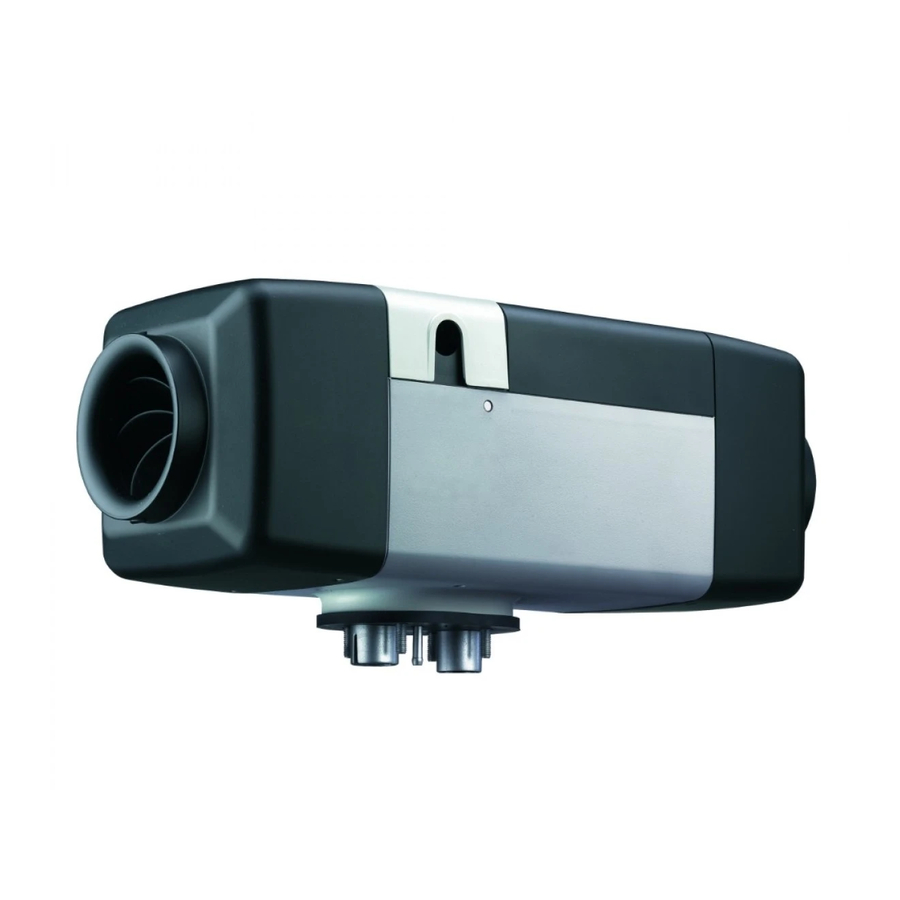
Air Heater
Air Top Evo 40 / 55
Installation/Operation Manual
WARNING!
– When heater is in use, the surface of the hot air outlet may become hot to the touch.
– Improper installation or repair of Webasto heating and cooling systems can cause fire
– Installation and repair of Webasto heating and cooling systems requires special
– NEVER attempt to install or repair a Webasto heating or cooling system unless you
– ALWAYS carefully follow Webasto installation and repair instructions and heed all
– Webasto rejects any liability for problems and damage caused by the system being
– Improper installation or installation by untrained personnel voids all warranties on
– Webasto heating and cooling systems require qualified and/or professional
Contact with skin may cause burns.
or the leakage of deadly carbon monoxide leading to serious injury or death.
Webasto training, technical information, special tools and special equipment.
have successfully completed the factory training course and have the technical skills,
technical information, tools and equipment required to properly complete the
necessary procedures.
WARNINGS.
installed by untrained personnel.
this product.
installation and repair technicians. Warranty shall be void if not installed by a
certified or trained installer/repair technician who has successfully completed the
factory training course for installation and repair of Webasto heating and cooling
systems, and has been provided with the technical information, tools and equipment
required to properly complete the necessary installation/repairs.
Advertisement
Table of Contents

Related Manuals for Webasto Air Top Evo 40


Summary of Contents for Webasto Air Top Evo 40
- Page 1 – Installation and repair of Webasto heating and cooling systems requires special Webasto training, technical information, special tools and special equipment. – NEVER attempt to install or repair a Webasto heating or cooling system unless you have successfully completed the factory training course and have the technical skills, technical information, tools and equipment required to properly complete the necessary procedures.
-
Page 3: Table Of Contents
4.2 Air Top EVO 40/55 Installation Situation ........ - Page 4 12.4 Fuel for Air Top EVO 40/55 D (Diesel/Heating Oil): .......
-
Page 5: Safety And General Information
General Information Webasto Product North America, Inc. is pleased to provide this installation manual with the Air Top EVO 40/55 air heater. When installed according to the guidelines stated in this manual, you can expect your customer to enjoy many years of trouble-free heater operation. -
Page 6: Regulation For Installation In The Vehicle
Failure to comply with all installation instructions is a misuse of Webasto products. The same applies for repairs without using genuine Webasto service parts. This will void the heaters “official Marks of Conformity.”... -
Page 7: Exhaust System
When the engine stops, the heating system must cut out automatically and the fuel supply must be stopped within 5 seconds. The heating system may remain in operation if a manual unit has already been activated. www.webasto.us Webasto Thermo & Comfort N.A., Inc. -
Page 8: Purpose Of The Air Heater
Purpose of the Air Heater Air Top Evo 40/55 Purpose of the Air Heater The Webasto Air Top EVO 40/55 air heaters are designed – to heat vehicle cabins, boats (Diesel Only), trucks, minibuses, vans and motor homes – to defrost vehicle windows –... -
Page 9: Installation
• 1/2 Heavy-Duty, low speed drill with good quality, sharp drill bits and a selection of hole saws. • Mounting/ Drilling Templates. Air Top EVO 40/55 Installation Situation NOTE: Check the installation situation of the relevant vehicle type. Installation Location The heater may be fitted both in the interior or on the exterior of the vehicle. -
Page 10: To Install The Heater
A seal (Figure 4) must be fitted between the heater and the vehicle body. This seal must be replaced each time the heater is installed. The support area for the heater foot must be flat. A special tool can be purchased from Webasto to drill the holes and, if necessary, smooth the support area. -
Page 11: Optional Mounting Plate
After installation, check that the heater casing is not in contact with any parts of the vehicle body. A failure to do this may result in the hot air fan binding internally (Figure 6). Ensure that all moving part can move freely Figure 6. Installation www.webasto.us Webasto Thermo & Comfort N.A., Inc. -
Page 12: Factory Plate / Label
(otherwise a duplicate model plate must be used). Inapplicable years must be erased from the model plate. Installation Example Figure 7. Installation example (installation conditions dependent on vehicle type) Webasto Thermo & Comfort N.A., Inc. www.techwebasto.com... -
Page 13: Cold And Hot Air System
The internal diameter of the main section of the hot air line should be: 90 mm (3.54 in.) minimum for the Air Top EVO 55 90 mm (3.54 in.) minimum for the Air Top EVO 40 NOTE: Only materials that can permanently withstand temperatures of at least 130°C (266°F) may be used for the hot air line. - Page 14 Installing heater in casing: - Provide a cross section area of at least 50 cm for the cold air inlet. - Seal off the hot air outlet such that no hot air can enter the casing. Webasto Thermo & Comfort N.A., Inc. www.techwebasto.com...
-
Page 15: External Temperature Sensor
– by close to heat sources (for example the vehicle’s own heating system). – be placed in direct sunlight (for example on the dashboard). – be installed behind curtains or the like. External temperature sensor Cover Figure 10. External temperature sensor - optional www.webasto.us Webasto Thermo & Comfort N.A., Inc. -
Page 16: Fuel Supply
This may cause problems during combustion. Vehicles with Fuel Injection Engines When installing the heater in a vehicle with fuel injection system, it is important to establish whether the fuel pump is located inside or outside the tank. Webasto Thermo & Comfort N.A., Inc. www.techwebasto.com... -
Page 17: Vehicles With Diesel Engines
(see Figure 13), in which case it must be ensured that the return line continues almost to the bottom of the tank (see Figure 12 for details of the minimum distance from the bottom of the tank). If this is not the case Webasto fuel extractors or standpipes (see Figures 12, 15 and 16) may be used. - Page 18 To Fuel Metering Pump Figure 13. Webasto fuel extractor Tank Connector Sealing ring Plastic tank Tank Fitting Sealing ring Figure 14. Fuel supply from plastic tank drain screw Figure 15. Fuel supply from plastic tank fitting Webasto Thermo & Comfort N.A., Inc. www.techwebasto.com...
-
Page 19: Fuel Metering Pump
The metering pump must be secured with a vibration-damping mounting. Its installation position is limited as shown in Figure 17 in order to ensure effective automatic bleeding. As a result of the risk of corrosion, only genuine Webasto parts may be used for the plug connections between the metering pump and the metering pump wiring harness. - Page 20 Fuel Supply Air Top Evo 40/55 0° - 90° Ø 5 Figure 18. Fuel filter Webasto Thermo & Comfort N.A., Inc. www.techwebasto.com...
-
Page 21: Combustion Air System And Exhaust System
Figure 20. Lines must not point in the direction of travel The lines must be located so that they cannot become clogged with dirt and road debris. Figure 21. Avoid the lines becoming clogged with dirt www.webasto.us Webasto Thermo & Comfort N.A., Inc. -
Page 22: Exhaust Muffler
If the exhaust pipe ends other than as shown in Figure 22, it will pose a fire risk. Exhaust Muffler Webasto recommends installing an exhaust silencer to reduce noise. The installation must satisfy the following requirements: - The installation location is as close as possible to the heater. -
Page 23: Electrical Connections
A weather sealed fuse holder is to be fitted to protect the heater (supplied with the heater harness). F = 20A (12V) F = 15A (24V) IMPORTANT! All power connections must be fused within 14” of the battery. Figure 25. Fuse holder - weather sealed www.webasto.us Webasto Thermo & Comfort N.A., Inc. -
Page 24: Control Element (Rheostat)
Air Top Evo 40/55 IMPORTANT! The Air Top EVO 40/55 requires 6.25 amps @ 12 volts or 12.5 amps @ 24 volts during start-up. The main power connection has to be made at a circuit designed to sustain this load without voltage drop. -
Page 25: Control Element (Smartemp)
– Apply any warning or caution stickers that are supplied with the SmarTemp Control. – Observe the installation / operating manual supplied for proper menu setup. Figure 30. Control element (SmarTemp) www.webasto.us Webasto Thermo & Comfort N.A., Inc. -
Page 26: Control Element (Mc04)
– Connect Control Panel to existing connectors on heater-unit wiring harness (see “Connection diagram/Circuit diagram”) – Pre-mount control unit in cut-out – Lightly press fastening screws into holes and screw in – Carefully clip on trim frame Webasto Thermo & Comfort N.A., Inc. www.techwebasto.com... - Page 27 – Observe information on adhesive labels and colored markings when connecting Control Panel to vehicle wiring harness Figure 33. Installing control element MC04 Figure 34. Connection diagram for Air Top EVO 40/55 with control element MC04 www.webasto.us Webasto Thermo & Comfort N.A., Inc.
-
Page 28: Pre-Start Checklist
Verify the correct fuses are in the specified locations per the installation manual. Ensure heater and vehicle fuse boxes are closed and secure. Was the Webasto fuse block installed in a location protected from water and / or moisture? Ensure battery is mounted securely and connections are properly tightened. - Page 29 Has user manual placed in glove box? Is the vehicle clock time correct after disconnecting the battery? If you have any questions, contact our technical support team at (800) 860-7866 or via email at: info-us@webasto.com. www.webasto.us Webasto Thermo & Comfort N.A., Inc.
-
Page 30: Operation Instructions
- Make sure the control unit cover is fitted in position. - Install contact guard if necessary. - Bleed the fuel supply system carefully using Webasto Thermo Test PC Diagnosis. - Switch on the heater via the control element (see control element operating instructions). -
Page 31: Product Registration
10.2.3 MC-04 Figure 37. Control element (MC-04) 10.3 Product Registration - Register the product on the internet under: http://techwebasto.com - Hand over the registration document to the next owner or user of the unit. www.webasto.us Webasto Thermo & Comfort N.A., Inc. -
Page 32: Troubleshooting
The heater continues to run in the same way as if it is switched off manually. After the heater stops the control unit will be set to fault lock-out. Overheating is indicated by the indicator flashing 10 times. Rectify the cause of the fault. Webasto Thermo & Comfort N.A., Inc. www.techwebasto.com... -
Page 33: Air Top Evo 40/55
If serious faults, such as overheating or no start, occur frequently, the heater will be set to fault lock-out (F 12) and can be restarted by disconnecting the supply voltage (e.g. removing the fuse). www.webasto.us Webasto Thermo & Comfort N.A., Inc. -
Page 34: Technical Data
Technical Data Air Top Evo 40/55 12. Technical Data 12.1 Heater Heater Air Top Evo 40 B Air Top Evo 40 D Air Top Evo 55 B Air Top Evo 55 D Type approval: EMC E1 03 5529 Type approval: Heating... -
Page 35: Electrical Components
If you change to low-temperature fuel, the heater must be operated for approx. 20 minutes so that the fuel system is filled with the new fuel. The Air Top EVO 40/55 heater is also licensed for use with PME (bio-diesel), which complies with DIN EN 14214. www.webasto.us... -
Page 36: Version
Version Air Top Evo 40/55 13. Version Air Top EVO 40/55 B (Gasoline) Air heater for gasoline (12 V) Air Top EVO 40/55 D (Diesel) Air heater for Diesel/heating oil (12 or 24 V) Webasto Thermo & Comfort N.A., Inc. -
Page 37: Annex
Air Top Evo 40/55 Annex 14. Annex 14.1 Drilling Template: heater Ø 7.5 Ø 29 Ø 28 Ø 7.5 Ø 7.5 Figure 39. Drilling Template for Heater Installation (Dimensions in millimeters) www.webasto.us Webasto Thermo & Comfort N.A., Inc. - Page 38 Annex Air Top Evo 40/55 Figure 40. Drilling Template for MC04 Control Panel Webasto Thermo & Comfort N.A., Inc. www.techwebasto.com...
-
Page 39: Legends To The Wiring Diagrams
Air Top Evo 40/55 Annex 14.2 Legends to the wiring diagrams Legend to wiring diagram Item Description Remarks Heater Air Top Evo 40 / 55 Control unit Control unit 1580 UniBox – Room temperature sensor Inside Overheat temperature sensor Overheating protection... - Page 40 Switch-on signal (ON/OFF) Multifunction (ventilation, boost, ECO) with control element MC02, only Boost activation for ambulance units Set-point sensor – CO2 setting Not used Set-point sensor + W-bus (Webasto Thermo Test PC-Diagnosis connection) Webasto Thermo & Comfort N.A., Inc. www.techwebasto.com...
-
Page 41: Wiring Diagrams
Air Top Evo 40/55 Annex 14.3 Wiring Diagrams Figure 41. Air Top Evo 40/55, 12V / 24V with rheostat www.webasto.us Webasto Thermo & Comfort N.A., Inc. - Page 42 Annex Air Top Evo 40/55 Figure 42. Air Top Evo 40/55, 12V/24V with MultiControl (MC04) control element Webasto Thermo & Comfort N.A., Inc. www.techwebasto.com...
- Page 43 Air Top Evo 40/55 Annex Figure 43. Air Top Evo 40/55, 12V/24V with SmarTemp www.webasto.us Webasto Thermo & Comfort N.A., Inc.
- Page 44 Webasto Thermo & Comfort N.A., Inc. 15083 North Road Fenton, MI 48430 Technical Assistance Hotline USA: (800) 555-4518 Canada: (800) 667-8900 www.webasto.us Org. 4/2015 Rev. N/A P/N: 5011187A www.techwebasto.com...
Need help?
Do you have a question about the Air Top Evo 40 and is the answer not in the manual?
Questions and answers