Webasto Air Top 2000 ST Installation Manual
Marine air heating systems for diesel powered marine vessels
Hide thumbs
Also See for Air Top 2000 ST:
- Workshop manual (70 pages) ,
- Installation instructions manual (60 pages) ,
- Installation manual (36 pages)
Table of Contents
Advertisement
Marine Air Heating Systems
Air Top 2000 ST
Air Top Evo 40
Air Top Evo 55
Installation Manual
For Diesel Powered Marine Vessels
WARNING!- CONCERNING INSTALLATIONS IN GASOLINE POWERED VESSELS!
Installation of a diesel fuel fired auxiliary heater in gasoline powered marine vessels
requires professional knowledge and strict adherence to safety information, special
installation instructions and restrictions. For these reasons, installation of a diesel fuel
fired auxiliary heater in gasoline powered marine vessels must be performed by an
authorized Webasto marine installation center. Installations must comply with all
applicable American Boat & Yacht Council recommendations and U.S. Coast Guard
regulations. Also, all relevant state and provincial licensing regulations if any, governing
the installation and use of auxiliary heating devices in watercraft must be observed.
To find an authorized Webasto marine installation center near you, please call (800) 860-7866 toll
free or visit our web site at: www.webasto.us
Advertisement
Table of Contents

Subscribe to Our Youtube Channel
Related Manuals for Webasto Air Top 2000 ST


Summary of Contents for Webasto Air Top 2000 ST
- Page 1 Also, all relevant state and provincial licensing regulations if any, governing the installation and use of auxiliary heating devices in watercraft must be observed. To find an authorized Webasto marine installation center near you, please call (800) 860-7866 toll free or visit our web site at: www.webasto.us...
- Page 2 – When heater is in use, the surface of the hot air outlet may become hot to the touch. Contact with skin may cause burns. – Improper installation or repair of Webasto heating and cooling systems can cause fire or the leakage of deadly carbon monoxide leading to serious injury or death.
-
Page 3: Table Of Contents
Air Top 2000 ST - Air Top Evo 40/55 Table of Contents Contents Page 1. Safety and General Information 1.1 Warning Symbols in this Installation Manual ............5 1.2 General Information . - Page 4 Table of Contents Air Top 2000 ST - Air Top Evo 40/55 12.Technical Data 12.1 Heater ................. . .34 12.2 Electrical Components .
-
Page 5: Safety And General Information
This manual represents our latest effort to produce the best technical documentation possible. In our efforts towards continuous, ongoing product improvement, we encourage our customers to write to us with their comments or criticisms concerning this manual and the Air Top 2000 ST, and Evo 40/55 air heating systems. - Page 6 The installation instructions within this manual are intended to be used as general installation guidelines only. For information concerning special marine applications or marine applications, contact an authorized Webasto marine dealer or Webasto Thermo & Comfort N. A., Inc. directly at: 1-800-860-7866 (USA) or 1- 800-667-8900 (Canada). ATTENTION It is the installer’s responsibility that the installation complies with all applicable American Boat &...
-
Page 7: Regulation For Installation In The Vessel
Air Top 2000 ST - Air Top Evo 40/55 Regulation for Installation in the Vessel Regulation for Installation in the Vessel Read this installation manual in its entirety before installing this equipment. In the following we would like to provide some useful advice and tips which, when followed, will ensure that the heating system fully meets your specific needs. - Page 8 Special Restrictions Concerning Gasoline Powered Vessels! WARNING! When installing a Webasto diesel fuel fired air heater in a gasoline powered boat, the heater MUST NOT be installed in the engine compartment. The Webasto heater must be installed above the top level of the engine compartment.
-
Page 9: Exhaust System
Air Top 2000 ST - Air Top Evo 40/55 Regulation for Installation in the Vessel • Fuel-carrying components must be protected against excessive heat and are to be installed so that any drippings or evaporating fuel can neither accumulate nor be ignited by hot components or electrical equipment. - Page 10 Regulation for Installation in the Vessel Air Top 2000 ST - Air Top Evo 40/55 2.10 Electrical System • Be sure to install an external temperature sensor if air heaters are operated in the fresh-air mode. 2.11 Automatic Control of the Heating System •...
- Page 11 Air Top 2000 ST - Air Top Evo 40/55 Mode of Operation Mode of Operation The air heater in the locker draws in outside air through the intake opening with an integrated fan. The air heated in the heater unit flows into the bow through connected warm air hoses. The warm air enters the cabins at the air outlets.
-
Page 12: Combustion Air Inlet
Installation Air Top 2000 ST - Air Top Evo 40/55 Installation IMPORTANT! The regulations governing installation on pages 7-10 must be adhered to. The heater must not be operated without the control unit cover (this will cause the heater to overheat) The installation instruction manual supplied with the heater must always be observed. -
Page 13: To Install The Heater
8. Cable outlet (either right or left) 5. Fuel Intake Figure 2. Dimensions of the Air Top 2000 ST Heater To Install the Heater The M6 nuts used to install the heater must be tightened with a torque of 6 Nm ±1 Nm (4.4 lb.-ft ± 74 lb.- ft). - Page 14 The support area for the heater foot must be flat. A special tool can be purchased from Webasto to drill the holes and, if necessary, smooth the support area. The seal can compensate for unevenness of max. 1 mm.
- Page 15 Figure 7. Universal Heater Mounting Bracket (Air Top EVO 40/55 and Air Top 2000 ST) ??? Place the heater on the mounting bracket. Ensure the rubber gasket on the base of the heater is in place.
-
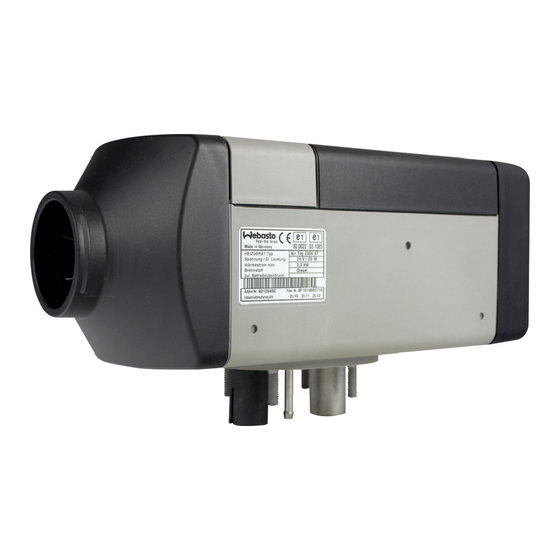
Page 16: Factory Plate / Label
Installation Air Top 2000 ST - Air Top Evo 40/55 Warning! There is a danger of drowning when drilling into the ship's outer skin! Drilling below the water line can cause the ship to sink! If the boat is in the water: check the drilling location! Have leak... -
Page 17: Installation Example
Air Top 2000 ST - Air Top Evo 40/55 Installation Installation Example 5 Air heater 8 Combustion air intake tube 6 Fuel Connection 9 Cool air inlet (return) 7 Exhaust gas tube 10 Heated air outlets Figure 9. Installation example (installation conditions dependent on vessel type) www.webasto.us... - Page 18 Webasto air heaters feature powerful blowers that are capable of conveying the heating air through long ducting runs for distribution throughout the vessel. Nevertheless, keep ducting runs and turns to a minimum.
- Page 19 Air Top 2000 ST - Air Top Evo 40/55 Heating Air Circuit Figure 10. Installation Diagram of an Air Heater with Fresh Air Mode of Operation Figure 11. Installation Diagram of an Air Heater with Recirculating Mode of Operation www.webasto.us...
-
Page 20: External Temperature Sensor
The return air for heating is drawn in from the cabin (and any side-rooms) either via flexible ducting or return openings. Use a Webasto fixed open grille to terminate the flexible duct. If the heater is mounted in a locker, use the grille supplied in the kit to ventilate the locker. - Page 21 Air Top 2000 ST - Air Top Evo 40/55 Heating Air Circuit Ducting Layouts - Typical 5 Ducting - 60mm (2.36”) ..P/N 50398497 1 Air Inlet Nozzle - 60mm (2.36”) P/N 1322405 6 Air Outlet Nozzle - 60mm (2.36”) . P/N 1322405 2 Ducting - 60mm (2.36”) .
- Page 22 Heating Air Circuit Air Top 2000 ST - Air Top Evo 40/55 Ducting Layouts - Continued 1 Air Inlet Nozzle... . P/N 91569 9 Air Outlet Nozzle ..P/N 91569 90mm (3.54”)
-
Page 23: Fuel Supply
Air Top 2000 ST - Air Top Evo 40/55 Fuel System Fuel System This heater installation must follow the American Boat & Yacht Council, Inc. (ABYC) guidelines. The Fuel system conforms to Inland Waterways specifications. Several specific regulations may apply including the use of flame resistant fuel pipe such as copper pipe, and fire resistant fixings. - Page 24 In the case of gasoline powered marine vessels, a separate fuel tank must be provided to supply Diesel fuel to the Webasto air heater. Gasoline fuel fired Webasto auxiliary heaters are not recommended nor certified for marine use and must never be installed in marine vessels.
-
Page 25: Fuel Metering Pump
Air Top 2000 ST - Air Top Evo 40/55 Fuel System The total length of fuel line run including the fuel pick-up tube to the inlet of the fuel pump must not exceed 2 meters (78 in.) and a suction height no greater than 1 meter (39 in.). - Page 26 Fuel System Air Top 2000 ST - Air Top Evo 40/55 Fuel System Parameters Maximum suction height (A) = 1 m (39 in.) Maximum suction length (A + B) = 2 m (78 in.) Maximum delivery length (C + D) = 6 m (234 in.) Maximum delivery height (D) = 3 m (117 in.)
- Page 27 Air Top 2000 ST - Air Top Evo 40/55 Exhaust System Exhaust System General Information Follow the diagrams below for correct installation guidelines and ensure the exhaust tube is routed with a minimum of bends, not to exceed 270 degrees in total and with a minimum bend radius of 50mm (2 in.).
-
Page 28: Exhaust Muffler
If exhaust gas lines are routed through rooms occupied by persons, these pipes must be replaced with genuine Webasto replacement parts after at least 10 years of service. At the lowermost point of the exhaust gas line, a condensation water drain (see Fig. 21, item 3) can be installed via which the condensation water collecting in the exhaust gas line can be drained off at regular intervals. - Page 29 Air Top 2000 ST - Air Top Evo 40/55 Exhaust System The maximum length of the combustion air intake tube is 5 meters (16.5 feet) without a silencer or 2 meters (6.5 feet) with a silencer. On no account are these lengths to be exceeded. The total radius of bends should not exceed 270 degrees with a minimum bend radius of 50mm (2 in.).
-
Page 30: Electrical Connections
Electrical Connections Air Top 2000 ST - Air Top Evo 40/55 Electrical Connections General Information Electrical connections are to be carried out in accordance with the circuit diagrams contained in this installation manual. Main power leads must have a minimum cross-sectional area of 4.0 mm (AWG 10 Gauge) and should be routed a short as possible. -
Page 31: Heater Connection
Air Top 2000 ST - Air Top Evo 40/55 Electrical Connections ATTENTION: Be sure not to touch the printed circuit board or conductors. Care should be taken to prevent discharge of static electricity that can damage sensitive circuitry. All the cables and wires that are not required must be insulated against accidental shorting or grounding. -
Page 32: Supply Voltage Connection
8.3.1 Fuse Specifications Air Top EVO 40/55: F = 20 A (12v); F = 15A (24V) Air Top 2000 ST: F = 15 A (12v); F = 10A (24V) Figure 26. Fuse holder - weather sealed IMPORTANT! All power connections must be fused within 14” of the battery. - Page 33 Air Top 2000 ST - Air Top Evo 40/55 Electrical Connections NOTE: The fibre optic lens must be in contact with the rotary knob. Figure 29. Installation of the control element - correct NOTE: The rotary knob must sit flush with the bezel (Figure 29) not above it as illustrated in Figure 30.
-
Page 34: Control Element (Smartemp)
Electrical Connections Air Top 2000 ST - Air Top Evo 40/55 Control Element (SmarTemp) The Control Panel should be installed in a suitable location on a flat surface if possible in a visible area. – Connect control panel to existing connectors on heater-unit wiring harness (see “Connections Diagrams Section”) -
Page 35: Control Element (Mc04)
Air Top 2000 ST - Air Top Evo 40/55 Electrical Connections Figure 34. Air Top 40/55 EVO with SmarTemp Control - connection diagram Control Element (MC04) The Control Panel should be installed in a suitable location (on a flat surface if possible) in a visible area. - Page 36 Electrical Connections Air Top 2000 ST - Air Top Evo 40/55 Figure 37. Connection diagram for Air Top EVO 40/55 with control element MC04 Webasto Thermo & Comfort N.A., Inc. www.techwebasto.com...
-
Page 37: Pre-Start Checklist
Verify the correct fuses are in the specified locations per the installation manual. Ensure heater and vessel fuse boxes are closed and secure. Was the Webasto fuse block installed in a location protected from water and / or moisture? Ensure battery is mounted securely and connections are properly tightened. - Page 38 Pre-Start Checklist Air Top 2000 ST - Air Top Evo 40/55 EXHAUST SYSTEMS Complete (Yes/No/Comments) Is the muffler and clamps securely tightened? Has muffler and exhaust tube been routed a safe distance (min. 4 in.) from flammable material? Ensure condensation drain-off is at the lowest area of exhaust tube.
-
Page 39: Starting Heater For The First Time
- Make sure the control unit cover is fitted in position. - Install contact guard if necessary. - Bleed the fuel supply system carefully using Webasto Thermo Test PC Diagnosis. - Switch on the heater via the control element (see control element operating instructions). -
Page 40: Product Registration
Starting Heater for the First Time Air Top 2000 ST - Air Top Evo 40/55 10.1.3 MC-04 Figure 40. Control element (MC-04) 10.2 Product Registration - Register the product on the internet under: http://techwebasto.com - Hand over the registration document to the next owner or user of the unit. -
Page 41: Troubleshooting
Air Top 2000 ST - Air Top Evo 40/55 Troubleshooting 11. Troubleshooting 11.1 Error code output - If an error occurs, the unit outputs a fault code via the control element. - You will find further information in the operating instructions and in the heater workshop manual. - Page 42 Troubleshooting Air Top 2000 ST - Air Top Evo 40/55 The heater is shut down (fault lock-out) if: – No or incorrect start – Temperature sensor defective – Overheating sensor interrupt or short circuit – Overheating sensor installed incorrectly – Ceramic glow pin interrupt or short circuit –...
-
Page 43: Technical Data
Air Top 2000 ST - Air Top Evo 40/55 Technical Data 12. Technical Data 12.1 Heater Heater Air Top 40 D Air Top Evo 55 D Air Top 2000ST e1*72/245*95/ Type approval: EMC E1 03 5529 E1 03 5529 54*1085*00... -
Page 44: Electrical Components
Technical Data Air Top 2000 ST - Air Top Evo 40/55 The technical data apply under the following conditions: °C - Ambient temperature: +20 - Geodetic height: 0 m above sea level - Rated voltage The standard tolerances of ±10 % for heaters shall apply if no limits are specified The values in brackets apply for the extended heating capacity (boost function) that is activated temporarily during each start. -
Page 45: Wiring Diagrams
Air Top 2000 ST - Air Top Evo 40/55 Wiring Diagrams 13. Wiring Diagrams 13.1 Legend to Air Top EVO 40/55 Wiring Diagrams Item Description Remarks Heater Air Top EVO 40 / 55 Control unit 1580 Control unit Control unit 1574 UniBox –... -
Page 46: Version
Wiring Diagrams Air Top 2000 ST - Air Top Evo 40/55 Legend to remarks in Air Top EVO 40/55 wiring diagrams Item Remarks Positive from terminal 15/75 to connection 10: Continuous heating mode is possible in connection with quick heating function provided the ignition is switched on. - Page 47 Air Top 2000 ST - Air Top Evo 40/55 Wiring Diagrams 13.2 Wiring Diagrams for Air Top EVO 40/55 Figure 42. Air Top 40/55, 12V / 24V with rheostat www.webasto.us Webasto Thermo & Comfort N.A., Inc.
- Page 48 Wiring Diagrams Air Top 2000 ST - Air Top Evo 40/55 Figure 43. Air Top 40/55, 12V/24V with MultiControl (MC04) control element Webasto Thermo & Comfort N.A., Inc. www.techwebasto.com...
- Page 49 Air Top 2000 ST - Air Top Evo 40/55 Wiring Diagrams Figure 44. Air Top 40/55, 12V/24V with SmarTemp www.webasto.us Webasto Thermo & Comfort N.A., Inc.
- Page 50 Wiring Diagrams Air Top 2000 ST - Air Top Evo 40/55 13.3 Legend to Air Top 2000 ST Wiring Diagram with Control Element (SmarTemp) Diagnostic K cable W bus (SmarTemp uses a mini USB Connector) adjustment (see workshop manual) ...
- Page 51 Air Top 2000 ST - Air Top Evo 40/55 Wiring Diagrams 13.4 Wiring Diagrams for Air Top 2000 ST Figure 45. Air Top 2000 ST, 12 / 24 Volt with SmarTemp control element www.webasto.us Webasto Thermo & Comfort N.A., Inc.
- Page 52 Wiring Diagrams Air Top 2000 ST - Air Top Evo 40/55 Figure 46. Air Top 2000 ST,12 and 24 Volt with Control Element (Rheostat) Control Unit Connector 8-Pin (Main Harness) Flame Sensor Connector 2-Pin (Fuel Pump) Air Temperature Sensor Connector 2-Pin (Fuel Pump) Temperature Limiter Connector 2-Pin (Temp.
- Page 53 WEBASTO AT 2000ST & 40/55 EVO Diesel Marine LIMITED WARRANTY Webasto Thermo & Comfort North America, Inc. (herein after referred to as Webasto) warrants Marine heaters and heater kits against defects in material and workmanship for two (2) years or 2000 operating hours, whichever comes first, effective at the time of installation or vehicle registration date for Original Equipment installations (OE).
- Page 54 Webasto Thermo & Comfort N.A., Inc. 15083 North Road Fenton, MI 48430 Technical Assistance Hotline USA: (800) 555-4518 Canada: (800) 667-8900 www.webasto.us Org. 4/2015 Rev. 8/2018 P/N: 5011424B www.techwebasto.com...
Need help?
Do you have a question about the Air Top 2000 ST and is the answer not in the manual?
Questions and answers