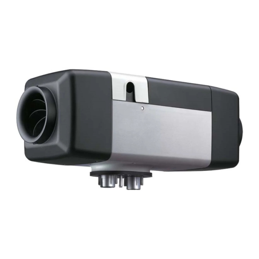
Webasto Air Top Evo 40 Manual
- Service manual (63 pages) ,
- Workshop manual (59 pages) ,
- Installation & operation manual (44 pages)
Advertisement
Use of symbols and highlighting

This signal word denotes a hazard with a high degree of risk which, if not avoided, may lead to death or serious injury.

This signal word denotes a hazard with a moderate degree of risk which, if not avoided, may lead to minor or moderate injury.

This signal word denotes a hazard with a low degree of risk which, if not avoided, may lead to minor or moderate injury.
NOTE
This symbol denotes a special technical feature, or (if not observed) potential damage to the product.
![]() This symbol refers to separate documents which may be enclosed or can be requested from Webasto.
This symbol refers to separate documents which may be enclosed or can be requested from Webasto.
Safety
Intended use
The heater is used exclusively for comfort purposes. Due to its installation, it must not become a safety-relevant component for proper functioning of the vehicle.
NOTE
The heater is not approved for the purpose of directly heating the cargo area of ADR vehicles (hazardous substance transportation).
The heater works independently of the vehicle engine and is integrated in the electrical system of the vehicle.
The heater is approved for the following applications:
- Car, light truck (LCV)
- Trucks, buses in EU vehicle classes M, N and O.
- Caravans, motor homes, boats, pleasure craft
- Earth-moving machinery
- Construction machines
- Vehicles that can be used in commercial, light-industrial and industrial environments
- Agriculture and forestry machines
General safety information
Safety information on operation
Risk of injury from the defective unit
Do not operate a defective Air Top Evo 40 | 55 and put it out of service by removing the fuse:
- prolonged heavy smoke development
- unusual burner noise
- smell of fuel
- permanent fault switch-offs with error messages (flash code)
- damaged heater.
- Contact a Webasto service workshop.
Risk of burn injuries due to insufficient distance between hot air outlet and persons
Burn injuries
- Make sure that persons are protected from the direct hot air flow from the heater and from contact with surfaces that will become hot.
- Heat-sensitive parts must be protected from the direct hot air flow.
Danger of explosion
In environments with combustible vapours, flammable dust and hazardous goods (e.g., petrol stations, tank facilities, fuel store, coal bunkers, timber yard or grain warehouses).
- Do not switch on or operate the heater.
Risk of explosion from explosive and flammable hazardous goods
For hazardous material vehicles, restriction of the heater operation (ADR) is required to prevent severe burns.
- Do not operate the heater at hazardous material loading points.
- Do not operate the heater when loading and unloading hazardous materials.
Danger of poisoning and suffocation
Do not operate the heater in closed rooms that do not have an exhaust extraction unit.
- Do not switch on or operate the heater, also not with programmed heating start.
Danger of fire
Flammable materials or liquids in the hot air flow.
- Keep the hot air flow free.
NOTE
Do not operate heater without control unit cover in place.
Safety information on installation
Danger of lacerations due to sharp edges
- Fit protectors on sharp edges.
Live parts are dangerous
- Disconnect the vehicle from the voltage supply before installation.
- Make sure the electrical system is earthed correctly.
- Always comply with all legal requirements.
- Observe the information on the type label.
Avoiding damage to property
NOTE
Protect the Air Top Evo 40 | 55 against mechanical stress:
- e.g. dropping, impacts or knocks.
- Do not place any objects on top of the heater.
- Do not stand on the heater.
NOTE
The fan of the heater keeps running for approx. 240 seconds after switching off via the control element (40 s for ADR). Switching off incorrectly, without afterrun, can cause damage to the Air Top Evo 40 | 55.
- Always switch off the Air Top Evo 40 | 55 via the control element.
Regulations and legal requirements
The Air Top Evo 40 | 55 heater has been type-tested and approved in accordance with ECE-R 10 (EMC) and ECE-R 122 (heater).
Application of combustion heaters in hazardous material vehicles (ADR)
The requirements stipulated in Regulation ECE R122, Annex 9 – Combustion Heaters – must additionally be observed when installing the Air Top Evo 40 | 55 in hazardous material vehicles. The relevant measures are specified in this document.
Vehicles used for the purpose of transporting dangerous goods are type approval tested in accordance with ECE-R 105. The following measures are derived for our combustion heaters.
- The electrical cable/wiring harness must be sufficiently dimensioned to prevent overheating. The electrical cable/wiring harness must be sufficiently insulated. All electrical circuits must be protected by fuses or automatic circuit breakers. The cables must be installed and firmly secured such that the wirings are adequately protected against mechanical and thermal stress.
- The combustion heaters must be type-tested in accordance with ECE-R 122 and comply with Annex 9 - Additional regulations for vehicles used for transporting hazardous substances.
- The combustion heaters and their exhaust gas piping system must be designed, arranged, protected or covered so as to prevent any unacceptable risk of heating or ignition of the load.
- In the event of any fuel line leakage, the fuel shall drain to the ground without coming into contact with hot parts of the vehicle or the load.
- The exhaust system as well as the exhaust pipes shall be so directed or protected to avoid any danger to the load through heating or ignition. Parts of the exhaust system situated directly below the fuel tank shall have a clearance of 100 mm or be protected by a thermal shield.
- It must only be possible to switch the combustion heater on manually. Programming devices shall be prohibited. The combustion heater may be switched back on manually after switching off the vehicle engine.
Requirements relating to the basic unit:
When switched off, it is permissible for combustion heaters to continue running for max. 40 seconds. Only combustion heaters are to be used with heat exchangers that are not damaged during their standard operating period by the reduced afterrunning time of 40 seconds.
Installing Heater
Installation location requirements
Danger of overheating
Outcome: Risk of fire. Protect vehicle components in the vicinity of the heater, hot air outlet and exhaust line from overheating by implementing the following measures:
- Maintain minimum safety distances.
- Ensure adequate ventilation.
- Use fire-resistant materials or heat shields.
- Always comply with legal requirements.
- When installing a heater in hazardous material vehicles: comply with ADR guidelines.
The installation location must satisfy the following requirements:
- There is sufficient space for the unit (see chapter "Dimensions and space requirements").
- The installation location is protected from mechanical damage.
- The installation location is protected from splash water and water spray wherever possible.
- The installation location is above the maximum permissible fording level of the vehicle.
- The combustion air inlet and exhaust gas outlet are separate (see chapter "Combustion air system" and chapter "Exhaust system").
- The connections for the combustion air system and the exhaust system are completely on the outside.
- Persons cannot come in contact with hot surfaces. Install contact guard if necessary.
- Heat-sensitive parts are protected from high temperatures. Install heat shield if necessary.
Installation example

- Control element
- Heater
- Fuse
- Tank extracting device
- Fuel filter (accessory)
- Fuel pump
- Exhaust silencer (accessory)
- Combustion air intake line
- Combustion air intake silencer (accessory)
- Maximum permissible fording level
Dimensions and space requirements

- Hot air outlet
- Cold air inlet
- Cable outlet (optionally on right or left)
- Combustion air inlet
- Fuel inlet
- Exhaust gas outlet
- Recommended space requirements for hot air outlet (without air duct)
- Space requirements for cold air inlet
- Space requirements for installing heater
- Heater is supported only by the base
Permissible installation position
Danger of poisoning and suffocation due to exhaust fumes
Make sure that:
- the casing rests only on the base after installation.
- the base seal is fitted correctly.
- Exhaust gasses are routed only to the outside.
- Ensure the correct installation position.

- Petrol
- Diesel
- Drill holes with the aid of the drilling template. See Fig. 4 and Fig. 29.

Base seal

- Fit base seal between heater and support surface.
NOTE
Unevenness >1 mm: Flatten out support surface. - Secure heater at base with M6 (6 Nm) nuts.
- Make sure that the heater rests only on the base.
Type label
Except for the year of installation, remove all the year numerals on the type label and type label duplicate.

If the type label (Fig. 5) is not visible after installing the heater:
- Secure the type label duplicate such that it is clearly visible in a protected area on the vehicle.
Cold and hot air system
Information on cold and hot air system
NOTE
The maximum pressure loss in the hot air system must not exceed 2 hPa (Air Top Evo 40) or 3 hPA (Air Top Evo 55) (see chapter "Technical data"). The heating capacity will be reduced if the limits are exceeded.
- Do not connect the cold and hot air system of the heater to the externally controlled air routing systems (e.g. vehicle air conditioning system).
Recirculated air mode and fresh air mode
The cold air can be drawn in from the outside (fresh air mode) or inside (recirculated air mode).
Temperature control
There are two options for temperature control. One of the two options is specified automatically.
Options:
- The heater regulates the heating capacity depending on the temperature of the cold air intake and the temperature set on the control element.
- The heater regulates the heating capacity depending on the temperature of an external room temperature sensor and the setpoint temperature set on the control element. See chapter "External room temperature sensor (optional)".
Installation location requirements (cold air)

The installation location for the cold air inlet must satisfy following requirements:
- Hot air is not drawn in from the vehicle's heating system.
- Hot air is not drawn in from the heater.
- Exhaust gas is not drawn in.
- The installation location is protected from splash water and water spray.
- The installation location is above the maximum permissible fording level of the vehicle.
Installation location requirements (hot air)
Risk of burn injuries due to insufficient distance between hot air outlet and persons
Burn injuries
- Make sure that persons are protected from the direct hot air flow from the heater and from contact with surfaces that will become hot.
- Heat-sensitive parts must be protected from the direct hot air flow.
Cold and hot air ducts
Requirements for the cold and hot air ducts
| Requirements for the cold and hot air ducts | Value | |
| Thermal endurance | > 130°C* | |
| Recommended inside diameter of main hot air duct | Air Top Evo 40 | 55 | 90 mm |
* (short-term > 150°C)
- Install cold and hot air ducts with minimal resistance to flow.
Installing cold and hot air ducts
Risk of injury by rotating fan wheel
Lacerations. If no cold air duct is used: Install mesh guard over intake.
- Make sure that the installation location satisfies the requirements.
- Make sure that the hot air duct satisfies the requirements.
- Make sure the cold air inlet, hot air outlet as well as the cold and hot air ducting are installed in the correct position.
- Drill holes.
- Secure cold and hot air ducts at all connections.
Installation without cold air duct (cold air)

- Install the mesh guard on the cold air inlet side.
Installing heater in casing
- Provide a cross section area of at least 50 cm2 for the cold air inlet.
- Seal off the hot air outlet such that no hot air can enter the casing.
External room temperature sensor (optional)
Installation location requirements for the external room temperature sensor
The installation location must satisfy the following requirements:
- The installation location is at mid-level of the area to be heated.
- The installation location is outside the hot air flow.
- The installation location is outside the range of other heat sources (e.g. vehicle heating system).
- The installation location is not in direct sunlight (e.g. not on the dashboard).
- The air can circulate unhindered (e.g. not covered by curtains).
Fuel supply
NOTE
Preferably, install the heater and fuel pump components at the same height as the fuel tank. Failing that, pay attention to the figures and the tables.
The fuel can be taken off at the following points:
- Fuel supply or return pipe on vehicle engine
- Vehicle fuel tank
- Separate fuel tank
The fuel line consists of an intake and pressure side:
- Intake side: Connection of fuel tank to fuel pump
- Pressure side: Connection of fuel pump to heater
Permissible pressure at the fuel take-off point

| Requirements for the fuel lines | Value | ||
| Inside diameter | 2 mm | ||
| L1 | Length (intake side) | max. 5m | |
| L2 | Length (pressure side) | max. 10m | |
| L1 + L2 | Overall length | max. 12m | |
| H1 | Height difference from heater – fuel pump (heater above fuel pump) | max. 3m | |
| H2 | Height difference from heater – fuel pump (heater below fuel pump) | max. 1m | |
| h1 [m] | pmax [bar] | ||
| h1 = 0 | -0.1 to +0.5 | ||
| h1 = 0 to 1 | -0.1 to +0.4 | ||
| h1 = 1 to 2 | -0.1 to +0.3 | ||
| h2 [m] | pmax [bar] | ||
| h2 = 0 to 1.3 | -0.1 to +0.5 | ||
| Fuel pressure correction at height difference between tank and fuel pump [m] | pmax [bar] | ||
| h1 = 0 | -0.1 to +0.5 | ||
| h1 = 0 to 1 | -0.1 to +0.4 | ||
| h1 = 1 to 2 | -0.1 to +0.3 | ||
| h2 = 0 to 1.3 | -0.1 to +0.5 | ||
Removing fuel from vehicle's fuel supply and return line
Installing fuel extractor

- from fuel tank
- to fuel pump
- to motor
- The pressure at the fuel take-off point is in the permissible range (see Fig. 8 and tables).
- Install only original Webasto fuel extractors.
- When taking off fuel at the return line:
- Make sure that the installation location satisfies the re-quirements.
- Make sure that the return pipe is not closed off by anon-return valve.
- Make sure that the return pipe extends to the base of the fuel tank.
- When taking off fuel from the swirl pot:
- Make sure that the swirl pot is not completely emptied.
Taking off fuel from the vehicle tank
Risk of fire by fuel escaping from leaking fuel tank
Skin burns.
- Do not drill into a plastic fuel tank.
- When retrofitting the fuel take-off system on a plastic tank: Install suitable tank extracting device only on the vehicle's fuel delivery unit.
Installing tank extracting device on vehicle fuel delivery unit

- Webasto tank extracting device
- Section of vehicle's fuel delivery unit with hole
- Standpipe of Webasto fuel extractor
- Minimum distance of 10 mm between the standpipe and the base of the fuel tank
- Make sure that the standpipe of the Webasto tank extracting device cannot impair operation of the vehicle's fuel delivery unit with fuel gauge in any operating mode.
- Make sure that the mounting surface for the Webasto tank extracting device is clean, level and free of burrs.
- In the installed position, maintain a minimum distance of 10 mm between the standpipe and the base of the fuel tank. Maintain a minimum distance of 20 mm above the base of the fuel delivery unit.
- Observe the safety measures specified by the vehicle manufacturer.
- Observe the tightening torque requirements specified by the vehicle manufacturer.
Taking off fuel from a separate fuel tank
- Do not install the fuel filler neck in the vehicle interior.
- Only use a fuel tank that can be closed off with a filler cap.
- Clearly mark the type of fuel to be used on the fuel filler neck.
Fuel line
Fuel line requirements
NOTE
Use only steel or plastic fuel lines made from light and temperature-resistant P A12/ETFE, PA12/ EFEP, PA9T/ PA12 in accordance with DIN 73378.
- Make sure that the connections are tight.
Connecting fuel lines

- Hose clip
- Fuel line
- Hose
- VDA connector
- Make sure that the connections are tight.
Install fuel line
NOTE
Malfunctions during combustion caused by gas bubbles and high fuel temperatures. Gas bubbles caused by the heat from the engine and high fuel temperatures can cause malfunctions during operation.
- Install the fuel lines in cool areas.
NOTE
Use the Webasto Thermo Test to fill the fuel lines before starting the heater.
- Keep line lengths as short as possible.
- Avoid sagging of the fuel line.
- Fasten fuel lines.
- Protect the fuel lines from damage:
- Install stone impact guard.
- Fit protectors on sharp edges.
- Protect fuel lines from high temperatures (e.g. from exhaust pipe):
- Install heat shield if necessary.
- Do not install fuel lines in areas where heat builds up.
- Make sure the fuel lines are not damaged.
Fuel pump
NOTE
Damage to the fuel pump.
- Lines should be filled under the control of the Webasto Thermo Test PC Diagnostics only.
- Do not operate the fuel pump using the vehicle voltage.
NOTE
Operating the heater with any other than the DP 42.4 fuel pump will invalidate the warranty and type approval.
- The heater must only be operated using the fuel pump DP 42.4.
Installation location requirements:

The installation location must satisfy the following requirements:
- The installation location is close to the fuel tank in order to keep the intake fuel line as short as possible.
- The installation location is protected from stone impact.
- The installation location is protected from high temperatures.
Installing fuel pump
NOTE
A heat shield can be installed to protect against shortterm overheating and radiated heat.
- Ensure the correct installation position.
- Pay attention to the direction of flow of the fuel. The end with the connector is always the outlet end.
- Secure the fuel pump to the vehicle using a vibration-damping mount (e.g. rubberised Webasto clip).
- Connect the fuel pump and the wiring harness.
Fuel filter
NOTE
- If use of poor-quality fuel is likely, a Webasto fuel filter must be installed.
- Enter fuel filter in the vehicle's service booklet.
Installation position of fuel filter
NOTE
Webasto recommends installing the fuel filter in a vertical position. Vertical installation improves bleeding of the fuel filter.
Fuel filter installation
- Ensure the correct installation position. Pay attention to the direction of flow of the fuel (arrow) in Fig. 13.


Fuel supply sticker
- Affix the sticker "Switch Off Heater Before Refuelling" (included in scope of delivery) in area of fuel filler neck.
![]()

Combustion air system
Notes on combustion air system
Unconsciousness and risk of suffocation
Possible lack of oxygen. Reduced oxygen levels due to incorrectly positioned combustion air intake opening
- Do not take combustion air from enclosed areas used by people.

- There is no pressure difference (positive or negative) between the exhaust gas outlet and the combustion air inlet.
- Combustion air is not taken from from enclosed areas used by people.
- The combustion air intake opening has the following requirements:
- It must be positioned in a cool place above the maximum permissible fording level of the vehicle, in a location protected from spray.
- It is not possible for it to become clogged with dirt.
- It is not possible for it to draw in exhaust gases.
- The combustion air intake opening does not face in the direction of travel.
- Through holes are made so as to be splash-proof.u Install the correct combustion air spray guard for the model.
Combustion air intake line
NOTE
During installation, make sure that any fuel pump cables in the vicinity are not damaged.
NOTE
Use only combustion air intake lines approved by the manufacturer. Damage caused by confusing the exhaust line with the combustion air intake line:
- Install combustion air intake line on the combustion air inlet connector only.
| Requirements of the combustion air intake line | Value |
| Recommended min. length with integrated combustion air intake silencer | 0.5 m |
| Min. length with external combustion air intake silencer | *1 |
| Max. length of exhaust gas line and combustion air intake line without silencer | 5 m |
| Min. length with exhaust or/and combustion air intake silencer | 2.5 m |
| Inside diameter | 25 mm |
| Smallest bend radius | 50 mm |
| Max. sum of all bends | 270° |
*1: The external combustion air intake silencer can be connected directly to the heater. The combustion air intake line serves as a connection piece.
- Install combustion air intake line rising to the heater.
- If combustion air intake line cannot be installed continually rising:
- Make a condensation drain hole (Ø 2-4 mm) at the lowest point of the siphon.
- Make sure that no exhaust gasses are drawn in.
External combustion air intake silencer (optional)
Installation of an external combustion air intake silencer is recommended.
Comply with installation position in Fig. 16.

Exhaust system
Notes on exhaust system
Danger of suffocation
Outcome: Poisoning and asphyxiation
- Exhaust gas must be routed outside.
- Make sure that the exhaust gasses and exhaust lines are not routed through the interior.
Fire risk due to hot exhaust gasses
Outcome: Injuries or damage to property caused by fire
- Do not direct the exhaust gas outlet towards highly flammable or heat-sensitive parts.
Exhaust pipe
- Avoid syphon (risk of condensation accumulation). See Fig. 18.
| Requirements of the exhaust line | Value |
| Inside diameter | 24 mm |
| Material | Non-corroding |
| Minimum length | 0.5 m |
| Maximum length | 1.0 m |
| Smallest bend radius | 50 mm |
| Max. sum of all bends | 270° |
- Do not secure the exhaust line to heat-sensitive parts.
![]()
- Install exhaust lines continually falling from heater (condensation can drain off).
- If exhaust line cannot be installed continually falling:
- Make a condensation drain hole (Ø 2-4 mm) at the lowest point of the syphon.
- Make sure that the condensation drain hole does not point towards parts that are sensitive to water or heat.
- Insulate exhaust line (use appropriate insulation) to prevent condensation.
- Maintain maximum length of exhaust line.

Exhaust silencer (optional)
- The installation location of the exhaust silencer (optional) is as close as possible to the heater.
- The exhaust silencer is not secured to heat-sensitive parts (e.g. brake lines, electrical cables).
- Ensure the correct installation position of the exhaust silencer (horizontal, +/- 45°).
![]()
- Maintain adequate distance from heat-sensitive parts. A heat shield can be fitted.
- Install exhaust silencer such that condensation can drain off through the condensation drain hole in the exhaust silencer.

Exhaust gas outlet

- The exhaust gasses can flow out unhindered.
- The exhaust gas outlet must not be blocked.
- Exhaust gases must not emerge in the direction of travel.
- The exhaust gas outlet is not too close to the ground.
- The exhaust line must continue for at least 10 mm after passing through the underbody cover.
- Secure the exhaust line maximum 150 mm from the exhaust gas outlet so that the exhaust gasses emerge at an angle of 90° ±10° to the ground.
Electrical connection
Danger of fire and/or overheating caused by live parts.
- The vehicle power supply must be disconnected when the heater is being installed or worked on.
Danger of fire and/or overheating caused by live parts
- The electrical cable or wiring harness must be sufficiently dimensioned and insulated.
- All electrical circuits must be protected by fuses or automatic circuit breakers.
- The electrical cable or wiring harness must be firmly secured and routed such that the cable or wiring harness is adequately protected against mechanical and thermal stress.
Danger of explosion and suffocation
For ADR vehicles: The heater must only be switched on manually via a switch. The heater must not be switched on automatically via a programmable switch.
NOTE
Malfunctions caused by corroded plug connections. Possible malfunction between fuel pump and wiring harness of fuel pump.
![]() Observe additional requirements from the operating and installation instructions for the Air Top Evo 40 | 55 and the control element.
Observe additional requirements from the operating and installation instructions for the Air Top Evo 40 | 55 and the control element.
Select appropriate wiring diagram (dependent on application and Webasto control element).
See Fig. 22 to Fig. 28.
- Insulate ends of lines that are not required.
Connecting heater
NOTE
After it is switched off the heater continues running. The power supply must not be disconnected before approx. 240 seconds have elapsed.
An electrical battery disconnector or relay can be connected in accordance with the wiring diagram.

- Use a blunt blade on both sides to remove the control unit cover.
- Plug in wiring harness connector at control unit.
- Route cable through left or right cable lead-through.
- Position cable grommet such that the cable lead-through is sealed off in the control unit cover.
- Connect the supply voltage to the vehicle electrical system.
- Install fuse holder in vehicle interior.

- Install a fuse (according to SAE J 1284, F= 15 A for 24 V, F= 20 A for 12 V) with fuse holder as a safety measure for the heater.
- Connect heater corresponding to the wiring diagram.
- Replace control unit cover.
- Connect fuel pump cable for heater.

Connecting control element
- Carry out assembly according to the control element installation instructions.
- Connect plug to control element according to the labelling on the heater wiring harness.
Connecting heater to ADR vehicles
Danger of explosion and suffocation
For ADR vehicles: The heater must only be switched on manually via a switch. The heater must not be switched on automatically via a programmable switch.
See also chapter "Regulations and legal requirements".
- After connecting in accordance with the ADR wiring diagram (see chapter "Wiring Diagram"), the heater will continue running for 40 seconds when switch S5 is operated.
- Connect heater and control element as described in chapter "Connecting heater" and chapter "Connecting control element".
Cable cross-sections and colours
NOTE
Wires or components shown with dashed lines are optional and not included in the scope of delivery or in the wiring harness.
| Graphic | <7.5 m | 7.5 – 15 m | |
| Cable cross-sections (Wiring diagram based on < 7.5 m) | 0.5 mm2 | 1.0 mm2 | |
| 1.0 mm2 | 1.5 mm2 | ||
| 1.5 mm2 | 2.5 mm2 | ||
| 2.5 mm2 | 4.0 mm2 | ||
| 4.0 mm2 | 6.0 mm2 | ||
| Colour | Abbreviation | Colour | Abbreviation |
| blue | bl | orange | or |
| brown | br | red | rt |
| yellow | ge | black | sw |
| green | gn | violet | vi |
| grey | gr | white | ws |
Legend
| No. | Description | Remarks |
| A1 | Heater | Air Top Evo 40/55 |
| A2 | Control unit | Control unit 1580 |
| B2 | Temperature sensor | Inside |
| B3 | Blow out temperature sensor | Overheating protection |
| B4 | Temperature sensor | External (optional) |
| B5 | Exhaust gas temperature sensor | Overheating protection/flame monitor |
| E | Glow plug | – |
| F1 | Fuse 24 V, 15 A/12 V, 20 A | Blade fuse DIN 72581-3 |
| F2 | Fuse 1A | Blade fuse DIN 72581-3 |
| F3 | Fuse 1A | Not included in wiring harness |
| F4 | Fuse 1A | Not included in wiring harness |
| H1 | LED green (in Item S1) | ON indicator, fault code indicator |
| H5 | Bulb/LED | ON indicator, pumping device (max. 500 mA) |
| H6 | LED (green, blue, white, red) | Operation indicator, Ready indicator, ON indicator, fault list |
| H7 | Symbol on display | – |
| M1 | Motor | Combustion air and heating air blower |
| P | SmartControl/MultiControl/UniControl/Thermo-Connect2 | (WBus) |
| S1 | Control element (rotary switch) | ON/OFF switch and temperature setpoint sensor |
| S3 | Switch | CO2 setting |
| S4 | Pushbutton | External Quick Heating button (optional) |
| S5 | Switch | Auxiliary drive/pumping device |
| S6 | Switch, 1 or 2-pin | Disconnector |
| S7 | Battery disconnector | Electronically controlled disconnector (max. 500 mA) |
| V1/V2 | Diode | Min. 500 mA (not included in wiring harness) |
| X1 – X8 | Plug connection | To Item A2 |
| X9 | 4-pin plug connection | – |
| X9 (a) | 4-pin plug connection | To Item S1 |
| X9 (b) | 4-pin plug connection | To Item S |
| X9 (c) | 4-pin plug connection | WBus, connection for SmartControl/MultiControl, UniControl, Thermo- Connect2 or diagnostics |
| X9 (d) | 4-pin plug connection | WBus, SmartControl/MultiControl connection |
| X9 (e) | 4-pin plug connection | WBus temperature sensor connection |
| X10 | 4-pin plug connection | To Item P |
| X11 | 2-pin plug connection | To Item B4 (optional) |
| X13 | 2-pin plug connection | To Item Y1 |
| X15 | 1-pin plug connection | To Item S3 |
| X16 | 2-pin plug connection | Wiring harness connection DP42.4 |
| X17 | 2-pin plug connection | Wiring harness connection DP42.4 |
| X27 | 10-pin plug connection | To Item P3 |
| X28 | 4-pin plug connection | To Item P3 |
| Y1 | Fuel pump | DP42.4 |
| Y2 | Solenoid valve/pump | Auxiliary drive/pumping device (max. 500 mA) |
 | Positive from terminal 15/75 to connection 10: Continuous heating mode is possible in connection with quick heating function provided the ignition is switched on. | |
 | All heater versions: connection of W-bus diagnostics, SmartControl/MultiControl/UniControl or Thermo- Connect2. | |
 | CO2 setting (see workshop manual) | |
 | Connection to terminal 30: Continuous heating mode is possible with ignition switched off. | |
 | Grey and violet wires required for ADR function. Non- ADR vehicles: Insulate and tie back ends of wires. | |
 | External room temperature sensor (optional) | |
 | Pin 7 "Boost". Only "ambulance" heater version (door contact connected to terminal 31). | |
 | Wiring harness adapter (optional) | |
 | Switching capacity 500 mA | |
 | Connection for SmartControl/MultiControl, switch and/or ThermoConnect2, analogue connection | |
Pin assignments plug connection X7 (heater)
| No. | Description |
| 1 | Output, battery disconnector afterrunning signal/output, operating indicator |
| 2 | Power supply, control element/error code output |
| 3 | Output, battery disconnector afterrunning signal/output, operating indicator |
| 4 | Power supply + (terminal 30) |
| 5 | Power supply – (terminal 31) |
| 6 | Input switch-on signal (ON/OFF) |
| 7 | Multifunction (ventilation, boost, ECO), only Boost activation for ambulance units |
| 8 | Setpoint sensor - |
| 9 | CO2 setting |
| 10 | Not used |
| 11 | Setpoint sensor + |
| 12 | W-bus |
Pin assignments plug connection X27 (UniControl)
| No. | Description |
| 1 | Terminal 31 (vehicle), battery - |
| 2 | WBus, data link for heater |
| 3 | Switch output, analogue switch-on signal for the heater |
| 4 | Switch input, button, analogue switch-on by a temporary earth |
| 5 | Terminal 30 (vehicle), battery + |
| 6 | Setpoint sensor - Temperature set point (only for analogue air heaters) |
| 7 | Setpoint sensor + Temperature set point (only for analogue air heaters) |
| 8 | - |
| 9 | Terminal 58 (vehicle), illumination (dashboard illumination) |
| 10 | Terminal 15 (vehicle), ignition positive |
Wiring Diagram
Air Top Evo 40 | 55 W-Bus

Air Top Evo 40 | 55 MultiControl

Air Top Evo 40 | 55 Rotary switch

Air Top Evo 40 | 55 Rotary switch ADR

Air Top Evo 40 | 55 SmartControl ADR

Air Top Evo 40 | 55 ThermoConnect2

Air Top Evo 40 | 55 UniControl (with battery disconnector)

Initial start-up
![]() Observe additional requirements from the operating and installation instructions for the Air Top Evo 40 | 55 and the control element.
Observe additional requirements from the operating and installation instructions for the Air Top Evo 40 | 55 and the control element.
- Heater is fully installed.
- Make sure the control unit cover is fitted in position.
- Bleed the fuel supply system using the Webasto Thermo Test PC Diagnostics.
- Switch on the heater via the control element (see control element operating instructions).
Product registration
- Register the product on the internet at: http://dealers.webasto.com
- Hand over the registration document to the next owner or user of the unit.
Drilling template heater Air Top Evo 40 | 55

Technical data
NOTE
The performance values (in brackets) apply for the extended heating capacity (boost function) that is activated temporarily during each start.
NOTE
The technical data apply under the following conditions: ambient temperature: +20°C, geodetic height: 0 m above sea level, rated voltage. The standard tolerances of ±10% for heaters shall apply if no limits are specified.
| Heater | Air Top Evo 40 B | Air Top Evo 40 D | Air Top Evo 55 B | Air Top Evo 55 D | |
| Type approval: EMC | E1 05 5529 | ||||
| Type approval: Heating | E1 00 0385 | E1 00 0386 | |||
| Design | Air heater with evaporator burner | ||||
| Heat flow over control range [kW] (boost) | 1.7 to 3.5 (4.0) | 1.5 to 3.5 (4.0) | 1.7 to 5.0 (5.5) | 1.5 to 5.0 (5.5) | |
| Fuel | Petrol DIN EN 228 | Diesel DIN EN 590 biodiesel DIN EN 14214 HVO DIN EN 15940 | Petrol DIN EN 228 | Diesel DIN EN 590 biodiesel DIN EN 14214 HVO DIN EN 15940 | |
| Fuel consumption over control range [kg/h] (l/h) | 0.18 to 0.38 (0.43) (0.25 to 0.51 (0.54)) | 0.15 to 0.36 (0.41) (0.18 to 0.43 (0.49)) | 0.18 to 0.54 (0.59) (0.25 to 0.70 (0.80)) | 0.15 to 0.51 (0.56) (0.18 to 0.61 (0.67)) | |
| Rated voltage [V] | 12 | 12/24 | 12 | 12/24 | |
| Operating voltage range [V] | 10.5 to 16 | 10.5 to 16/20.5 to 31 | 10.5 to 16 | 10.5 to 16/20.5 to 31 | |
| Rated power consumption over control range [W] (boost) | 15 to 40 (55) | 15 to 95 (130) | |||
| Permissible ambient temperature Heater (operation/storage) [°C] | –40 to +40/–40 to +85 | ||||
| Permissible combustion air intake temperature [°C] | –40 to +20 | ||||
| Maximum permissible operating altitude [m above sea level] | 2,200 | 2,200 High altitude: 5,500 | 2,200 | ||
| Setpoint temperature range [°C] | +5 to +35 | ||||
| Max. permissible pressure loss in hot air system [hPa] | 2.0 | 3.0 | |||
| Volumetric flow rate in cold/hot air system 0.5 hPa [m3/h] (boost) | max. 132 (140) | max. 200 (220) | |||
| CO2 in exhaust gas: CO2 rated value full load [vol%] | 10.0 ± 0.5 | ||||
| Length/Width/Height [mm] | 423 ± 2/162 ± 1/148 ± 1 | ||||
| Heater weight [kg] | 5.9 | ||||
| IP class: Heater | IP5K4K | ||||
| IP Protection class: Fuel pump | IPX6/IPX7/IP6K9K | ||||
Webasto Thermo & Comfort SE
Postfach 1410
82199 Gilching
Germany
Company address: Friedrichshafener Str. 9 82205 Gilching Germany
UK only
Webasto Thermo & Comfort UK Ltd
Webasto House
White Rose Way
Doncaster Carr
South Yorkshire
DN4 5JH
United Kingdom
www.webasto.com
Documents / Resources
References
Download manual
Here you can download full pdf version of manual, it may contain additional safety instructions, warranty information, FCC rules, etc.
Advertisement


Need help?
Do you have a question about the Air Top Evo 40 and is the answer not in the manual?
Questions and answers