Webasto Air Top Evo 40 Series Service Manual
Hide thumbs
Also See for Air Top Evo 40 Series:
- Installation manual ,
- Workshop manual (59 pages) ,
- Installation & operation manual (44 pages)

Related Manuals for Webasto Air Top Evo 40 Series


Summary of Contents for Webasto Air Top Evo 40 Series
- Page 1 Air Heater Air Top Evo 40/55 Air Top Evo 40 B / Air Top Evo 55 B (Benzin) Air Top Evo 40 D / Air Top Evo 55 D (Diesel) Service Manual...
- Page 2 Improper installation or repair of Webasto heating and cooling systems can cause fire or the leakage of deadly carbon monoxide leading to serious injury or death. To install and repair Webasto heating and cooling systems you need to have completed a Webasto training course and have the appropriate technical documentation, special tools and special equipment.
-
Page 3: Table Of Contents
Table of Contents Introduction ..................................7 Contents and Purpose .............................. 7 1.1.1 Use of air heaters .............................. 7 Meaning of Signal Words ............................7 Additional Documentation to be used ........................7 Statutory Regulations and Safety Instructions ......................7 1.4.1 Statutory Regulations Governing Installation ..................... 7 1.4.2 General Safety Precautions .......................... - Page 4 General Information ............................... 21 General Error Symptoms ............................21 Error Symptoms During Function ..........................22 Fault code displayed in control element ........................22 Maintenance display in control element ........................24 Functional Checks ............................... 24 General Information ............................... 24 Required test and measuring equipment......................... 24 Settings ..................................
- Page 5 8.6.3 Combustion air system ............................48 8.6.4 Exhaust system ..............................48 8.6.5 Combustion air inlet and exhaust lines ........................49 8.6.6 Electrical connections ............................50 Removal and Installation ............................53 8.7.1 Heater, Removal and Installation ........................53 8.8 Start-up ..................................53 Repair ..................................
- Page 6 Table of Figures Figure 1: Air Top Evo 40/55 Air Heater ..........................11 Figure 2: Air Top Evo 40/55 ..............................11 Figure 3: Drive Unit ................................11 Figure 4: Heat Exchanger ............................... 12 Figure 5: Evaporator Mount with ............................12 Figure 6: Evaporator Mount with ............................
-
Page 7: Introduction
This workshop manual is used to support instructed personnel when repairing the Air Top Evo 40 / Air Top Evo 55 benzin or diesel air heaters. 1.1.1 Use of air heaters The Webasto Air Top Evo 40 / Air Top Evo 55 air heaters are used: – To heat cabins, boats, trucks, minibuses, vans, ambulances and motorhomes –... -
Page 8: General Safety Precautions
1.4.2 General Safety Precautions The repair and commissioning of the unit may only be carried out by personnel trained by Webasto. The repair and installation of the unit may only be carried out in accordance with the workshop manual and the installation instructions. - Page 9 Webasto. Claims can only be made if it can be verified that the claimant has complied with the servicing and safety instructions.
-
Page 10: General Description
Failure to follow the installation instructions and the notes contained therein will lead to all liability being refused by Webasto. The same applies if repairs are carried out incorrectly or with the use of parts other than genuine spare parts. This will result in the heater's warranty being voided, and therefor also of the General Homologation/ECE Type Approval. -
Page 11: Drive Unit
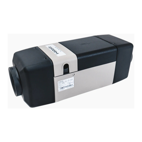
Figure 1: Air Top Evo 40/55 Air Heater Figure 2: Air Top Evo 40/55 Air Heater (without housing) Drive Unit The drive unit consists of the drive motor, the combustion air fan, the heating air fan and the intake housing. The combustion air fan supplies the air required for the combustion process from the combustion air inlet to the evaporator mount. -
Page 12: Heat Exchanger
Heat Exchanger The heat generated by combustion in the heat exchanger is given off to the cold air transported by the heating air fan. Figure 4: Heat Exchanger Evaporator Mount with Combustion Pipe The fuel is distributed via the metal fibre evaporator (fleece) in the evaporator mount. The mixture of fuel and air burns in the combustion chamber, thus causing the heat exchanger to become hot. -
Page 13: Glow Plug
Glow Plug The mixture of fuel and air is ignited by the glow plug when the heater is started. The glow plug designed as an electrical resistor is positioned in the burner assembly (evaporator mount with combustion pipe) on the side facing the flame. Figure 7: Glow Plug Exhaust Temperature Sensor The exhaust temperature sensor is a low-resistance PTC resistor which changes its resistance in dependence on the... -
Page 14: Overheat Temperature Sensor
Overheat Temperature Sensor The overheat temperature sensor measures the temperatures in the fin area of the heat exchanger during the entire heater operation. The control unit evaluates the signal and regulates the hot air outlet temperature and controls the overheating switch-off. Figure 9: Overheat Temperature Sensor Control Unit The control unit is the central component for ensuring the operating sequence. -
Page 15: Fuel Pump
Fuel Pump The fuel pump is a combined pumping, metering and shut-off system for the heater fuel supply. The Air Top Evo 40 / Air Top Evo 55 heaters must be operated with the DP 42 fuel pump. Figure 11: Fuel Pump Function Description Control Element Air Top Evo 40 / Air Top Evo 55 can be activated either with suitable control elements, e.g. -
Page 16: Switching On
Switching On Switch on heater. Set the control element to the required temperature. The starting process begins when the room temperature is below the set point temperature. Note: If the room temperature is above the selected set point temperature, only the drive motor with the combustion and heating air fan runs. -
Page 17: Control Mode
To increase the burner service life in continuous operation, the delivery capacity of the fuel pump is reduced for 10 seconds every 10 minutes. In addition, the heating mode is briefly interrupted after every 8 hours and then automatically restarted in the same way as for a control break. -
Page 18: Fault Switch-Off
Fault Switch-Off Errors on the various heater components and faults in the starting process and in heating mode are identified in the control unit. For safety reasons, the fuel pump will be switched off after all detected faults. The heater is switched off and switches into the fault lock-out mode. -
Page 19: Technical Data
Certain errors result in the errors being added up in the error memory. If the number of errors in the error memory have exceeded a limit, the heater changes over to the heater lock-out. The maximum number of errors in the error memory or the error memory limit is defined by Webasto. Cancel Heater Lock-Out The heater lock-out can be cancelled: –... - Page 20 Heater Operation Air Top Evo 40B Air Top Evo 55B Air Top Evo 40 D Air Top Evo 55 D Type test permit EMC: E1 03 5529 (Air Top Evo 40 / Air Top Evo 55) Heater: E1 00 0385 (Air Top Evo 40) Heater: E1 00 0386 (Air Top Evo 55) Model...
-
Page 21: Troubleshooting
If a malfunction occurs, a flashing code is displayed on the operating indicator or a fault code F .. on the combination timer. In addition, the heater can be checked using a personal computer (see Webasto PC Thermo Test PC Diagnosis operating manual). -
Page 22: Error Symptoms During Function
If serious malfunctions, such as overheating or failure to start, occur with increasing frequency, then the heater is permanently locked out and can only be returned to operation following repairs by Webasto trained professionals. When equipped with a combination timer, a fault code output appears on the display after a malfunction occurs until the heater malfunction has been eliminated. - Page 23 Fault Fault (group) Additional information during PC Troubleshooting code diagnostic F 01 No start/no flame formation 02 Even after the restart, no flame has Check fuel supply (tank empty, lines blocked). formed Check exhaust temperature sensor for 82 No start in test deposits from outside through exhaust fitting 83 Maximum feed rate exceeded and clean carefully if necessary.
-
Page 24: Maintenance Display In Control Element
Fault Fault (group) Additional information during PC Troubleshooting code diagnostic F 15 Not available 4F Upper limit of exhaust temperature F 16 Exhaust temperature exceeded Check free through-flow of combustion air and exhaust system, check CO setting, clean exceeded soot from heat exchanger if necessary F 17 Exhaust gas temperature 1A Short circuit to ground in exhaust... -
Page 25: Settings
PC (personal computer) Webasto Diagnosis Adapter incl. software Diagnosis Adapter ID No. 9009064_ is available from Webasto. Display of fault memory, operating data and control unit information. Reference heater Air Top Evo 40 / Air Top Evo 55 The reference heater must be subjected to continual operating checks. -
Page 26: Adjusting Co 2 Content
NOTE: If a fault occurs which cannot be detected with this procedure, the unit/component must be sent in to the Webasto Warranty Department. NOTE: Damage caused by soiling will not be recognized by Webasto! Air Top Evo 40 / Air Top Evo 55 Service Manual... -
Page 27: Burner Component Assembly
Graph legend (1) Replace component. Send defective components (not entire heater) to Webasto within warranty period. (2) Replace component and continue. (3) Replace heater. Send defective heater to Webasto within warranty period. (4) Continue. 6.4.1 Burner Component Assembly See Figure 34, Items 3 and 7. -
Page 28: Resistance Test Of Exhaust Temperature Sensor
6.4.2 Resistance Test of Exhaust Temperature Sensor See Figure 34, Item 10. During the test with a digital multimeter, the exhaust temperature sensor is to have the following values: Resistance at 20°C: 2,160 ± 3.2 ohms Test current: < 5 mA Procedure Test or measuring Visual... -
Page 29: Heating Air Fan Component
6.4.3 Heating Air Fan Component See Figure 30, Item 1 Procedure Test or measuring Visual equipment Visual inspection – Deformation – Magnets present – Locking lug broken Air Top Evo 40 / Air Top Evo 55 Service Manual... -
Page 30: Glow Plug Component
6.4.4 Glow Plug Component See Figure 34, Item 8 Note: The resistance test must be carried out with an ohmmeter suitable for small resistance values. A resistance test with a simple digital multimeter is too inaccurate to find the precise values. A new glow plug can be measured to act as a reference. -
Page 31: Drive Unit Component
6.4.5 Drive Unit Component See Figure 30, Item 2 Procedure Test or measuring Visual equipment Visual inspection Continuity measurement Digital multimeter Drive motor start-up Voltage source IMPORTANT Ensure correct polarity (+)/(-) (-) = black Subjective test (+) = red Air Top Evo 40 / Air Top Evo 55 Service Manual... -
Page 32: Overheat Temperature Sensor Component
6.4.6 Overheat Temperature Sensor Component See Figure 30, Item 9 During the resistance test with a digital multimeter, the overheat temperature sensor must have values in accordance with the following chart: Temperature in °C Figure 13: Characteristic resistance value of a PT 2000 Overheat Temperature Sensor in the temperature range 10 °C to 30 °C Air Top Evo 40 / Air Top Evo 55 Service Manual... - Page 33 Procedure Test or measuring Visual equipment Visual inspection Visual inspection Visual inspection Resistance measurement Digital multimeter Air Top Evo 40 / Air Top Evo 55 Service Manual...
-
Page 34: Control Unit Component
– PC (personal be tested in the reference computer) heater and conduct the – Webasto function test again Diagnosis Adapter – Reference heater Air Top Evo 40 / Air Top Evo 55 Service Manual... -
Page 35: Heater Component
6.4.8 Heater Component Description Procedure Test or measuring equipment Remove upper shell from heater and pull component connector off control unit PCB. Wire colors of individual components: Glow plug (yellow), Drive unit (black/red), Exhaust temperature sensor (white) Resistance component Resistance measurement Digital multimeter and continue Resistance component... - Page 36 Continuity Digital multimeter and continue measurement Function test – Heater test bench – CO measuring unit – PC (personal computer) – Webasto Diagnosis Adapter – Reference heater Function test Air Top Evo 40 / Air Top Evo 55 Service Manual...
-
Page 37: Wiring Diagrams
– Heater test bench measurement – CO measuring unit – PC (personal computer) Conduct function test – Webasto Diagnosis Adapter with reference heater. – Reference heater Adjust the reference unit after 5 minutes to CO nominal value in accordance with graphic... -
Page 38: Figure 14: Connector Assignment On Control Unit
Figure 14 shows the plug assignment on the control unit. See Section 7.2 for wiring diagram legends. IMPORTANT: The use of force when pressing on the connectors can destroy the mechanical coding, i.e. the reverse polarity protection or the correct assignment of the connection is no longer ensured. This can then result in considerable damage to the heater. -
Page 39: Figure 15: Wiring Diagram For Air Top Evo 40 / 55, 12V / 24V With Rheostat
Figure 15: Wiring Diagram for Air Top Evo 40 / 55, 12V / 24V with rheostat Air Top Evo 40 / Air Top Evo 55 Service Manual... -
Page 40: Figure 16: Wiring Diagram For Air Top Evo 40 /55, 12V/24V With Multicontrol (Mc04) Control Element
Figure 16: Wiring Diagram for Air Top Evo 40 /55, 12V/24V with MultiControl (MC04) control element Air Top Evo 40 / Air Top Evo 55 Service Manual... -
Page 41: Figure 17: Wiring Diagram For Air Top Evo 40 / 55, 12V / 24V With Smartemp
Figure 17: Wiring diagram for Air Top Evo 40 / 55, 12V / 24V with Smartemp Air Top Evo 40 / Air Top Evo 55 Service Manual... -
Page 42: Legend For Wiring Diagrams
Air Top Evo MultiControl (MC04) control element 1. Air Top Evo Multi Control (MC04) 3. Optional connection for: control element - Webasto Thermo Test PC Diagnosis 2. Observe colored markings 4. Heater wiring harness (available as an option) Legend for Wiring Diagrams... - Page 43 Multifunction (ventilation, boost, ECO) with control element MC02, only Boost activation for ambulance units Set-point sensor – CO2 setting Not used Set-point sensor + W-bus (Webasto Thermo Test PC-Diagnosis connection) Air Top Evo 40 / Air Top Evo 55 Service Manual...
- Page 44 Item Description Remarks Heater Air Top Evo 40 / 55 Control unit Control unit 1580 UniBox – Room temperature sensor Inside Overheat temperature sensor Overheating protection Room temperature sensor Outside Exhaust gas temperature sensor Overheating protection / flame monitor Glow plug –...
-
Page 45: Service Work
Note numbers: (1) With plus from Terminal 15/75 to Connection 10: Continuous operation with immediate heating as long as ignition is switched on. (2) All heater variants: W bus PC Diagnostics connection. Heater variants with Air Top Evo Multi Control (MC04) control element and combination timer. -
Page 46: Visual Inspections And Installation Instructions
This code indicates the need for maintenance/servicing of the heater to the user. The service signal is displayed for 10 seconds during each heater start-up and can be reset with the Webasto diagnosis with "Delete fault“ or by pulling the fuse. -
Page 47: Fuel System
The arrow indicates the direction of fuel flow. 8.6.2.2 Fuel filter If soiled fuel is to be expected, a suitable fuel filter (e.g. Webasto fuel filter) must be installed. Install vertically if possible, however at least horizontally (see Figure 20). -
Page 48: Combustion Air System
Figure 20: Fuel Filter, installation position and flow direction 8.6.3 Combustion air system Under no circumstances may the combustion air be taken from areas occupied by people. The combustion air intake opening must not point in the direction of travel. It must be located so that it cannot become clogged with dirt. NOTE: With benzin heaters, the combustion air must be extracted with a combustion air line at a position that is as cool as possible and protected from splashing water. -
Page 49: Combustion Air Inlet And Exhaust Lines
Figure 21: Permissible installation position of exhaust silencer (any desired flow direction) 8.6.5 Combustion air inlet and exhaust lines NOTE: To avoid damage to the fuel pump cable, it must be ensured that the combustion air intake and exhaust lines are not confused. -
Page 50: Electrical Connections
Figure 22: Permissible installation Figure 23: Remove the fastening plate on the fuse position of exhaust pipe end holder WARNING If the exhaust pipe ends is other than as shown in the Figure 22 it will pose a fire risk. 8.6.6 Electrical connections 8.6.6.1 Heater connection, control element The electrical connection is to be made as... -
Page 51: Figure 25: Rheostat
Figure 25: Rheostat NOTE: The fiber optic cable (Figure 25, "A") must be in contact with the rotary knob. NOTE: The connector housing can be locked (self-locking action) by simply pulling on the wiring harness. Figure 26: Disconnect the Plug Air Top Evo 40 / Air Top Evo 55 Service Manual... -
Page 52: Figure 27: Installation Example For Heater In Recirculated Air Mode
Figure 27: Installation example for heater in recirculated air mode 1. Control element 2. Heater 3. Fuse 4. Fuel standpipe 5. Fuel filter (optional) 6. Fuel pump 7. Exhaust silencer (optional) 8. Maximum permissible water passage height Air Top Evo 40 / Air Top Evo 55 Service Manual... -
Page 53: Removal And Installation
8.7.1.2 Installation 1. Move heater into installation position with new base seal and fasten with 4 nuts and lock washers (only use genuine Webasto nuts). 2. Tighten the nuts to 6 +1 Nm. 3. Fasten connection for fuel inlet on heater. -
Page 54: Carrying Out Modifications
9.1.1.1 Cleaning • All dismantled components must be cleaned and then dried. • Existing seal residues on the components must be completely and carefully removed. 9.1.1.2 Visual inspection • Inspect all components for damage (cracks, deformation, wear, etc.) and replace if necessary. •... -
Page 55: Dismantling And Assembling
Figure 28: External room temperature sensor 1. Cover 2. External room temperature sensor 9.2 Dismantling and assembling 9.2.1 Remove housing parts 9.2.1.1 Cover for electrical connection The cover (1, Figure 29) can be carefully levered off using a blunt blade in the areas marked “X”. 9.2.1.2 Grilles (optional) for cold air inlet and hot air Outlet The grilles (6, Figure 29, optional) can be released by twisting them out of the latch and pulled off toward the front. -
Page 56: Replacing Control Unit
9.2.2.3 Cover for cold air inlet and hot air outlet NOTE: The covers for the cold air inlet and hot air outlet differ. The cover with the smaller opening at the front must be fitted on the heating air fan. Slide on the covers (3 and 5, Figure 29) until the 4 positioning holes engage properly in the locking lugs of the lower and upper cover. -
Page 57: Replacing Overheat Temperature Sensor
4. Install housing parts (see 9.2.2). 5. Install heater (see 8.7.1.2) 6. Check CO setting and adjust if necessary (see Section 6.3). 9.2.4 Replacing Overheat Temperature Sensor 9.2.4.1 Removal 1. Remove heater (see 8.7.1.1). 2. Remove housing parts (see 9.2.1). 3. -
Page 58: Replacing Exhaust Temperature Sensor
7. Remove and discard flat seal (7). 9.2.6.2 Installation 1. Make sure that sealing surfaces on drive unit (2, Figure 30) and on heat exchanger (8) are not damaged. 2. Lay new flat seal (7) on flange of drive unit (2). 3. -
Page 59: Figure 31: Cable For Exhaust Temperature Sensor
4. Remove drive unit (see 9.2.6.1). 5. Remove 2 screws (1, Figure 34) and take off spring clip (2). Discard spring clip (2). 6. Press out cable grommet on exhaust-temperature sensor connection cable toward inside out of heat exchanger (6). 7. -
Page 60: Replacing Evaporator Mount And Glow Plug
Figure 33: Top view of heat exchanger 4. Install drive unit (see 9.2.6.2). 5. Install control unit (see 9.2.3.2). 6. Fit heating air fan (see 9.2.5.2). 7. Install housing parts (see 9.2.2). 8. Install heater (see 8.7.1.2) 9. Check CO setting and adjust if necessary (see Section 6.3). -
Page 61: Change The Combustion Chamber And The Heat Exchanger
6. Fit new spring clip (2) with 2 screws (1). 7. Install drive unit (see 9.2.6.2). 8. Install control unit (see 9.2.3.2). 9. Install housing parts (see 9.2.2). 10. Install heater (see 8.7.1.2) 9.2.9 Change the combustion chamber and the heat exchanger 9.2.9.1 Removal 1. -
Page 62: Packaging, Storage And Shipping
10.1 General information The heater or its components which are sent to Webasto for testing or repair must be cleaned and packaged so that they are protected against damage when handled, transported and stored. An ambient temperature of +85 °C or –40 °C must not be exceeded for storage. - Page 63 4/2015...
Need help?
Do you have a question about the Air Top Evo 40 Series and is the answer not in the manual?
Questions and answers