
Related Manuals for Aaeon ACP-5210


Summary of Contents for Aaeon ACP-5210
- Page 1 M u l t i - T o u c h P a n e l P C A C P - 5 2 1 0 ACP-5210 21.5” Fanless Multi-Touch Panel PC AMD G-Series T56N Processor 2GB RAM Inside ACP-5210 Manual 1st Ed April 16, 2014...
-
Page 2: Copyright Notice
AAEON, assumes no liabilities resulting from errors or omissions in this document, or from the use of the information contained herein. AAEON reserves the right to make changes in the product design without notice to its users. - Page 3 M u l t i - T o u c h P a n e l P C A C P - 5 2 1 0 Acknowledgments AMD is trademark of Advanced Micro Devices, Inc. ® ® Microsoft Windows is a registered trademark of Microsoft Corporation.
-
Page 4: Packing List
A C P - 5 2 1 0 Packing List Before you begin installing your Panel PC, please make sure that the following items have been shipped: ACP-5210 Infotainment Multi-Touch Panel PC Power Adapter x 1 Product DVD Contains User’s Manual (in PDF format), Drivers and... - Page 5 M u l t i - T o u c h P a n e l P C A C P - 5 2 1 0 Safety & Warranty 1. Read these safety instructions carefully. 2. Keep this user's manual for later reference. 3.
- Page 6 M u l t i - T o u c h P a n e l P C A C P - 5 2 1 0 14. If any of the following situations arises, get the equipment checked by service personnel: a.
- Page 7 M u l t i - T o u c h P a n e l P C A C P - 5 2 1 0 Classification 1. Degree of production against electric shock: not classified 2. Degree of protection against the ingress of water: IPX1 3.
- Page 8 M u l t i - T o u c h P a n e l P C A C P - 5 2 1 0 This device complies with Part 15 FCC Rules. Operation is subject to the following two conditions: (1) this device may not cause harmful interference, and (2) this device must accept any interference received...
- Page 9 M u l t i - T o u c h P a n e l P C A C P - 5 2 1 0 UL Module Description ACP-5210 AC modules are developed to suitable for the Classification Mark requirement...
- Page 10 M u l t i - T o u c h P a n e l P C A C P - 5 2 1 0 Safety Symbol Description The following safety symbols are further explanations for your reference. Medical equipment with respect to electric shock, fire and mechanical hazards only in accordance with UL 60601-1, and CAN/CSA C22.2 NO.
- Page 11 M u l t i - T o u c h P a n e l P C A C P - 5 2 1 0 Below Table for China RoHS Requirements 产品中有毒有害物质或元素名称及含量 AAEON Panel PC/ Workstation 有毒有害物质或元素 部件名称 铅...
-
Page 12: Table Of Contents
1.4 General Information........... 1-7 Chapter 2 Hardware Installation 2.1 Safety Precautions ............ 2-2 2.2 A Quick Tour of the ACP-5210 ........2-3 2.3 2.5” Hard Disk Drive (HDD) Installation ....2-5 Chapter 3 AMI BIOS Setup 3.1 System Test and Initialization ........3-2 3.2 AMI BIOS Setup. - Page 13 M u l t i - T o u c h P a n e l P C A C P - 5 2 1 0 B.3 IRQ Mapping Chart ..........B-5 B.4 DMA Channel Assignments ........B-5 Appendix C Miscellanea C.1 General Cleaning Tips ..........
- Page 14 M u l t i - T o u c h P a n e l P C A C P - 5 2 1 0 Chapter General Information Chapter 1 General Information...
-
Page 15: Chapter 1 General Information
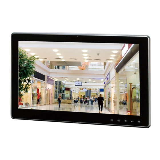
TFT LCD display, integrated multimedia functions make them the perfect platforms to build comprehensive lifestyle computing applications. The ACP-5210 includes all the features of a powerful computer into a slim and attractive chassis. The ACP-5210 has 250 nits TFT display with 1920x1080 resolution. This model equips two-point Multi-Touch Window design and is easy to clean. -
Page 16: Features
M u l t i - T o u c h P a n e l P C A C P - 5 2 1 0 1.2 Features 21.5” Full HD (1920x1080) Fanless TFT LCD Display Easy-To-Clean: Multi-Touch Window Design (Two-Point) ... -
Page 17: Specification
M u l t i - T o u c h P a n e l P C A C P - 5 2 1 0 1.3 Specification System Processor AMD G-Series T56N Processor, 1.6GHz System Memory DDR3 SODIMM x 1, Max. 4 GB (2 GB RAM inside) ... - Page 18 M u l t i - T o u c h P a n e l P C A C P - 5 2 1 0 IPX1 for top plastic chassis Mounting VESA 100, Wallmount Dimension 21.5”(W) x 13.7”(H) x 2.34”(D) (546mm x 348.1mm x 59.4mm) ...
-
Page 19: General Information
M u l t i - T o u c h P a n e l P C A C P - 5 2 1 0 Max. Colors 16.7 M colors (6/8-bit for R, G, B) Luminance (cd/m 250 cd/m ... -
Page 20: General Information
M u l t i - T o u c h P a n e l P C A C P - 5 2 1 0 1.4 General Information 1.3M Camera LCD On/Off Volume+ Volume- RFID Brightness+ Brightness- VESA 100 Speaker Speaker Chapter 1 General Information... - Page 21 M u l t i - T o u c h P a n e l P C A C P - 5 2 1 0 USB x 2 Power connector Line-out Smart Card Reader USB x 2 Power Switch USB x 2 COM x 1 LAN x 2...
-
Page 22: Chapter 2 Hardware Installation
M u l t i - T o u c h P a n e l P C A C P - 5 2 1 0 Chapter Hardware Installation Chapter 2 Hardware Installation... -
Page 23: Safety Precautions
M u l t i - T o u c h P a n e l P C A C P - 5 2 1 0 2.1 Safety Precautions Always completely disconnect the power cord from your board whenever you are working on it. -
Page 24: A Quick Tour Of The Acp-5210
M u l t i - T o u c h P a n e l P C A C P - 5 2 1 0 2.2 A Quick Tour of the ACP-5210 Mechanical Drawings Chapter 2 Hardware Installation... - Page 25 M u l t i - T o u c h P a n e l P C A C P - 5 2 1 0 Cable Cover (Optional) Note 1: You may turn on the power by cutting and destroying the protective cover as it shows below.
-
Page 26: Hard Disk Drive (Hdd) Installation
M u l t i - T o u c h P a n e l P C A C P - 5 2 1 0 2.3 2.5” Hard Disk Drive (HDD) Installation Step 1: Unscrew the rear cover screws (15 screws) Step 2: Remove EMI Cover (4 screws) Chapter 2 Hardware Installation... - Page 27 M u l t i - T o u c h P a n e l P C A C P - 5 2 1 0 Step 3: Remove HDD Bracket (4 screws) Step 4: Get the HDD and HDD Bracket ready Chapter 2 Hardware Installation...
- Page 28 M u l t i - T o u c h P a n e l P C A C P - 5 2 1 0 Step 5: Fasten the four screws to fix HDD Bracket and HDD Step 6: Connect the SATA and power cables to the HDD and fasten the four screws to fix the HDD Bracket Chapter 2 Hardware Installation...
-
Page 29: Chapter 3 Ami Bios Setup
M u l t i - T o u c h P a n e l P C A C P - 5 2 1 0 Chapter BIOS Setup Chapter 3 AMI BIOS Setup 3-1... -
Page 30: System Test And Initialization
3. The CMOS memory has lost power and the configuration information has been erased. The ACP-5210 CMOS memory has an integral lithium battery backup for data retention. However, you will need to replace the complete unit when it finally runs down. -
Page 31: Ami Bios Setup
M u l t i - T o u c h P a n e l P C A C P - 5 2 1 0 3.2 AMI BIOS Setup AMI BIOS ROM has a built-in Setup program that allows users to modify the basic system configuration. - Page 32 M u l t i - T o u c h P a n e l P C A C P - 5 2 1 0 Setup Menu Setup submenu: Main Options summary: (default setting) System Date Day MM:DD:YYYY Change the month, year and century. The ‘Day’ is changed automatically.
- Page 33 M u l t i - T o u c h P a n e l P C A C P - 5 2 1 0 Setup submenu: Advanced Options summary: (default setting) ACPI Settings System ACPI Parameters Trusted Computing Trusted Computing (TPM) Settings CPU Configuration CPU Configuration Parameters...
- Page 34 M u l t i - T o u c h P a n e l P C A C P - 5 2 1 0 System Super IO Chip Parameters F81866 H/W Monitor Monitor hardware status Chapter 3 AMI BIOS Setup 3-6...
- Page 35 M u l t i - T o u c h P a n e l P C A C P - 5 2 1 0 ACPI Settings Options summary: (default setting) ACPI Sleep State S3 (Suspend to RAM) Select the highest ACPI sleep state the system will enter when the SUSPEND button is pressed.
- Page 36 M u l t i - T o u c h P a n e l P C A C P - 5 2 1 0 Trusted Computing Options summary: (default setting) TPM SUPPORT Disabled Enabled En/Disable TPM support. O.S. will not show TPM. Reset of platform is required.
-
Page 37: Cpu Configuration
M u l t i - T o u c h P a n e l P C A C P - 5 2 1 0 CPU Configuration Chapter 3 AMI BIOS Setup 3-9... - Page 38 M u l t i - T o u c h P a n e l P C A C P - 5 2 1 0 SATA Configuration Options summary: (default setting) OnChip SATA Disabled Channel Enabled En/Disable Serial ATA OnChip SATA Type ACHI Legacy IDE...
- Page 39 M u l t i - T o u c h P a n e l P C A C P - 5 2 1 0 USB Configuration Options summary: (default setting) Legacy USB Support Enabled Disabled Auto Enables Legacy USB Support. AUTO option disables legacy support if no USB devices are connected.
- Page 40 M u l t i - T o u c h P a n e l P C A C P - 5 2 1 0 If Auto. USB devices less than 530MB will be emulated as Floppy and remaining as Floppy and remaining as hard drive. Forced FDD option can be used to force a HDD formatted drive to boot as FDD(Ex.
- Page 41 M u l t i - T o u c h P a n e l P C A C P - 5 2 1 0 F81866 Super IO Configuration Options summary: (default setting) Serial Port 1 Configuration Set Parameters of Serial Port 1 Keep last state Power Failure Always on...
- Page 42 M u l t i - T o u c h P a n e l P C A C P - 5 2 1 0 Serial Port 1 Configuration Options summary: (default setting) Serial Port Disabled Enabled En/Disable specified serial port. Change Settings Auto IO=3F8h;...
- Page 43 M u l t i - T o u c h P a n e l P C A C P - 5 2 1 0 F81866 H/W Monitor Chapter 3 AMI BIOS Setup 3-15...
- Page 44 M u l t i - T o u c h P a n e l P C A C P - 5 2 1 0 Setup submenu: Chipset Options summary: (default setting) North Bridge South Bridge Parameters South Bridge South Bridge Parameters Chapter 3 AMI BIOS Setup 3-16...
- Page 45 M u l t i - T o u c h P a n e l P C A C P - 5 2 1 0 North Bridge Options summary: (default setting) Graphics Configuration Configure Graphics Settings. Chapter 3 AMI BIOS Setup 3-17...
- Page 46 M u l t i - T o u c h P a n e l P C A C P - 5 2 1 0 Graphics Configuration Options summary: (default setting) DP1 Output LVDS Disabled NB PCIE Connect Type (Display device) Chapter 3 AMI BIOS Setup 3-18...
- Page 47 M u l t i - T o u c h P a n e l P C A C P - 5 2 1 0 South Bridge Options summary: (default setting) Power Mode ATX Type AT Type Select power supply mode. MiniCard &...
- Page 48 M u l t i - T o u c h P a n e l P C A C P - 5 2 1 0 SB HD Azalia Configuration Options summary: (default setting) HD Audio Azalia Auto Device Disabled Enabled Enable Or Disable HD Audio Azalia Device Chapter 3 AMI BIOS Setup 3-20...
- Page 49 M u l t i - T o u c h P a n e l P C A C P - 5 2 1 0 Setup submenu: Boot Options summary: (default setting) Quiet Boot Disabled Enabled En/Disable showing boot logo. Launch RTL8111E Disabled PXE OpROM.
- Page 50 M u l t i - T o u c h P a n e l P C A C P - 5 2 1 0 Setup submenu: Security Options summary: (default setting) Administrator Password/ Not set User Password You can install a Supervisor password, and if you install a supervisor password, you can then install a user password.
- Page 51 M u l t i - T o u c h P a n e l P C A C P - 5 2 1 0 Setup submenu: Save & Exit Options summary: (default setting) Save Changes and Reset Reset the system after saving the changes Discard Changes and Reset Reset system setup without saving any changes...
-
Page 52: Chapter 4 Driver Installation
M u l t i - T o u c h P a n e l P C A C P - 5 2 1 0 Chapter Driver Installation 4 - 1 Chapter 4 Driver Installation... - Page 53 M u l t i - T o u c h P a n e l P C A C P - 5 2 1 0 The ACP-5210 comes with a DVD-ROM that contains all drivers and utilities that meet your needs.
- Page 54 M u l t i - T o u c h P a n e l P C A C P - 5 2 1 0 4.1 Installation: Insert the ACP-5210 DVD-ROM into the DVD-ROM Drive. And install the drivers from Step 1 to Step 5 in order. Step 1 – Install Chipset Driver 1.
- Page 55 M u l t i - T o u c h P a n e l P C A C P - 5 2 1 0 Step 4 – Install AHCI Driver Please refer to the Appendix D AHCI Setting Step 5 –...
-
Page 56: Appendix A Programming The Watchdog Timer
M u l t i - T o u c h P a n e l P C A C P - 5 2 1 0 Appendix Programming the Watchdog Timer Appendix A Programming the Watchdog Timer A-1... -
Page 57: Programming
M u l t i - T o u c h P a n e l P C A C P - 5 2 1 0 A.1 Programming ACP-5210 utilizes FINTEK 81866 chipset as its watchdog timer controller. Below are the procedures to complete its configuration and the AAEON initial watchdog timer program is also attached based on which you can develop customized program to fit your application. - Page 58 M u l t i - T o u c h P a n e l P C A C P - 5 2 1 0 There are three steps to complete the configuration setup: (1) Enter the MB PnP Mode; (2) Modify the data of configuration registers; (3) Exit the MB PnP Mode.
- Page 59 M u l t i - T o u c h P a n e l P C A C P - 5 2 1 0 Watch Dog Timer 1, 2, 3 Control Register (Index=F5h,F6h,FAh Default=00h) Appendix A Programming the Watchdog Timer A-4...
-
Page 60: F81866 Watchdog Timer Initial Program
M u l t i - T o u c h P a n e l P C A C P - 5 2 1 0 A.2 F81866 Watchdog Timer Initial Program Main aaeonSuperIOOpen(); aaeonWdtSetCountMode(BOOL bMinute); // Set wdt count mode aaeonWdtSetTimeoutCount(BYTE tTimeout);... - Page 61 M u l t i - T o u c h P a n e l P C A C P - 5 2 1 0 Void aaeonWdtSetTimeoutCount(BYTE tTimeout){ f81866SetLdn(0x07); f81866WriteByte(F81866_WDT_TIME_REG, tTimeout); Void aaeonWdtSetEnable(BOOL bEnable){ f81866SetLdn(0x07); if(bEnable){ f81866WriteByte(0x30, 0x01); WDT_BASE_ADDR = (f81866ReadByte(F81866_WDT_BASEADDR_REG_MSB) <<...
- Page 62 M u l t i - T o u c h P a n e l P C A C P - 5 2 1 0 Void aaeonSuperIOClose(){ aaeonioWritePortByte(F81866_INDEX, 0xaa); Appendix A Programming the Watchdog Timer A-7...
-
Page 63: Appendix B I/O Information
M u l t i - T o u c h P a n e l P C A C P - 5 2 1 0 Appendix I/O Information Appendix B I/O Information... -
Page 64: I/O Address Map
M u l t i - T o u c h P a n e l P C A C P - 5 2 1 0 B.1 I/O Address Map Appendix B I/O Information... - Page 65 M u l t i - T o u c h P a n e l P C A C P - 5 2 1 0 Appendix B I/O Information...
-
Page 66: St Memory Address Map
M u l t i - T o u c h P a n e l P C A C P - 5 2 1 0 B.2 1 MB Memory Address Map Appendix B I/O Information... -
Page 67: Irq Mapping Chart
M u l t i - T o u c h P a n e l P C A C P - 5 2 1 0 B.3 IRQ Mapping Chart B.4 DMA Channel Assignments Appendix B I/O Information... -
Page 68: Appendix C Miscellanea
M u l t i - T o u c h P a n e l P C A C P - 5 2 1 0 Appendix Miscellanea Appendix C Miscellanea C-... -
Page 69: General Cleaning Tips
M u l t i - T o u c h P a n e l P C A C P - 5 2 1 0 C.1 General Cleaning Tips You may need the following precautions before you begin to clean the computer. -
Page 70: Cleaning Tools
M u l t i - T o u c h P a n e l P C A C P - 5 2 1 0 C.2 Cleaning tools Although many companies have created products to help improve the process of cleaning your computer and peripherals users can also use household items to clean their computers and peripherals. - Page 71 M u l t i - T o u c h P a n e l P C A C P - 5 2 1 0 Cotton swabs - Cotton swaps moistened with rubbing alcohol or water are excellent tools for wiping hard to reach areas in your keyboard, mouse, and other locations.
-
Page 72: Scrap Computer Recycling
For the computers that are no longer useful or work well, please contact with worldwide distributors for recycling. The worldwide distributors show on the following website: http://www.aaeon.com/?TabIndex=Contact&TabID=Distributors Note: Follow the national requirements to dispose unit Appendix C Miscellanea... -
Page 73: Installing Accessories
M u l t i - T o u c h P a n e l P C A C P - 5 2 1 0 C.4 Installing Accessories Skype Phone Installation Step 1: Fasten the two screws(2-SELF TAPPING SCREWS) to fix the Skype Bracket with the ACP-5210 Appendix C Miscellanea C-... - Page 74 M u l t i - T o u c h P a n e l P C A C P - 5 2 1 0 MSR Installation Step 1: Fasten the two screws (2-SELF TAPPING SCREWS) to fix the MSR Bracket with the ACP-5210 Appendix C Miscellanea...
- Page 75 M u l t i - T o u c h P a n e l P C A C P - 5 2 1 0 Bar Code Scanner Installation Step 1: Fasten the three screws to fix the Bar Code Scanner with the backet Appendix C Miscellanea C-...
- Page 76 M u l t i - T o u c h P a n e l P C A C P - 5 2 1 0 Step 2: Fasten the two screws (2-SELF TAPPING SCREWS) to fix the Bar Code Scanner with the ACP-5210 Appendix C Miscellanea...
-
Page 77: Appendix D Ahci Setting
M u l t i - T o u c h P a n e l P C A C P - 5 2 1 0 Appendix AHCI Setting Appendix D AHCI Setting... -
Page 78: Setting Ahci
M u l t i - T o u c h P a n e l P C A C P - 5 2 1 0 D.1 Setting AHCI OS installation to setup AHCI Mode. Step 1: Copy the files below from “Driver DVD -> STEP4 - AHCI\WinXP\SB8xx_RAID_XP_3.2.1540.92”... - Page 79 M u l t i - T o u c h P a n e l P C A C P - 5 2 1 0 Step 3: BIOS Setup menu select “Advanced\OnChip SATA Type -> AHCI” Step 4: Setup OS Appendix D AHCI Setting...
- Page 80 M u l t i - T o u c h P a n e l P C A C P - 5 2 1 0 Step 5: Press “F6” Step 6: Choose “S” Appendix D AHCI Setting...
- Page 81 M u l t i - T o u c h P a n e l P C A C P - 5 2 1 0 ® Step 7: Choose “AMD A50M” Step 8: It will show the model number you select and then press “ENTER” Step 9: Setup is loading files Appendix D AHCI Setting...
Need help?
Do you have a question about the ACP-5210 and is the answer not in the manual?
Questions and answers