
Subscribe to Our Youtube Channel
Related Manuals for ekwb EXTREME 240


Summary of Contents for ekwb EXTREME 240
- Page 1 For EK-KIT X (R2.0) series units | 1st Revision, Nov 27th 2015 Starter Liquid Cooling Kit EXTREME 240 360 USER GUIDE...
-
Page 3: Safety Precautions
If there is any problem, contact the shop where you have purchased the problem to get a replacement or refund. 3. EKWB d.o.o. is not responsible for any damages due to external causes, including but not limited to, improper use, problems with electrical power, ac- cident, neglect, alteration, repair, improper installation and improper testing. -
Page 4: Table Of Contents
TABLE OF CONTENT SCOPE OF DELIVERY POSSIBILITIES OF EXPANDING THE SYSTEM REQUIRED TOOLS MAINTENANCE FREQUENTLY ASKED QUESTIONS QUICK INSTALLATION GUIDE TROUBLESHOOTING RADIATOR SPACE CONSTRAINT REQUIREMENTS GENERAL LIQUID COOLING PARTS CLEANING GUIDE DOZEN GOOD ADVICES FOR THE NEWCOMERS SUPPORT AND SERVICE WATER COOLING SYSTEM SOCIAL MEDIA GENERAL INFORMATION ON WATER BLOCK COMPATIBILITY... -
Page 5: Scope Of Delivery
SCOPE OF DELIVERY CPU water Block CPU Backplate mechanism Thermal grease CPU Mounting mechanism with AMD® mounting plate Fans Pump UNI Pump Bracket Reservoir (120mm Fan) Compression fi ttings Radiator Coolant Tube / 3 /... -
Page 6: Required Tools
ATX Bridging plug Fan cable Y-splitter LED light Installation manual REQUIRED TOOLS Phillips-head screwdriver Mixing bottle 1L Bottle of distilled water Pair of scissors / 4 /... -
Page 7: Radiator Space Constraint Requirements
RADIATOR SPACE CONSTRAINT REQUIREMENTS 130 mm (5,12 in) 60 mm (2,36 in) 130 mm (5,12 in) / 5 /... -
Page 8: Dozen Good Advices For The Newcomers
DOZEN GOOD ADVICES FOR THE NEWCOMERS 1. In order to lower shipping costs we have decided to enclose only the after the Radiator in the water loop. coolant concentrate for liquid cooling. Therefor you need to provide 1 litre 7. Generally, for optimal performance, the Pump should be positioned before (1L) of distilled water. -
Page 9: General Information On Water Block Compatibility
GENERAL INFORMATION ON WATER BLOCK COMPATIBILITY This CPU liquid cooling unit is pre-assembled for use with modern Intel desktop socket type motherboards. By default (out of the box) this water block supports the following CPU sockets: - Intel® Socket LGA-775 - Intel®... -
Page 10: Replacing The Jet Plate /Insert Procedure (Optional)
REPLACING THE JET PLATE /INSERT PROCEDURE (OPTIONAL) STEP 1 Please observe the table below to determine the optimal combination of insert and jet plate for your type of socket: Water block top Socket Optimal Insert Optimal Jet Insert pin AMD® AMx / FMx Insert LGA-775 Jet plate... -
Page 11: Installing The Water Block
INSTALLING THE WATER BLOCK LGA-2011(-3) SOCKET MOTHERBOARDS STEP 1 LGA-2011 M4 Prepare the foil bag with mounting mechanism, which is enclosed with the CPU LGA-2011 M4 Thumb Screw water block delivery. Thumb Screw Install four (4) specific LGA-2011 M4 thumb screws into four M4 threaded stubs on the LGA-2011 socket integrated latch mechanism (ILM). - Page 12 STEP 3.: Align the water block over the mounting screws on the LGA-2011(-3) motherboard with pre-installed CPU. Before proceeding with the installation It is mandatory to remove the protective foil from the backside of the water block. Thumb nut Place an enclosed compression spring and thumb nut over each M4 thumb screw.
-
Page 13: Lga-115X Socket Motherboards
LGA-115x SOCKET MOTHERBOARDS Outer part STEP 1 If already installed, please remove the motherboard from your computer and place it on an even surface with front facing down. STEP 2 Preparing backplate rubber gasket The enclosed rubber gasket is essential part of the backplate and mount- ing system and must be used every time you install this water block on your motherboard. - Page 14 STEP 5 Cleaning the CPU: Wipe the CPU’s contact surface (by using non–abrasive cloth or Q-tip, as shown on sample photo). Non-abrasive Applying thermal compound: EK recommends blob or line method of applying the cloth enclosed EK-TIM Ectotherm thermal compound to the CPU heat spreader (IHS) - see sample photo on right.
-
Page 15: Amd® Socket Motherboards
AMD® SOCKET MOTHERBOARDS M4x16 Screws STEP 1 Replacing the mounting plate: Place the water block on a neven surface and remove the four M4x16 DIN 7991 screws attaching the copper base to the top Intel® socket AMD® socket using 2,5mm Allen key in counter-clockwise direction. mounting plate mounting plate STEP 1... - Page 16 STEP 4 Removing of the original plastic hold-down clamps UNC 6-32 AMD® factory backplate and the factory backplate: Screws Using Philips-head screwdriver remove the four UNC 6-32 screws securing the original plastic hold-down clamps around the socket as shown on the sketch. Remove the original AMD®...
- Page 17 STEP 7 M4 Thumb Screw Prepare the foil bag with mounting mechanism, which is enclosed with the CPU water block delivery. Install four (4) M4 thumb screws onto your motherboard. It is mandatory to put washer 0.7mm plastic washer underneath each of the M4 thumb screws. Tighten the screws to the metal backplate until you reach the end of the thread.
- Page 18 STEP 9 Fitting Barb With EK-Supremacy EVO series water blocks it Fitting Ring is mandatory to use the port that is nearest to the center of the water block as INLET port. Mixing the ports may result in poor thermal performance Inlet port of the water block.
-
Page 19: Installing The Radiator And Fans
INSTALLING THE RADIATOR AND FANS OPTION #1: UNC 6-32 x 30 screw INSTALLING THE RADIATOR AND FANS STEP 1 Install the fans on the radiator. Ideally, the radiator should either: A) receive the coldest air possible (by placing the radiator on the air inlet) or B) serve as an overall hot air exhaust (by placing the radiator Radiator... -
Page 20: Installing The Radiator And Fans In One Go
STEP 4.: Install the compression fittings on both to both G1/4 extender openings on the radiator. Fitting Barb Tighten the fitting barbs in clockwise direction until the gasket underneath is compressed. The installation of the radiator- and radiator cooling fans is now complete. Fitting Ring OPTION #2: INSTALLING THE RADIATOR AND FANS IN... -
Page 21: Installing The Pump Unit
INSTALLING THE PUMP UNIT OPTION 1: INSTALLING THE PUMP ON THE CHASSIS BOTTOM Pump unit STEP 1 The KIT comes with pump unit with pre-installed anti-vibration decouplers. Take the unit and place it on the EK-UNI Pump Bracket (120mm Fan) Verti- 120mm fan UNI cal, as shown on the picture. -
Page 22: Installing The Pump On The Chassis Wall
STEP 3 Secure the M4x6 screws (from the previous step) with four M4 nuts and PVC Fitting Ring washers. Tighten them using 2,5mm Allen key with the screws. PC Chassis Fitting Barb Make sure that the screws are holding tight but do not exaggerate with the force applied. - Page 23 STEP 2 The position of the unit in the chassis depends on the fan mount- PVC washer PC Chassis ing holes and the hardware you have installed. Usually the chassis have Pre-drilled standard fan mounting holes on the sides one you should look for holes with spacing of 105mm.
-
Page 24: Installing The Reservoir
INSTALLING THE RESERVOIR STEP 1 The Kit X comes with Reservoir EK-RES X3 150 which has en- closed mounting clamps. M4x12 screw Your reservoirs outlet port, which is usually directed to- wards the pumps inlet port should be installed in same level or higher than the pump in order to allow easy Reservoir RES X3 priming. - Page 25 STEP 4 Push the reservoir against the clamps. It should PC Chassis smoothly slide and lock into them. These holders allow rotating the reservoir or sliding it up and down a bit – depends on the distance be- Mounting clamps tween the clamps.
-
Page 26: Connecting The Tubing
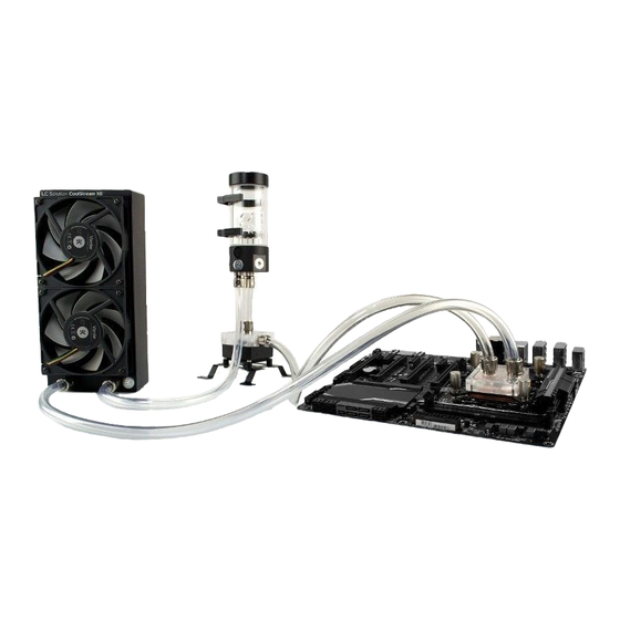
CONNECTING THE TUBING If you are expanding your loop with additional liquid CPU Waterblock COLD AIR cooling components please proceed to Page 31, chapter POSSIBILITIES OF EXPANDING THE SYSTEM. Reservoir STEP 1 Radiator In order to successfully route the tubing it is recommended with Fans that you check the water cooling scheme on the right picture. - Page 27 STEP 3 If you have assembled the components according to this installation manual you should have all the Fitting Ring compression fittings installed. In order to install the tubing onto the compression fittings you will have to remove the fitting ring by screwing it in counter- Fitting Ring clockwise direction.
-
Page 28: Electrical Connections
ELECTRICAL CONNECTIONS CONNECTING THE PUMP UNIT STEP 1 Pump Molex Connect the 4-pin Molex male connector to the male Molex connector of the header power supply. STEP 2 Take the 4-pin female connector and plug it to the male connector header located on the motherboard. -
Page 29: Recommended Filling And Leak-Testing Procedure
STEP 2 Connect the female EK-Cable Y splitter connector to the male connec- tor header located on the motherboard. Always use CPU-dedicated fan headers if possible. Always use CPU fan header. On majority of motherboards these headers usually offer best PWM regulation. RECOMMENDED FILLING AND LEAK- TESTING PROCEDURE STEP 1... -
Page 30: Filling The System For The First Time
FILLING THE SYSTEM FOR THE FIRST TIME STEP 1: Preparing the cooling liquid. The coolant comes in concentrated form. In order to prepare the cooling liquid you must take a 100mL clear coolant concentrate, which is enclosed with the kit, and mix it with 900mL of distilled water. Make sure you mix the mixture properly before pouring it into the water cooling loop. - Page 31 STEP 4 When you turn on the power supply the coolant should be pushed from the reservoir to other water cooling components, therefore you have to fill the coolant continuously while the pump is running. Alternatively you can cycle (turn on and of) the power supply in few second intervals to speed up the air bleeding process.
-
Page 32: Draining Of The Loop
DRAINING OF THE LOOP STEP 1 Before disassembling the water cooling loop it is mandatory turn off your computer and pull the power cord from the socket. Prepare some paper towels and stack them over the hardware. Take a container and put it under the reservoir unit. You can alternatively pull the reservoir off the clamps and outside the chassis if you don’t have enough space to put a container inside the chassis. -
Page 33: Possibilities Of Expanding The System
POSSIBILITIES OF EXPANDING THE SYSTEM The best part of custom water cooling loop is that the system can be extended and the cooling capacity can be extended almost without limitations. Rule of thumb is to use at least one 120mm radiator (section) per each water cooled component plus one ‘spare’. For example, if one is liquid cooling a CPU and a single high-performance graphics card it is recommended at least one 240mm (2x 120mm) radiator for good performance. -
Page 34: Maintenance
STEP 2 Measure the length of the tube that is needed to connect the CPU to GPU water block and the GPU water block to the reservoir. You can use a pair of scissors or a knife to cut the tube. You may need additional tubing to connect the water block. -
Page 35: Frequently Asked Questions
FREQUENTLY ASKED QUESTIONS Is this kit, namely the water block, compatible with narrow serv- Installing a typical GPU water block typically drop flow rates from 400L/h to er type LGA-2011 motherboard? How about older LGA-1366 about 350L/h. Adding two water blocks would result in flow rates of about and -755? 320L/h in the same scenario. -
Page 36: Troubleshooting
Upon exhausting all options please consult EK knowledge base at panel doors. Check the tubing for any signs of kink which restrict the flow. http://support.ekwb.com . Raise a question through EK Support ticketing system if needed. This is normally not the case when using original tubing. -
Page 37: General Liquid Cooling Parts Cleaning Guide
THE COOLER IS TOO LOUD: This kit is equipped with fast-spinning EK-Vardar high-static pressure PWM General Gigabyte Z170/X99 motherboard guide: controlled fans, which run at high speed if the UEFI/BIOS is not set to con- 1. Enter UEFI and go to M.I. T . - > PC Health Status trol fan speed. - Page 38 Upon cleaning is it necessary to flush the water blocks in water and rinse them 4. Cleaning POM (acetal) tops: POM (polyoxymethylene) or Acetal can with distilled water. After rinsing we recommend soaking the water blocks in withstand chemicals such as alcohol or acetone but EK recommend to use paper towels until completely dry.
-
Page 40: Support And Service
SUPPORT AND SERVICE For assistance please contact: http://support.ekwb.com/ EKWB d.o.o. Pod lipami 18 1218 Komenda Slovenia - EU SOCIAL MEDIA EKWaterBlocks @EKWaterBlocks ekwaterblocks EKWBofficial ekwaterblocks...
Need help?
Do you have a question about the EXTREME 240 and is the answer not in the manual?
Questions and answers