Table of Contents
Advertisement
Advertisement
Table of Contents

Related Manuals for ekwb Vector2


Summary of Contents for ekwb Vector2
- Page 1 EK-Quantum Vector² Xtreme RTX 3080/90 ABP Set D-RGB GPU WATER BLOCK USER GUIDE...
- Page 2 Please note the installation of the product is intented to be undertaken by an adequately trained and experienced person. You are installing the product at your own risk. If you are not properly trained or experienced or feel unsure about the installation procedure, please refrain from installing the product yourself and contact our tech support for assistance.
-
Page 3: Table Of Contents
TABLE OF CONTENTS BOX CONTENTS WATER BLOCK DIMENSIONS TECHNICAL SPECIFICATIONS AND WATER BLOCK PARTS NICKEL PLEXI PREPARING THE GRAPHICS CARD REMOVING THE STOCK COOLER CLEANING THE PCB PREPARING THE WATER BLOCK FOR INSTALLATION CUTTING AND PLACING THERMAL PADS APPLYING THERMAL COMPOUND ATTACHING THE WATER BLOCK ATTACHING THE ACTIVE BACKPLATE FITTINGS AND TUBING... -
Page 4: Box Contents
BOX CONTENTS EAN: 105161 M2.5x4 AX1 Screw (9 pcs) M2.5x8 AX1 Screw (1 pc) Standoff Ø4.5/2.5 (1 pc) EK-Quantum Vector Xtreme RTX 3080/90 ABP Set D-RGB M3x10 AX1 Screw (1 pc) Polyamid Washer M2.5 0.5mm (9 pcs) Standoff M2.5-M3 x 6.6mm (1 pc) EK-Loop Multi Allen Key (1 pc) Quantum Plug (2 pcs) Terminal OR - Vector... -
Page 5: Water Block Dimensions
WATER BLOCK DIMENSIONS 308.5 mm 212.5 mm 184.5 mm - 5 -... -
Page 6: Technical Specifications And Water Block Parts
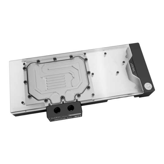
TECHNICAL SPECIFICATIONS AND WATER BLOCK PARTS NICKEL PLEXI - Dimensions: (LxHxW): 308.5 x 148 x 41 mm - D-RGB LED count: 30 - D-RGB cable length: 50 cm - D-RGB connector 3-pin 5V digital LED header Position Description Quantity 105139 Coldplate (Nickel) 105142 Top plate (Plexi) -
Page 7: Preparing The Graphics Card
PREPARING THE GRAPHICS CARD STEP 1 REMOVING THE STOCK COOLER Place your graphics card on the flat surface and carefully remove the stock cooler. Do not forget to unplug all the LED and fan connectors. Pay attention to the following steps when installing the EK-Quantum Vector Xtreme RTX 3080/3090 water block onto your graphics card. -
Page 8: Preparing The Water Block For Installation
PREPARING THE WATER BLOCK FOR INSTALLATION STEP 1 DO NOT M3 x 10 AX1 First, remove the terminal badge which is attached to the REMOVE SCREW terminal with two magnets. Under the badge, unscrew three (3) THE UPPER screws M4 x 20 DIN7984. Additional eight (8) screws M3 x 10 AX1 TERMINAL need to be removed (as shown in the image). -
Page 9: Cutting And Placing Thermal Pads
STEP 3 Unscrew eight (8) M2.5-M3 x 6.6 standoff with the included tool (EK-Plug out Spludger Tool). Make sure not to unscrew the M2.5-M3 x 6.6 M3.5-M2.5 x 11.3 standoff! In case the M3.5-M2.5 x 11.3 standoff STANDOFF unscrews, carefully tighten it back with the 4 mm wrench. After removing the standoffs, the PCB cardboard needs to be removed. -
Page 10: Applying Thermal Compound
STEP 2 Once cut to size, thermal pads should be placed on the PCB, as Thermal Pad - 120 x 16 x 1.0 mm illustrated below. EK made sure to provide you with more than an adequate quantity of thermal pads to complete this Step. Before attaching the PCB to the Water Block, make sure all the Thermal Pads are placed correctly! For this step, you will need:... -
Page 11: Attaching The Water Block
ATTACHING THE WATER BLOCK STEP 1 Carefully position the water block with preinstalled standoffs on the graphics card. During this process, make sure you have aligned mounting holes of the PCB with holes of the water block. Pay attention not to use too much force when pressing the block down to the PCB since chip dies are prone to cracking. - Page 12 Screws must be present in the places marked on the picture. STEP 2 STEP 3 Place the M2.5-M3 x 6.6 Standoff in each of the eight (8) mounting M2.5-M3 x 6.6 STANDOFF holes of the standoff M3.5-M2.5 x 11.3 (as shown in the image) and tighten them evenly with the EK-Plug-Out Spludger Tool.
-
Page 13: Attaching The Active Backplate
ATTACHING THE ACTIVE BACKPLATE STEP 1 Thermal Pad F – 1.0 mm (120 x 16 mm) After attaching the water block, a few more thermal pads need to be placed on the backside of the GPU PCB. Once cut to size, thermal pads should be placed on the PCB, as illustrated. - Page 14 STEP 2 Put two O-rings 14 x 1 into slots on the cold plate. Then carefully ACTIVE BACKPLATE place the active backplate on standoffs as shown in the image. While putting the active backplate on the PCB, make sure the O-rings stay in the slots.
-
Page 15: Fittings And Tubing
FITTINGS AND TUBING STEP 1 Screw-in two (2) G1/4 threaded male fittings. Attach the liquid cooling tubes and connect the water block to the cooling loop. EK- PLUG G1/4 Do not forget to plug the remaining two openings using the enclosed EK-Plug G1/4 or its equivalent. EK recommends using EK fittings with all EK water blocks. -
Page 16: Connecting The D-Rgb Led Strip
CONNECTING THE D-RGB LED STRIP STEP 1 Plug the 3-pin connector of the distribution plate D-RGB LED light to the D-RGB HEADER on the motherboard. The LED will work if the pin layout on the header is as follows: +5V, Digital, Empty, Ground. -
Page 17: Warranty
Removing the label will void the leak-free guarantee, but not the guarantee on the product itself. Any other RMA issues can be reported to EK Customer Support at www.ekwb.com/support for further analysis. - 17 -... -
Page 18: Support And Service
SUPPORT AND SERVICE In case you need assistance or wish to order spare parts or a new mounting mechanism, please contact: https://www.ekwb.com/customer-support/ For spare parts orders, refer to the page with “TECHNICAL SPECIFICATIONS AND WATER BLOCK PARTS” where you can find the EAN number of each part you might need.
Need help?
Do you have a question about the Vector2 and is the answer not in the manual?
Questions and answers