Advertisement
Quick Links
Advertisement

Related Manuals for ekwb EK-Quantum Magnitude sTRX4


Summary of Contents for ekwb EK-Quantum Magnitude sTRX4
- Page 1 EK-Quantum Magnitude sTRX4 CPU WATER BLOCK USER GUIDE...
- Page 2 Please, read the manual carefully before beginning with the installation process. For updates, you can visit our official website www.ekwb.com. Before you start using this product please follow these basic guidelines: Carefully read the manual before beginning with the installation process.
-
Page 3: Table Of Contents
TABLE OF CONTENT BOX CONTENTS WATER BLOCK DIMENSIONS TECHNICAL SPECIFICATIONS AND WATER BLOCK PARTS CHANGING THE COLDPLATE CONNECTING THE D-RGB LED STRIP TESTING THE LOOP SUPPORT AND SERVICE SOCIAL MEDIA - 3 -... -
Page 4: Box Contents
Magnitude Screw M3 x 9 (4 pcs) Magnitude sTRX4 Standoff (4 pcs) PVC Washer M2.5 (5 pcs) Magnitude Spring M3 x 10 (4 pcs) Allen Key 2.5 mm (1 pc) EK-Quantum Magnitude sTRX4 Thermal Grease (1 pc) - 4 -... -
Page 5: Water Block Dimensions
WATER BLOCK DIMENSIONS 21.10 mm 85 mm 14 mm 46 mm 29 mm - 5 -... -
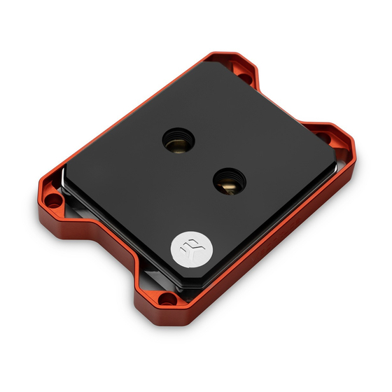
Page 6: Technical Specifications And Water Block Parts
TECHNICAL SPECIFICATIONS AND WATER BLOCK PARTS By default (out of the box), this water block supports the EK Badge following CPU sockets: - AMD Socket sTRX4 Top Plate (Plexi/Acetal/Brass) - AMD Socket TR4 (Socket SP3r2) - AMD Socket SP3 Technical Specifications: Main O-Ring - Dimensions (L x H x W): 85 x 120 x 21 mm - D-RGB (Addressable RGB) Wire Harness Cable Length: 500 mm... -
Page 7: Changing The Coldplate
CHANGING THE COLDPLATE STEP 1 Cleaning the CPU: Wipe the CPU’s contact surface with a non- abrasive cloth or Q-tip. Non-Abrasive Cloth STEP 1 STEP 2 Applying Thermal Compound: Apply the enclosed thermal grease (thermal compound) on the CPU heat spreader (IHS) as shown in the image. - Page 8 STEP 3 Before proceeding with installation, it is mandatory to remove the protective foil from the backside of the water block. Placing the Water Block on the Motherboard: Place your motherboard on an even surface and remove the Mounting Mechanism from the plastic bag. Install four (4) Standoffs tightly into the ILM Heat Sink studs by hand.
- Page 9 STEP 5 Tighten the screws in a cross pattern using the enclosed Allen Key. Stop tightening when every screw is flush with its hole inside the frame! STEP 5 STEP 6 FITTING RING Installing Fittings and Tubing: Screw-in two (2) G1/4 threaded male fittings.
- Page 10 You can also rotate the INLET/OUTLET port by following the further steps. M3 x 14 7991DIN STEP 1 Unscrew the eight (8) M3X14 DIN7991 screws using the 2mm Allen COLDPLATE Key and remove the colplate from the water block (as shown on the photo).
- Page 11 STEP 3 Carefully place the rotated brass insert back into the top. Make sure that the insert and jet plate O-ring’s remain in place. STEP 3 STEP 4 You can now replace the coldplate and screws (M3 X 14 DIN7991). M3 x 14 7991DIN Do not use the excessive force (Max torque: 0.55Nm).
-
Page 12: Connecting The D-Rgb Led Strip
STEP 5 The installation is now complete and the flow direction can be reversed. INLET STEP 5 CONNECTING THE D-RGB LED STRIP STEP 1 Plug the 3-pin D-RGB connector from the CPU water block to the D-RGB Header on your motherboard or controller. The LED strip will work only if the pin layout on the header is as follows: +5V, Data, Empty, Ground. -
Page 13: Testing The Loop
TESTING THE LOOP To ensure the installation of EK components was successful, we recommend you perform a 24-hour leak test. When your loop is complete and filled with coolant, connect the pump to a PSU outside your system. Do not connect power to any of the other components. -
Page 14: Support And Service
SUPPORT AND SERVICE In case you need assistance, please contact: https://www.ekwb.com/customer-support/ EKWB d.o.o. Pod lipami 18 1218 Komenda Slovenia - EU SOCIAL MEDIA EKWaterBlocks @EKWaterBlocks ekwaterblocks EKWBofficial ekwaterblocks...
Need help?
Do you have a question about the EK-Quantum Magnitude sTRX4 and is the answer not in the manual?
Questions and answers