
Related Manuals for ekwb Vector 2 FTW3 RTX 3080/90 ABP


Summary of Contents for ekwb Vector 2 FTW3 RTX 3080/90 ABP
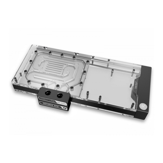
- Page 1 EK-Quantum Vector² FTW3 RTX 3080/90 ABP Set D-RGB GPU WATER BLOCK WITH ACTIVE BACKPLATE USER GUIDE...
- Page 2 Please, read the manual carefully before starting the installation process. For updates, you can visit our official website www.ekwb.com. Before you start using this product, please follow these basic guidelines: Carefully read the manual before beginning with the installation process.
-
Page 3: Table Of Contents
TABLE OF CONTENTS BOX CONTENTS WATER BLOCK DIMENSIONS PREPARING THE GRAPHICS CARD REMOVING THE STOCK COOLER CLEANING THE PCB PREPARING THE WATER BLOCK FOR INSTALLATION CUTTING AND PLACING THERMAL PADS APPLYING THERMAL COMPOUND ATTACHING THE WATER BLOCK ATTACHING THE ACTIVE BACKPLATE FITTINGS AND TUBING INSERTING THE GRAPHICS CARD INTO THE CHASSIS CONNECTING THE D-RGB LED STRIP... -
Page 4: Box Contents
BOX CONTENTS EAN: 104906 M2.5x4 AX1 Screw (9 pcs) M2.5x8 AX1 Screw (1 pc) Standoff Ø4.5/2.5 (1 pc) EK-Quantum Vector FTW3 RTX 3080/90 ABP Set D-RGB M3x10 AX1 Screw (1 pc) Polyamid Washer M2.5 0.5mm (9 pcs) Standoff M2.5-M3 x 6.6mm (1 pc) EK-Loop Multi Allen Key (1 pc) Quantum Plug (2 pcs) Nut M2.5 (2 pcs) -
Page 5: Water Block Dimensions
WATER BLOCK DIMENSIONS 328.1 mm 123.7 mm 41 mm 95.7 mm 35.5 mm - 5 -... -
Page 6: Preparing The Graphics Card
PREPARING THE GRAPHICS CARD STEP 1 REMOVING THE STOCK COOLER Place your graphics card on a flat surface and use the Phillips head screwdriver to remove the thirteen (13) marked screws, the Stock Backplate, and the Stock Cooler Backplate from the backside of the GPU. -
Page 7: Preparing The Water Block For Installation
PREPARING THE WATER BLOCK FOR INSTALLATION STEP 1 M3x10 AX1 First remove the terminal badge which is attached on the terminal with two magnets. Under the badge, unscrew three (3) screws M4x20 DIN7984. Additional nine (9) screws M3x10 AX1 needs to be removed as shown in the image. -
Page 8: Cutting And Placing Thermal Pads
STEP 3 M2.5-M3x6.6 Unscrew nine (9) M2.5-M3x6.6 standoff with the included tool STANDOFF (EK-Plug out Spludger Tool). Make sure not to unscrew the M3.5-M2.5x11.3 standoff! In case that M3.5-M2.5x11.3 standoff unscrews, carefully tighten it back with 4mm wrench. After removing the standoffs, the PCB cardboard (Printed Circuit Board cardboard) needs to be removed. -
Page 9: Applying Thermal Compound
STEP 2 Thermal Pad F 1.0mm The cardboard is printed in scale 1:1. Cut thermal pads to the size printed on the cardboard. Once cut to size, thermal pads should be placed on the PCB. Be careful to choose the right thermal pad thickness. -
Page 10: Attaching The Water Block
ATTACHING THE WATER BLOCK STEP 1 Carefully position the water block with preinstalled standoffs on the graphics card. During this process, make sure you have aligned mounting holes of the PCB with holes of the water block. Pay attention not to use too much force when pressing the block down to the PCB since chip dies are prone to cracking. -
Page 11: Attaching The Active Backplate
STEP 3 M2.5-M3x6.6 Place the M2.5-M3 x 6.6 Standoff in each of the nine (9) mounting STANDOFF holes of the standoff M3.5-M2.5 x 11.3 (as shown in the image) and tighten them evenly with the EK-Plug-Out Spludger Tool. Do not use excessive force! For this step, you will need: EK-Plug Out Spludger Tool STEP 3... - Page 12 3080/ 3080Ti: CAUTION: You must remove the protective foil from both sides of the thermal pad before installation. G1.5 Thermal Pad - 120 x 16 x 2.0 mm Thermal Pad - 120 x 24 x 1.5 mm G1.5 3090: G1.5 Thermal Pad - 120 x 16 x 1.0 mm Thermal Pad - 120 x 16 x 2.0 mm Thermal Pad - 120 x 24 x 1.5 mm...
- Page 13 STEP 2 ACTIVE BACKPLATE Put two O-rings 14x1 EPDM 50 into slots on the copper plate. Then carefully place active backplate on standoffs as shown in the image. While putting the active backplate on the PCB, make sure the O-rings stay in the slots. Before attaching the Active Backplate on the PCB, make sure all the Thermal Pads are placed correctly! O-RING 14x1...
-
Page 14: Fittings And Tubing
FITTINGS AND TUBING STEP 1 Screw-in two (2) G1/4 threaded male fittings. Attach the liquid cooling tubes and connect the water block to the cooling loop. EK- PLUG G1/4 Do not forget to plug the remaining two openings using the enclosed EK-Plug G1/4 or its equivalent. EK recommends using EK fittings with all EK water blocks. -
Page 15: Connecting The D-Rgb Led Strip
CONNECTING THE D-RGB LED STRIP STEP 1 Plug the 3-pin connector of the distribution plate D-RGB LED light to the D-RGB HEADER on the motherboard. The LED will work if the pin layout on the header is as follows: +5V, Digital, Empty, Ground. -
Page 16: Warranty
Removing the label will void the leak-free guarantee, but not the guarantee on the product itself. Any other RMA issues can be reported to EK Customer Support at www.ekwb.com/support for further analysis. - 16 -... -
Page 17: Support And Service
SUPPORT AND SERVICE In case you need assistance or wish to order spare parts or a new mounting mechanism, please contact: https://www.ekwb.com/customer-support/ For spare parts orders, refer to the page with “TECHNICAL SPECIFICATIONS AND WATER BLOCK PARTS” where you can find the EAN number of each part you might need.
Need help?
Do you have a question about the Vector 2 FTW3 RTX 3080/90 ABP and is the answer not in the manual?
Questions and answers