Table of Contents
Advertisement
Quick Links
Advertisement
Table of Contents

Related Manuals for advidia B-210


Summary of Contents for advidia B-210
- Page 1 B-210 Outdoor 2MP Mini PTZ User’s Manual...
-
Page 2: Table Of Contents
Table of Contents Precautions ............. 4 Safety Instructions ..................6 Introduction ....Error! Bookmark not defined. Package Contents ..................7 Physical Description ................. 8 Mounting Options ..................10 Installing the Camera on a Surface ..... 12 Step 1: Drill the Holes ................12 Step 2: Open the Dome Cover .............. - Page 3 How to Remove / Install the Camera Module......... 32 How to Remove the Camera Module ............ 32 How to Install the Camera Module ............33 How to Replace the Dome Cover ............34 How to Insert / Remove a Memory Card ..........38 How to Insert the Memory Card ............
-
Page 4: Precautions
Precautions Read these instructions You should read all the safety and operating instructions before using this product. Heed all warnings You must adhere to all the warnings on the product and in the instruction manual. Failure to follow the safety instruction given may directly endanger people, cause damage to the system or to other equipment. - Page 5 Federal Communications Commission Statement This equipment has been tested and found to comply with the limits for a class B digital device, pursuant to Part 15 of the FCC Rules. These limits are designed to provide reasonable protection against harmful interference in a residential installation.
-
Page 6: Safety Instructions
Safety Instructions Cleaning Disconnect this video product from the power supply before cleaning. Attachments Do not use attachments not recommended by the video product manufacturer as they may cause hazards. Do not use accessories not recommended by the manufacturer Only install this device in a dry place protected from weather Servicing Do not attempt to service this video product yourself. -
Page 7: Package Contents
Package Contents Camera Mounting Screw Kit Hexagon Screwdriver Drill Template Conduit Grommet Cable Grommet Drill Template Terminal Block Terminal Block Quick Installation Guide (for Power) (for DI/DO and Audio In/Out) -
Page 8: Physical Description
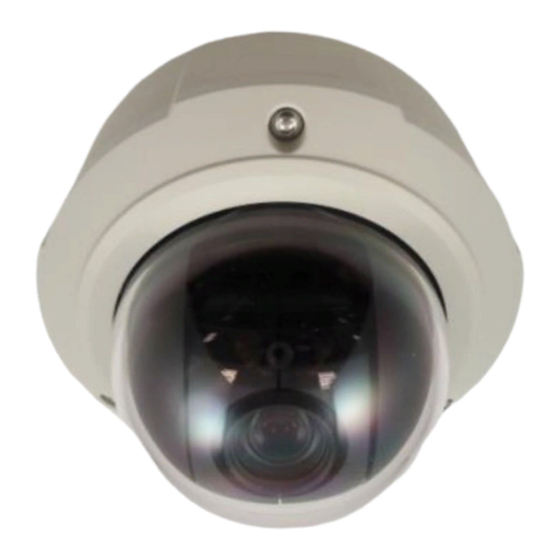
Physical Description camera module Illustration. 1) Ethernet Port Connects to a network using an Ethernet cable. 2) DC 12V Power Input In case the camera is connected to a non-PoE (Power over Ethernet) switch, use this connector to connect the camera to an external power adapter (not included). See Connecting a Power Adapter (Optional) on page 26 for more information. - Page 9 4) Digital Input / Output (DI/DO) and Audio Input / Output This connector connects to digital input or output devices, such as an alarm trigger, panic button, etc., as well as audio input and output devices, such as microphones and speakers. Digital Input (DI) and Digital Output (DO) devices are used in applications like motion detection, event triggering, alarm notifications, 5) Memory Card Slot...
-
Page 10: Mounting Options
Mounting Options There are several mounting options that you can use to install the camera. Select the most suitable solution for your installation environment. Mount Types Accessories Surface Suitable when mounting the camera directly walls or ceilings Mount without extra accessories. See Installing the Camera on a Surface on page 12 for mounting instructions. - Page 11 B210-FM NOTE: For more information about the mounting solutions and accessories, please check the Advidia website. The above mounting accessories are not included in the package. Contact your sales agents to purchase.
-
Page 12: Installing The Camera On A Surface
Installing the Camera on a Surface This section details the procedures of installing the camera on a flat surface such as a hard or dropped ceiling and straight or tilted walls. Before installation, make sure the wall or the ceiling can bear more than the weight of the camera. -
Page 13: Step 2: Open The Dome Cover
Step 2: Open the Dome Cover NOTE: To avoid scratches or fingerprints on the dome cover, it is recommended to leave the protective plastic on the dome cover until the camera is completely installed. However, the plastic has been removed on some of the pictures in this documentation to show clarity of the procedures being described. -
Page 15: Step 3: Prepare For Waterproof And Connect The Cable
Step 3: Prepare for Waterproof and Connect the Cable The camera comes with two (2) grommets used for waterproof installation: Cable Grommet: For use with an Exterior-grade Ethernet cable. Exterior-grade Ethernet cables are already waterproof. See Waterproof Solution with Bare Cable page 16. -
Page 16: Waterproof Solution With Bare Cable
Waterproof Solution with Bare Cable This section describes the procedures in using the included cable grommet and an exterior-grade Ethernet cable. 1. Disassemble the cable grommet as shown below: Body Clamping Compression (with Washer) Sealing Insert 2. Insert the clamping nut into the Ethernet cable. 3. - Page 17 4. Attach the cable grommet body to the hole of the camera. Attach to Camera Side Hole Attach to Camera Bottom Hole 5. If the cable will be routed along the surface, pull the network cable through the side conduit hole. If the cable will pass through the surface, pull the network cable through the bottom conduit hole.
- Page 18 6. Insert the compression sealing insert into the cable grommet body and then attach the clamping nut to complete the cable solution. Same procedures apply to cable passing the surface or along the surface. NOTE: Make sure the clamping nut is tightly attached to the cable grommet body and the sealing insert is squeezed tightly.
-
Page 19: Waterproof Solution With Conduit
Waterproof Solution with Conduit This section describes the procedures to waterproof the cabling connections using the bundled conduit grommet and flexible conduit. This is the recommended solution if an exterior-grade Ethernet cable is not available or when other cables, such as power adapter, DI/DO devices, etc., will be connected to the camera. - Page 20 2. Disassemble the bundled conduit grommet as shown below: Sealing Lock Nut Insert Body Clamping Nut NOTE: In this installation, the conduit grommet body can be securely attached to the mount kit; therefore the use of lock nut is not necessary. Please set the lock nut aside. 3.
- Page 21 5. Insert the sealing insert and attach it at the end of the flex conduit. 6. Screw the conduit grommet body to the conduit hole of the camera. Attach to Side Conduit Hole Attach to Bottom Conduit Hole 7. If the cable(s) will be routed along the surface, skip this step. If the cable will pass through the surface, do the following: a.
- Page 22 b. Insert the sealing nut into the conduit grommet body and then tighten the clamping nut as tightly as possible to complete the cable solution. 8. If only the network cable will be connected, connect the network cable to the Ethernet port of the camera at this point.
- Page 23 10. Connect the network cable to the Ethernet port and other cables (if any) to the corresponding connectors on the camera. If necessary, install also the memory card at this point. 12V Power Connector Digital Input / Output (DI/DO) and Audio Input / Output Ethernet Port Connector Memory Card Slot...
-
Page 24: Step 4: Install The Camera To The Surface
Step 4: Install the Camera to the Surface Align the camera screw holes and the cable hole (if necessary) to the holes on the surface and attach the three (3) supplied screws (with rubber) to secure the camera. CAUTION: When using electric screwdrivers, be careful not to touch the internal camera components while attaching the screws. -
Page 25: Step 6: Connect To The Network
2. Remove the plastic covering the dome cover. Final installation will look like the illustration below. Step 6: Connect to the Network Connect the other end of the network cable to a switch or injector. Then, connect the switch or injector to a network or PC and a power source. -
Page 26: Other Connections
Other Connections This section describes the procedures in preparing the external devices that you can connect to the camera. The camera supports DC12V power input, Digital Input and Output (DI/DO) and Audio Input and Output devices using the included terminal blocks. The use of these devices, however, is optional. - Page 27 3. Connect the wire with the white stripe to the 12V pin and the other to the GND pin. 4. Tighten the screws of the 12V pin and the GND pins to secure the wire connection. 5. Set the prepared power adapter for connection later. Below is an example of a power adapter with an attached terminal block.
-
Page 28: Connecting The Di/Do And Audio Devices (Optional)
Connecting the DI/DO and Audio Devices (Optional) Depending on your surveillance needs, you may connect digital input or output or audio input / output devices to your camera. The camera comes with one (1) terminal block for both digital and audio input / output devices. - Page 29 Device Connection design TTL - compatible logic levels To trigger (low) Logic level 0: 0V ~ 0.4V Voltage Normal (high) Logic level 1: 3.1V ~ 30V Current 10mA ~ 100mA Connection design Transistor (Open Collector) Voltage & Current < 24V DC, < 50mA Typical Connection Based on these specifications, if the DI device has a voltage of 0V ~ 30V or the DO device has a voltage of <...
-
Page 30: How To Connect Audio Devices
High Voltage DO Device Connection Even though the camera provides 12V power, this may not be enough for some high voltage DO devices, such as a ceiling light or a motor that opens or closes a gate. In this case, there is a need to connect an external relay. - Page 31 Press and hold the orange tab as you insert the wire through the pin slot, then release the orange tab to secure the wire. For DI/DO Use To connect audio devices, map the pins to one of the pin combinations below: Device Mapping Instructions AO_GND...
-
Page 32: Other Adjustments And Accessories
Other Adjustments and Accessories How to Remove / Install the Camera Module How to Remove the Camera Module The camera module must be removed from the housing in the following situations: To install a memory card To connect a digital input / output device ... -
Page 33: How To Install The Camera Module
How to Install the Camera Module 1. Align the camera module to the guides on the housing. 2. Tighten the three (3) screws to secure the camera module to the housing. 3. Close the dome cover. -
Page 34: How To Replace The Dome Cover
How to Replace the Dome Cover For more discrete surveillance needs, the bundled dome cover can be replaced with a smoke, vandal proof cover available for purchase. To replace the dome cover, do the following: 1. Loosen the three (3) screws to open the dome cover. 2. - Page 35 4. Remove dome cover from the cover housing. 5. Remove the rubber from the dome cover. 6. Insert the rubber into the replacement dome cover. 7. Insert the replacement dome cover into the cover housing.
- Page 36 8. There are 3 indents on the cover housing; note the indent (a) which is on the center of the extended curve of the cover. Place the bracket on the cover housing with the arrow on the bracket aligned to the indent (a). 9.
- Page 37 10. Fit the screw into the spring wire that is attached to the camera. Note the screw placement as shown below. 11. There are two (2) screw holes on the bracket, attach the screw to the right screw hole using a screwdriver.
-
Page 38: How To Insert / Remove A Memory Card
How to Insert / Remove a Memory Card The camera supports local video recording or saving of snapshots to a memory card. NOTE: Supports microSDHC and microSDXC cards. How to Insert the Memory Card 1. Remove the camera module from the housing. See How to Remove the Camera Module on page 328. -
Page 39: Accessing The Camera
If you work with Advidia cameras regularly, then there is even a better way to discover the cameras in the network – by using The Advidia B Series Camera Finder Utility. The IP Utility is a light software tool that can not only discover the cameras, but also list lots of valuable information, such as IP and MAC addresses, serial numbers, firmware versions, etc, and allows quick configuration of multiple devices at the same time. - Page 40 With just one click, you can launch the IP Utility and there will be an instant report as follows: You can quickly notice the camera model in the list. Click on the IP address to automatically launch the default browser of the PC with the IP address of the target camera filled in the address bar of the browser already.
- Page 41 Use the default IP address of a camera: If there is no DHCP server in the given network, the user may have to assign the IP addresses to both PC and camera manually to make sure they are in the same network segment. When the camera is plugged into network and it does not detect any DHCP services, it will automatically assign itself a default IP: 192.168.0.100...
- Page 42 The easiest way to assign cameras the IP addresses is by using the Advidia B Series Camera Finder Utility: With the procedure shown above, all the cameras will have unique IP addresses, starting from 192.168.0.101.
-
Page 43: Access The Camera
It is a free and open source cross-platform multimedia player. Disclaimer Notice: Advidia does not guarantee the compatibility of its cameras with VLC player or QuickTime – since these are third party softwares. The third party has the right to modify their utility any time which might affect the compatibility. - Page 44 Assuming that the camera’s IP address is 192.168.0.100, you can access it by opening the Web browser and typing the following address into Web browser’s address bar: http://192.168.0.100 Upon successful connection to the camera, the user interface called Web Configurator would appear together with the login page.
Need help?
Do you have a question about the B-210 and is the answer not in the manual?
Questions and answers