Table of Contents
Advertisement
Quick Links
Advertisement
Table of Contents

Subscribe to Our Youtube Channel
Related Manuals for Ganz ZC-YHW702 Series


Summary of Contents for Ganz ZC-YHW702 Series
-
Page 1: Ccd Camera
Operation Manual CCD CAMERA ZC-YHW702 Series... - Page 2 Read the “Instructions for Use” prior to operation. Retain this operation manual for future reference. Follow these important safety instructions at all times. Heed the following explanations of “Warning” and “Caution”. Indicates danger of death or injury to the user if not operated properly.
- Page 3 Caution Turn off the power before connecting any devices. Failing to do so could result in electric shock or fire. Make sure that connecting cables are inserted fully. Failing to do so can result in fire. Disconnect the power and cables before moving the device. Failing to do so can result in injury and damage to the device.
-
Page 4: Table Of Contents
Table of Contents Item Page Introduction Instructions for Use Component Names and Functions Lens Mounting Wiring Connector Applicable Lenses Lens Adjustment Back Focus Adjustment Connecting the Power Connecting the AC Power Connecting the DC Power Settings for Various Functions Settings Operation Setting Items Mode Select (MODE SELECT) Settings for the Exposure Function (CONFIGURATION) -
Page 5: Introduction
Introduction Thank you for purchasing our product. This device is a multifunctional, high performance CCD camera developed for high end security. The characteristics of this camera are as follows. (1) Wide dynamic range function (WD) Displays both light and dark objects at the same time (Dynamic range of 60-dB max). (2) Day and Night modes (DAY &... -
Page 6: Component Names And Functions
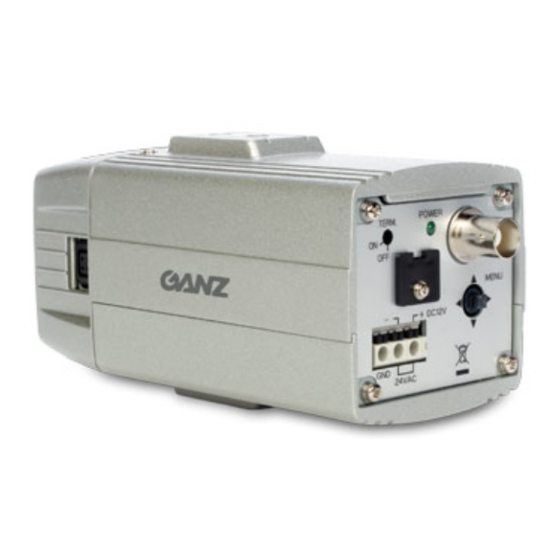
Component Names and Functions Figure 1 Rear View Top Front View Lens mount A suitable type CS mount lens may be attached. C mount lenses can be attached using a C/CS mount adapter. Back focus lock screw A ALLEN WRENCH can be inserted here to stabilize the lens mount using a screw to adjust the distance between the lens mounting surface and the imaging surface. -
Page 7: Lens Mounting
Lens Mounting This device uses a DC voltage auto iris lens. A VIDEO signal control lens can not be used. Wiring Connector Refer to chart 1 for the connector wiring diagram. Chart 1 Connector Auto iris lens Connector DC voltage drive Pin No. -
Page 8: Back Focus Adjustment
Back Focus Adjustment The factory settings include back focus adjustment for a CS mount lens. However, adjustment may be required depending on the lens used. Use the back focus adjustment function to do this. Adhere to the following adjustment procedure. Operating procedure 1. -
Page 9: Connecting The Power
Connecting the Power Use 24 V AC / 12 V DC for this device. Warning: Be careful not to short circuit the power cord when connecting it to the device. Connecting the AC Power Use 24 V AC (20.4 - 27.6 V AC) 50 Hz / 60 Hz to power the device. Refer to figure 5 as to connecting the power. -
Page 10: Settings For Various Functions
Settings for Various Functions This device is equipped with an OSD (On Screen Display) feature and various functions can be set using this camera’s monitor screen. A list of settings menu is as follows. MODE SELECT STANDARD DAY&NIGHT WIDE CASINO USER MODE RETURN CONFIGURATION... - Page 11 SYNC SELECT LL PHASE SHIFT SYNC MODE AUTO LL PHASE → Phase Value = 33 RETURN Notice) With AUTO settings CHROMA RY GAIN → BY GAIN → RY HUE → BY HUE → RETURN E-ZOOM POSITION ZOOM → OFF POSITION RETURN Notice) With Zoom settings PRIVACY MASKING...
-
Page 12: Settings Operation
Settings Operation This device is equipped with an OSD (On Screen Display) feature. Operate as follows to change settings using the menu. 1. Press and hold the function setting switch on the back panel for about two seconds. (Figure 1). 2. - Page 13 The details of each of the mode settings are as follows. STANDARD FUNCTION SET. CONFIGURATION → AUTO → NORMAL AE MODE SYNC SELECT → AUTO → WHITE BALANCE BRIGHT LEVEL → → CHROMA FLICKERLESS → → NORMAL GAMMA → → E-ZOOM SENS UP →...
-
Page 14: Settings For The Exposure Function (Configuration)
(2) Settings for the Exposure Function (CONFIGURATION) This is a menu to adjust the camera exposure. Two menus are available based on the AE MODE setting. A . For “AE MODE” settings other than "MANUAL" B. For “MANUAL” setting in “AE MODE” CONFIGURATION CONFIGURATION →... - Page 15 DAY & NIGHT This is used to switch between day (color) and night (black/white) settings. AUTO: This switches between color mode and black/white mode automatically based on the brightness of the screen. COLOR: Selects color mode. Selects black/white mode. EXT.: This switches modes based on an external control signal.
-
Page 16: Settings For Other Functions (Function Set.)
(3) Settings for Other Functions (FUNCTION SET.) This is a menu to set various functions other than exposure. FUNCTION SET. → SYNC SELECT → AUTO WHITE BALANCE → CHROMA → NORMAL GAMMA → E-ZOOM → CRISPNESS → PRIVACY MASKING → TITLE RETURN Figure 9-1 FUNCTION SET. - Page 17 (3-2) WHITE BALANCE WHITE BALANCE The mode for white balance can be selected. AUTO: White balance is adjusted automatically. HOLD: The white balance used right before changing to this mode is maintained. This is suitable for imaging in a location where lighting doesn’t change. Refer to the following setting method.
- Page 18 (3-5) E-ZOOM This operates the electronic zoom and electronic pan/tilt function. These functions are set using this menu. E-ZOOM POSITION ZOOM → 2.0 POSITION → RETURN Figure 9-5 E-ZOOM menu ZOOM This sets zoom magnification. OFF, 1.5, 2.0, 2.5 Note) “PRIVACY MASKING” and “AE MODE: WD” can not be used with this item setting. POSITION The frame position is set for zooming.
- Page 19 3. An arrow is displayed on the screen. Determine the position of the mask to be created using this arrow. First, move the arrow to upper left of mask to be created and select the position with the switch. Move the arrow next to the lower right, and mask will be created by selecting the position with the switch.
-
Page 20: Camera Setup (Camera Setup)
(4) Camera Setup (CAMERA SETUP) This device is equipped with an external control input terminal (RS-485) and settings for each function can be changed from an external unit. For details, refer to “External Control Signal Terminal”. CAMERA SETUP → ADDRESS →... -
Page 21: Mode Save (Mode Save)
(6) Mode Save (MODE SAVE) This saves the current settings. It loads the saved settings by selecting “USER MODE” from “MODE SELECT”. MODE SAVE CURRENT SETTINGS ARE SAVED. CANCEL Figure 12 MODE SAVE menu Operating procedure 1. After changing the settings, move the cursor to “MODE SAVE” and press the switch to display the "MODE SAVE"... -
Page 22: Initialize (Initialize)
(8) Initialize (INITIALIZE) This returns all settings to the initial factory settings. INITIALIZE ALL SETTINGS ARE IINITIALIZED CANCEL Figure 14 INITIALIZE menu Operating procedure 1. Move the cursor to “INITIALIZE” and press the switch to display the “INITIALIZE” screen. 2. Move the cursor to “OK” and press the switch to run initialization. 3. -
Page 23: External Control Signal Terminal
External Control Signal Terminal This device is equipped with an external control signal terminal for remote operation. Connection Refer following figure for connector wiring. Figure 16 Enlarged figure Pin No. Description A (+) B (-) A (+) B (-) DAY&NIGHT external control terminal Connect the supplied cable to the connector when this terminal is used and use a shielded twisted pair cable as an extension cable. -
Page 24: Settings
Settings Use the following procedure to set up the system using this terminal. Setting procedure 1. Connect the cables to each camera. 2. Turn the camera terminal SW which is set on terminal to ON. Set other cameras to OFF. (figure 1 ) 3. -
Page 25: Specifications
Specifications Model Name ZC-YHW702N ZC-YHW702P TV system NTSC Power supply 24 V AC ±15% (50 Hz / 60 Hz) / 12 V DC ±15% Power consumption 270 mA (24 V AC) / 390 mA (12 V DC) Imaging device 1/3-type interline transfer CCD (vertical double density register structure) Effective pixels Approx.
Need help?
Do you have a question about the ZC-YHW702 Series and is the answer not in the manual?
Questions and answers