Table of Contents
Advertisement
: May 15 2006
3
CONFIGURATION
[1]
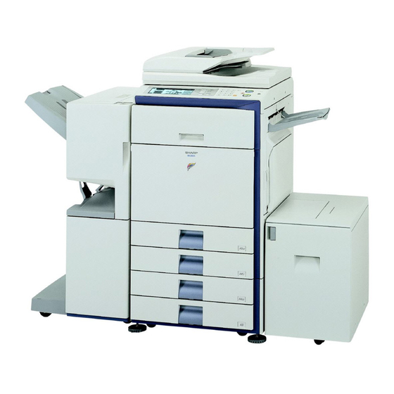
MX-2300G/N, MX-2700G/N
[2]
MX-DEX1/DEX2
(Stand/1x500 sheet paper drawer, Stand/2x500 sheet paper drawer)
[3]
[4]
[5]
[6]
[7]
[8]
[9]
AR-PN1A/B/C/D
[18]
3
Parts marked with "
" are important for maintaining the safety of the set. Be sure to replace these parts with
specified ones for maintaining the safety and performance of the set.
INSTALLATION MANUAL
DIGITAL FULL COLOR
MULTIFUNCTIONAL SYSTEM
MODEL
CONTENTS
(Main unit)
. . . . . . . . . . . . . . . . . . . . . . . . . . . . . . . . . . . . . . . . . . . 3-1
. . . . . . . . . . . . . . . . . . . . . . . . . . . . . . . . . . . . . 5-1
(Finisher)
. . . . . . . . . . . . . . . . . . . . . . . . . . . . . . . . . . . . . . . . . . . . . . . 6-1
(Punch module (For Inner Finisher))
(Paper pass unit, Saddle stitch finisher)
(Punch module (For Saddle stitch finisher))
. . . . . . . . . . . . . . . . . . . . . . . . . . . . . . . . . . . 10-1
. . . . . . . . . . . . . . . . . . . . . . . . . . . . . . . . . . . . . 12-1
. . . . . . . . . . . . . . . . . . . . . . . . . . . . . . . . . . . . . . . . . 13-1
SHARP CORPORATION
CODE: 00ZMX2700/I1E
MX-2300/2700 G
MX-2300/2700 N
. . . . . . . . . . . . . . . . . . . . . . . . . . . . . . . . 1-1
. . . . . . . . . . . . . . . . . . . . . . . . . . . . 4-1
. . . . . . . . . . . . . . . . . 7-1
. . . . . . . . . . . . . . . . . . . . . . . . . . . . . 11-1
. . . . . . . . . . . . . . . . . . . . . . . . . . 14-1
. . . . . . . . . . . . . . . . . . . . . . . . . . 15-1
. . . . . . . . . . . . . . . . . . . . . . 16-1
. . . . . . . . . . . . . . . . . . . . . . . . . . . . . . . 17-1
. . . . . . . . . . . . . . . . . . . . . . . . . . . . . . . . . 19-1
. . . . . . . . . . . . . . . . . . . . . . . . . . . . . . 20-1
. . . . . . . . . . . . . . . . . . . . . . . 21-1
This document has been published to be used
for after sales service only.
The contents are subject to change without notice.
. . . . 2-1
. . . . . . . . . . . . 8-1
. . . . . . . . . . . . 9-1
Advertisement
Table of Contents

Related Manuals for Sharp MX-2300 G


Summary of Contents for Sharp MX-2300 G
-
Page 1: Table Of Contents
" are important for maintaining the safety of the set. Be sure to replace these parts with specified ones for maintaining the safety and performance of the set. This document has been published to be used SHARP CORPORATION for after sales service only. The contents are subject to change without notice. -
Page 2: Mx-Trx1 (Exit Tray Unit)
: May 15 2006 MX2700N CONFIGURATION 1. Configuration A. Lineup (Main unit and option) 1. Reversing single pass feeder 12. Staple cartridge (MX-RPX1) 9. Finisher (Approx. 5000 x 3) (MX-FNX1) (MX-SCX1) PCL5c/PCL6 Network SPLC-c scanner driver driver (Sharpdesk 1 license) 2. - Page 3 : May 15 2006 B. Machine configuration MX-2300G MX-2300N MX-2700G MX-2700N Copier memory (Local memory) (MB) Printer memory (System memory) (MB) Copier GDI printer – – PCL printer OP*3 OP*3 PS printer OP*1 EFI printer – Main body LCD MONOCHROME HVGA 8.1" OP*4 Scanner OP *3...
- Page 4 MX2700N [1] MX-2300G/N, MX-2700G/N (4) Safety Be sure to properly ground the machine. 1. Installing (use) conditions (5) Power plug Check the form of the power plug. If the shape does not match, do Before installing the machine, check that the following installing not use it.
-
Page 5: Transit And Delivery
A. Implements, facility, and manpower (2) Dust If dust enters the machine, it may cause dirty copy and a paper It is recommendable to use a forklift for bringing in the machine for jam, resulting in a shortened lifetime. safety. If no forklift is available, man-power of four persons is required. - Page 6 D. Check the parts packed together Check that all the parts are in the package. Parts name Quantity Waste toner bottle unit Operation manual Operation manual pocket 4. Installation <Note before installation> * When connecting the main unit with the optional one-tier paper feed desk (MX-DEX1) or two-tier paper feed desk (MX-DEX2), first unpack and install the one-tier paper feed desk (MX-DEX1) or two-tier paper feed desk (MX-DEX2);...
- Page 7 : Jan. 15 2006 C. Primary transfer cleaning roller pressing/ (2) Scanner (2/3 mirror unit) lock release Transfer belt protect sheet removal Remove the optical unit fixing screw, and remove the note label. Open the front cover. B. Fusing heat roller pressing (F/R) Check that the lock is released as shown in (A).
- Page 8 : Jan. 15 2006, : Oct. 13 2006 Loosen the blue screw. D. Applying titanium hydroxide Remove the cleaner unit. Turn the blue screw (A) counterclockwise. Check to insure that the lock is released as shown with (B), and pull out the primary transfer unit toward you.
- Page 9 : Oct. 13 2006 Rotate the belt by amount 10 cm to move the application part (Application amount) to the surface. * Till the applied powder reaches the cleaner installation loca- tion. Little Moderate Much amount Face the primary transfer UN upward. * Face the primary transfer UN UPward from the cleaner UN Mount the cleaner frame UN on the primary transfer UN.
- Page 10 : Jan. 15 2006 E. Developing (each color) installation Install the DV cover in the arrow direction (A). * When installing the DV cover, be sure to engage the pawl Remove two fixing screws of the DV cover. with the boss. Hold the sections A, and remove the DV cover in the arrow Fix the DV cover with the two screws.
- Page 11 : Jan. 15 2006 Install each developer unit. F. Set the control level for the reference toner density * When installing the developer unit, be sure to check that the DV lock lever is open. Connect the earth cord and insert the power plug into the power outlet.
- Page 12 After entering the data, close the front cabinet. Remove the heat seal. Select K, C, M, Y and then press the [EXECUTE] button. The Open the front cover, and insert each toner cartridge. system then performs the simulation, samples the toner den- sity control sensor value, and sets (stores in memory) the average sensor detection level as the control level for the ref- erence toner density.
- Page 13 : Dec. 15 2005 H. Cleaning of LSU's dust-proof glass Replace the LSU claning bar to the front cover and attach the waste toner bottle unit. * Dust from the transfer belt or shutter or some other adjacent part may fall onto the LSU during transport or installation. Be sure to clean the dust-proof glass before checking the image quality.
- Page 14 J. Tray setup Select the paper size. (1) Touch the desired paper size. (1) Simulation setup (2) Touch the [OK] key. This is used to specify the paper type, paper size, and functions used for each paper tray. Press the [SYSTEM SETTINGS] key. System Settings SYSTEM Type...
- Page 15 : Oct. 13 2006 K. Specifications setup • ADJ 18: Copy image position, image loss adjustment Document table mode Used to set the specifications with SIM26 according to the cus- tomer's request. Place a scale on the document table. Enter the simulation 50-1 mode. SIM No Content Perform the image lead edge reference position adjustment.
-
Page 16: Auto Adjustment
: Oct. 13 2006 (5) Printer color balance adjustment Press [FACTORY] key, and press [EXECUTE] key. (Auto adjustment) a. Note for execution of the color balance adjustment CLOSE SIMULATION NO. 46-24 TEST (Auto adjustment) ENGINE HALFTONE AUTO ADJUSTMENT • The copy color balance adjustment must have been completed PLEASE SELECT THE MODE (FACTORY) OR (SERVICE) AND PLACE properly. - Page 17 : Oct. 13 2006 Press [OK] key. M. Function and operation check Check that the following operations are normal. CLOSE CLOSE SIMULATION NO.67-24 TEST Check items Equipped condition PRINTER ENGINE HALFTONE AUTO ADJUSTMENT MODE Key-in (operation panel) CONFIRM THE ADJUSTED PATCH AND PRESS [OK] TO REGISTER THIS PATCH DATA Display (operation panel) PRESS [REPEAT] TO CONTINUE THIS PROCEDURE.
- Page 18 : Dec. 15 2005 [2] MX-DEX1/DEX2 C. Check the packed items MX2700N Check that all the items are included in the package. 1. Unpacking A. Removal of the desk unit Names of bundles Quantity Right adjuster Fixing screws (M4 x 8) 2.
- Page 19 B. Installation of the adjuster Put the main unit on the desk unit. * Use man power of four persons or more to lift the main unit. Install the right adjuster (package part No. 1) to the desk unit. Turn each adjuster to fix the desk unit. * Place the main unit on the desk unit slowly by fitting the external lines.
- Page 20 Lift the connection plates on the right and left of the main unit Lift the connection plates, and fix them with the fixing screws. front side, and fix them with the fixing screws (package part No. 2). Replace the No. 3 and No. 2 trays to the original positions. Install the connection plate covers.
- Page 21 D. Release the lock E. Connector connection Pull out each tray. Remove the screw from the back of the main unit. Remove the connector cover. Connect the connector. Turn and remove the fixing material, and remove the caution sheet. Attach the removed fixing material to the position shown in the Split the removed connector cover along the perforated line.
- Page 22 F. Turn on the power of the main unit This screen allows you to configure the print off-center adjust- ment value for each paper feed tray. Connect the earth cord, and insert the power plug of the main <Detailed Description> unit into the power outlet.
- Page 23 : Dec. 15 2005 [3] MX-TRX1 MX2700N Open the front cabinet. Turn OFF the power switch in the front cabinet of the main unit. 1. Unpacking A. Removal of the exit tray unit Remove the earth cord and disconnect the power plug of the main unit from the power outlet.
- Page 24 Remove the screw, and remove the paper exit cover. C. Turn on the power of the main unit. Connect the earth cord, and insert the power plug of the main unit into the power outlet. Connect the connector, and install the exit roller unit (package part No.
- Page 25 : Dec. 15 2005 2. Installation [4] MX-RPX1 MX2700N <Note before installation> 1. Unpacking * Before installation, check to insure that the data lamp on the operation panel does not blink or light up. A. Removal of the RSPF A. Turn off the power of the main unit. Turn OFF the power switch on the operation panel.
- Page 26 Remove the screws, and remove the glass holder (A). Loosen the screw on the angle adjustment plate in the rear side of the machine and lower the angle adjustment plate. Slide the table glass (B) in the arrow direction. Remove the screws, and remove the glass holding left OC (C). Arrange the SPF glass unit (D) (package part No.
- Page 27 C. RSPF height adjustment Make an RSPF height adjustment sheet Cut copy paper in the longitudinal direction. 20mm A4/Letter size Perform the adjustment according to the flowchart below. <Flow chart> <Work procedure> Check section A. Place the RSPF height adjustment sheet between section A Start of the adjustment and the SPF glass height adjustment resin surface (a), and...
- Page 28 Check section B. Place the RSPF height adjustment sheet between section B and the SPF glass height adjustment resin surface (a), and close the RSPF unit. Slowly pull out the RSPF height adjustment sheet. Check to insure that a slight resistance is felt when pulling out the RSPF height adjustment sheet.
- Page 29 D. Turn on the power of the main unit. E. RSPF diagonal adjustment Connect the earth cord, and insert the power plug of the main Set a test chart (A3) on the RSPF document tray, and make a unit into the power outlet. copy.
- Page 30 Close the RSPF unit, and loosen the hex nut of the RSPF G. Adjustment with the simulation diagonal adjustment screw section. (1) SPF size width detection level adjustment Turn the hex wrench of the RSPF diagonal adjustment screw Go to SIM53-6. to adjust the alignment.
- Page 31 (2) Auto void adjustment (SPF adjustment) <Adjustment Item List> Go to SIM 50-28. • SPF original leading edge adjustment (front side) • SPF original off-center adjustment (front side) • SPF original sub-scan magnification adjustment (front side) SIMULATION NO.50-28 CLOSE TEST SPF adjustment patterns are loaded into the SPF.
-
Page 32: Mx-Lcx1 (Large Capacity Tray)
: Dec. 15 2005 [5] MX-LCX1 MX2700N Remove the paper feed desk fixing screw. 1. Unpacking A. Removal of the large capacity tray unit NOTE: Before turning on the power, check to insure that the fixing screw of the tray is removed. If the power is turned on without removing the fixing screw, a trouble may be resulted. - Page 33 Open the front cabinet. Disengage the pawl, and remove the right adjuster. Turn OFF the power switch in the front cabinet of the main unit. Remove the screw cap, and remove the screw. Remove the earth cord and disconnect the power plug of the main unit from the power outlet.
- Page 34 : Jun. 15 2006 Insert the temporarily fixed screw B into the key hole in the Check to insure that the height adjustment check rib of the connection unit (package part No. 2), and temporarily fix the large capacity tray unit and the axis line of the mounting plate connection unit.
- Page 35 In the case of a shift to the right, press the front upper section Connect the connector, and tighten the screw. and fit the height adjustment check rib so that it is in the same line with the axis line of the mounting plate upper. Insert the large capacity tray unit into the main unit.
- Page 36 a. Side plate size switch Loosen the fixing screw (flat screw 1pc) of the auxiliary guide. Remove four fixing screws (blue screws) which are fixing the Set the mark position ( ) of the auxiliary guide and the cas- upper and the lower sections of the side plate F and the side sette R to the size from A4 to LT, and fix with the fixing screw plate R.
- Page 37 Slightly push the tray, restore the stopper to the original posi- Loosen the stopper fixing screw (1 pc) on the right lower side tion, and fix the fixing screw. of the tray so that the stopper does not function. Pull out the tray again until it stops. At that time, check to insure that the stopper pawl is engaged with the stopper reception of the large capacity tray unit.
- Page 38 Slightly push the tray, restore the stopper to the original posi- F side R side tion, and fix the fixing screw. b. Auxiliary guide size switch * Since the auxiliary guide setting is not required, fix the auxiliary At that time, check to insure that the stopper pawl is engaged guide to either of A4 or LT.
- Page 39 Open the front cabinet. Check that the adjustment pattern image is printed in the cor- rect position. Turn ON the power switch in the front cabinet of the main unit. Measure the dimensions of the void areas on the front- and rear-frame sides of the adjustment pattern image, and make sure that the following conditions are met: A-B = 0...
- Page 40 Pull out the tray again until it stops. b. When the shift is in the rear side To adjust the print line in the direction B from the paper center as shown in the figure: Loosen two fixing screws (red screws) of the front/rear size guide adjustment plate, and move the size guide adjustment plate in the direction B (F side) by the shift amount, and tighten the red fixing screws (2 for each).
-
Page 41: Mx-Fnx1
: Dec. 15 2005 [6] MX-FNX1 B. Removal of the fixing tape and protection MX2700N material Remove the fixing tape and protection material. 1. Unpacking A. Removal of the inner finisher C. Check the packed items Check that all the items are included in the package. * When removing the inner finisher, lift it as shown in the table below. - Page 42 2. Installation B. Removal of the paper holding arm unit Push up the section A to disengage the pawl, and remove the <Note before installation> paper holding arm and the paper holding arm holder together * Before starting installation, check to insure that the data lamp on as a unit.
- Page 43 Disengage two pawls, and remove the paper exit tray cover. Install the front slide rail (A) (package part No. 2) with the three fixing screws (package part No. 8), and install the left front cover (B) (package part No. 6) with one fixing screw (package part No.
- Page 44 D. Connector connection 12) After pushing the intermediate rail of accuride, insert the fin- isher slide stopper (package part No. 7) between the rear slide Remove the protection material and fixing tape. rail and the accuride. Fix it with the coin screw (package part No. 10). 13) Install the front open/close cover (package part No.
- Page 45 [For RSPF] (package part No. 12) Turn ON the power switch on the operation panel. Cleaning of the document scan section CAUTION When streaks appear on copy or scan images, open the automatic document feed unit and clean the document scan section with the glass cleaner (accessory).
-
Page 46: Mx-Pnx1A/B/C/D
: Dec. 15 2005 [7] MX-PNX1A/B/C/D MX2700N C. Check the packed items Check that all the items are included in the package. 1. Unpacking A. Removal of the punch unit Packed part names Quantity Punch position label (For scanner) Punch position label (For RSPF) 2. - Page 47 Open the front cabinet. Remove the coin screw, and remove the finisher slide stopper. Turn OFF the power switch in the front cabinet of the main unit. Slide the inner finisher further more. Remove the earth cord and disconnect the power plug of the main unit from the power outlet.
- Page 48 Remove the screw, and remove the dummy punch unit. 11) Remove the dust box. 12) Fix the punch cover and the band together with one screw. Fix the punch unit with a screw. * When installing the punch unit, be careful not to bump it against the drawer connector.
- Page 49 D. Turn on the power of the main unit 16) Slide the inner finisher to the original position, and close the front cover. Connect the earth cord, and insert the power plug of the main unit into the power outlet. C.
-
Page 50: Mx-Rbx1, Mx-Fnx2
: Dec. 15 2005 [8] MX-RBX1, MX-FNX2 MX2700N C. Check the packed items Check that all the items are included in the package. 1. Unpacking the MX-RBX1 A. Removal of the interface pass unit Packed part names Quantity Right cover plate Interface left cabinet Reverse tray Fixing screw A... - Page 51 Remove the earth cord and disconnect the power plug of the Disengage the pawls, and remove the paper exit tray cover. main unit from the power outlet. Remove the screws, and remove the paper exit tray. B. Removal of the paper holding arm unit Push up the section A to disengage the pawl, and remove the paper holding arm and the paper holding arm holder together as a unit.
- Page 52 Insert the rib of the interface left cabinet (package part No. 2) Install the front cabinet upper, and fix with the screws. into the slit on the lower surface of the scanner left cabinet. Install the interface left cabinet with the fixing screw A (pack- age part No.
- Page 53 : Dec. 15 2005 C. Check the packed items 3. Unpacking the MX-FNX2 Check that all the items are included in the package. A. Removal of the saddle finisher Packed part names Quantity Paper exit tray Connection plate Staple unit Staple cartridge Fixing screw A Fixing screw B...
- Page 54 : Dec. 15 2005 Install the Operation Manual storage cover (which was As shown in the figure, rotate the roller rotation knob so that removed from the machine) to the saddle finisher. the triangle mark is fit with the indication. First, insert the pawl on the lower side of the Operation Manual pocket.
- Page 55 D. Installation of the paper exit tray Loosen the fixing screw of the adjustment section on the front side. If the guide pin is inserted smoothly, tighten the fixing Engage the pawls (two positions) of the paper exit tray (pack- screws of the adjustment section on the front/rear sides.
- Page 56 Loosen four fixing screws of the adjustment section, and turn Connect the finisher connector with the connector of the main the height adjustment screws on the front/rear sides to adjust unit, and tighten the screw. so that the clearances are even. G.
- Page 57 H. Turn on the power of the main unit I. Storage of the paper entry guide Connect the earth cord, and insert the power plug of the main When the punch unit is not installed, store the paper entry unit into the power outlet. guide (package part No.
- Page 58 2. Installation MX2700N [9] AR-PN1A/B/C/D <Note before installation> 1. Unpacking * Before starting installation, check to insure that the data lamp on the operation panel does not light up or blink. A. Removal of the punch unit A. Turn off the power of the main unit Turn OFF the power switch on the operation panel.
- Page 59 Remove the screw, and remove the pawl (A) on the rear cabi- net in the arrow direction (B), and remove the rear cabinet upper in the arrow direction (C). Remove the interface harnesses (2 pcs.) from the outlet port of the rear cabinet upper.
- Page 60 C. Replacement of the paper entry paper guide Remove the hook (boss) on the upper side of the paper entry paper guide with a screwdriver. Remove the dust box of the punch unit. Remove the paper entry paper guide. Remove the guide from the dust box. The guide is not used in the MX-FNX2.
- Page 61 10) Install the punch unit and fix it with the screws. Connect the 13) Pass the interface harnesses (2 pcs.) through the rear cabinet connector. upper. While opening the upper door, install the rear cabinet upper, and fix it with screws. Boss hole Boss hole Boss...
- Page 62 16) Install the saddle finisher to the main unit. Apply the dust box label (package part No. 4) in position as shown in the figure. E. Turn on the power of the main unit D. Punch position label attachment Connect the connector. Attach the label to the position indicated in the figure.
- Page 63 Open the front cabinet. Check to confirm that the LED1 on the finisher control PWB flashes at a certain interval. Turn ON the power switch in the front cabinet of the main unit. Set the DIP SW 2 and 5 to ON to execute the mechanism ini- tializing of the finisher.
-
Page 64: Mx-Pbx1 (Printer Expansion Kit)
MX2700N [10] MX-PBX1 Click [START] button and [My computer], and double-click [CD-ROM] icon. • In the case of Windows 98/Me/Nt 4.0/2000, double-click [My 1. Unpacking computer] and double-click [CD-ROM] icon. Double-click [SETUP] icon. Confirm the contents of "Software License Agreement" dis- played on the screen and press [YES]. - Page 65 Set the image of this machine. Set the image of this machine displayed on the printer driver setting screen according to the peripheral devices installed to the machine. a) Select the peripheral device installed to the machine. b) Click [OK] button. •...
-
Page 66: Mx-Frx1, Mx-Frx1U (Data Security Kit)
B. Pull out the control PWB. MX2700N [11] MX-FRX1, MX-FRX1U • If cables are connected to the control PWB unit, remove all cables. 1. Unpacking Push the location indicated in the illustration to unlock, and remove the ozone filter cover from the right rear cabinet. A. - Page 67 D. Remove the rear cabinet. F. Attach the DOCC PWB. • If the fax box unit is installed, carry out steps 1) and 2) addi- Connect the connector of the DOCC PWB to the 30-pin con- tionally. nector of the Mother PWB. Remove the screw that secures the fax box unit.
-
Page 68: Operation Check
: Jul. 15 2006 H. Reattach the control PWB and the right rear I. Turn on the main power switch of the main cabinet. unit. • If the fax box unit is installed, carry out steps 1), 2), and 3) Insert the power plug of the main unit to the outlet. - Page 69 (Cyan)], set to the [Bk (Black)] with full color mode, then copy the blank paper with B/W mode. Use the specified A4 paper by SHARP, be sure to don't use the back print paper. Set on the document table the each paper that printed by procedure b), and copy it.
-
Page 70: Mx-Pkx1 (Ps3 Expansion Kit)
: Dec. 15 2005 [12] MX-PKX1 MX2700N 1. Unpacking A. Parts included Packed part names Quantity CD-ROM (For Screen Font) Product key sheet NOTE: To set up the PS driver, do not use the CD-ROM which is included in the MX-PKX1 but use the CD-ROM which is included in the MX-PBX1. -
Page 71: Ar-Pf1 (Barcode Font Kit)
: Dec. 15 2005 [13] AR-PF1 MX2700N Install the barcode font ROM PWB to the barcode connector. * Check to confirm that the silver push lever extends out when the PWB is installed. 1. Unpacking * The connector position is indicated by the silk print on the PWB. - Page 72 C. Font list Font No. Font name Code128TT-Regular Code128-NarrowTT-Regular Code128-WideTT-Regular Code39HalfInch-Regular Code39OneInch-Regular Code39QuarterInch-Regular Code39SmallHigh-Regular Code39Slim-Regular Code39SmallLow-Regular Code39SmallMedium-Regular Code39Wide-Regular Codabar-Regular Interleaved2of5-Regular Interleaved2of5-Thin-Regular OCR-A OCR-B OCR-B-C39-Regular Upc-Half Upc-Half-Bars Upc-HalfMusic Upc-HalfNarrow Upc-HalfThin Upc-Tall-Regular Upc-TallBarsThin-regular Upc-TallMusicThin-Regular Upc-TallNarrow-Regular Upc-TallThin-regular ZipCodeBarcode-Regular MX-2300/2700 N/G AR-PF1 13 – 2...
-
Page 73: Mx-Nsx1 (Network Scanner Expansion Kit)
MX2700N [14] MX-NSX1 1. Unpacking A. Parts included Packed part names Quantity CD-ROM Product key sheet Installation guide 2. Installation <Note before installation> • To enable the network scanner function, the product key must be acquired. A. Make preparations for enabling the network scanner function. -
Page 74: Mx-Amx1 (Application Integration Module)
MX2700N [15] MX-AMX1 1. Unpacking A. Parts included Packed part names Quantity CD-ROM MX-AMX1 GETTING STARTED GUIDE Sharpdesk license kit Operation Manual 2. Installation <Note before installation> • To enable the Application Integration Module function, the prod- uct key must be acquired. •... - Page 75 MX2700N [16] MX-AMX2 When the [Default Display Setting] key is touched, the screen for setting the default display that appears when the [DOCUMENT FIL- ING] key is pressed will appear. 1. Unpacking To set the base screen of document filing as the default display, touch the [Document Filing] key.
-
Page 76: Mx-Amx2 (Application Communication Module)
(2) Selecting the standard application from document This manual contains very important information. Please keep the manual in a safe place where it will not be lost. filing mode After the product key is entered in the multifunction machine, the [OSA] key appears in the upper right-hand corner of the document MX-AMX2 filing screen. -
Page 77: Mx-Amx3 (External Account Module)
MX2700N [17] MX-AMX3 When [External Account Setting] key is touched, the screen for setting the calculation by the external applica- tion and for enabling user authentication is displayed. 1. Unpacking (The two settings are linked together.) • When the check box of [External Account Management A. -
Page 78: Mx-Fxx1 (Facsimile Expansion Kit)
B. Attach the fax box unit to the rear part of the MX2700N [19] MX-FXX1 main unit. Remove the two screws from the rear cabinet of the main unit. 1. Unpacking Attach the supplied step screw to one of the two positions from A. - Page 79 F. Attach the control PWB and the right rear Remove the two screws from the control PWB unit. cabinet. Pull out the control PWB unit. Push the control PWB unit into the main unit and secure it with the two screws. D.
- Page 80 G. Turn on the main power switch of the main • List of destinations unit. Display Description Insert the power plug of the main unit to the outlet. U.S.A U.S.A. Turn on the main power switch. CANADA Canada INCH Inch system, other destinations JAPAN Japan AB_B...
- Page 81 K. Connect the line cable to the fax box unit. J. Clear the image memory. Connect the line cable of the line side to the modular jack indicated Switch the operation panel to the copy mode and use the key with “LINE.”...
-
Page 82: Mx-Fwx1 (Internet Fax Expansion Kit)
MX2700N [20] MX-FWX1 1. Unpacking A. Parts included Packed part names Quantity CD-ROM Product key sheet 2. Installation <Note before installation> • In order to enable the Internet Fax send function, the product key must be acquired. • In order to specify the address of the Internet Fax with the PC- FAX driver, the PC-FAX driver must be updated by the Internet Fax expansion kit. -
Page 83: Mx-Smx1 (256Mb Expansion Memory Board)
MX2700N [21] MX-SMX1 * Note for installing the expansion memory Push the sections indicated with at the same time with both hands. 1. Unpacking * When handling the expansion memory, be careful not to touch the pin section. A. Parts included * Insert the memory straightly until it comes in contact with the contact. - Page 84 Install the rear cabinet. Insert the power plug of the copier into the power outlet. Turn ON the power switch. MX-2300/2700 N/G MX-SMX1 21 – 2...
- Page 85 Memo...
- Page 86 LEAD-FREE SOLDER The PWB’s of this model employs lead-free solder. The “LF” marks indicated on the PWB’s and the Service Manual mean “Lead-Free” solder. The alphabet following the LF mark shows the kind of lead-free solder. Example: <Solder composition code of lead-free solder> Solder composition Solder composition code Solder composition...
- Page 87 CAUTION FOR BATTERY REPLACEMENT (Danish) ADVARSEL ! Lithiumbatteri – Eksplosionsfare ved fejlagtig håndtering. Udskiftning må kun ske med batteri af samme fabrikat og type. Levér det brugte batteri tilbage til leverandoren. (English) Caution ! Danger of explosion if battery is incorrectly replaced. Replace only with the same or equivalent type recommended by the manufacturer.
- Page 88 COPYRIGHT © 2006 BY SHARP CORPORATION All rights reserved. Printed in Japan. No part of this publication may be reproduced, stored in a retrieval system, or transmitted, in any form or by any means, electronic; mechanical; photocopying; recording or otherwise without prior written permission of the publisher.
Need help?
Do you have a question about the MX-2300 G and is the answer not in the manual?
Questions and answers