Table of Contents
Advertisement
Quick Links
Advertisement
Table of Contents

Subscribe to Our Youtube Channel
Related Manuals for Digitus DS-55300


Summary of Contents for Digitus DS-55300
- Page 1 HDMI Video Wall Extender over IP Manual DS-55300 • DS-55301...
-
Page 2: Table Of Contents
Index 1. Introduction……………………………………………………………………1 2. Specifications…………………………………………………………………..2 3. Detail Picture…………………………………………………………………..3 Transmitter(TX)………………………………………………………….3 Receiver(RX)…………………………………………………………….4 4. Connection Diagram…………………………………………………………..5 Broadcasting Model with one single source……………………..… …. 5 Broadcasting Model with multi source………………………………… 5 Video Wall Model with single source………………………………… ..6 Video Wall Model with multi source………………………………..6 5. -
Page 3: Introduction
1. Introduction Thanks for purchasing HDMI Video Wall Extender over IP. Please read this manual and retain for future reference. 1.1 Features • Only one CAT5e/6 or Fiber Optic cable required • Adoptive visually lossless compression algorithm • HDMI Digital Audio/Video extended distance up to 100 meters (330 feet) between Transmitter and Receiver (point‐to‐point);... -
Page 4: Specifications
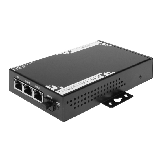
2. Specifications Transmitter Receiver HDMI Output HDMI (Female) HDMI (Female) Console Connectors RS-232 Control Port RJ-45 RJ-45 PC Connectors DisplayPort Input HDMI (Female) Extension Port RJ-45 Full HD Video 1080p / Audio Extension + IR + RS232 RJ-45 Ports 3 (Line In or Line Out) 3 (Line In or Line Out) Fiber Link Cascaded-Chainable... - Page 5 3. Det tail Pictu Trans smitter (T TX): 1. HD DMI IN: Con nnect to a HDMI sou urce by usin ng HDMI c cable 2. HD DMI OUT: L Local HDM MI output, c connect to a display m monitor by using HDM 3.
-
Page 6: Receiver(Rx)
Recei ver (RX) 1. HD DMI OUT: C Connect to o a display monitor by y using HD DMI cable 2. IR: IR receive er port, con nnect the I R receiver r cable to th his port (ple ease refer to append dix 2) 3. -
Page 7: Connection Diagram
4. Connection Diagram Broadcasting Model with one single source Broadcasting Model with multi source... -
Page 8: Video Wall Model With Single Source
Video Wall Model with single source Video Wall Model with multi source... - Page 9 5. Con ntrol sys stem setu up Prepa aration Conne ect contro ol PC to a any one o of the TX or RX as s below, t the whole broadc cast or vi ideo wall system i s an intra anet syste em, henc ce the con...
- Page 10 “Bonj jour SDK K” Install lation Enable e “Bonjou ur”, open the IE of f the cont trolling PC C , Route e: View -> > Explore Bars -> B Bonjour...
-
Page 11: Video Wall Setup Procedure
Video Wall setup procedure For every Video Wall setup, just only three key points as below need to be clarified. Monitor size detail, including monitor outside width (OW) and outside height (OH), inner viewable Width (VW) and viewable height (VH), this is for the Gap Compensation function. The OW, OH, VW, VH is a number or value with the unit based on every 0.1mm. -
Page 12: Example 1, 2 X 2 Video Wall Setting
Monitor Position, each monitor has its own row number and column number which represent its “Monitor Position” in its belonging Video Wall Group. Besides, these row and column number are started from 0, users can refer to below examples: Example 1, 2 X 2 Video Wall setting, please follow below setting procedures: Here we use monitor, Acer P246HL, as our model type. - Page 13 2. Double click any of the RX, then you can find the below chart, then click “Video Wall Setup” 3. Mark the “Show OSD” on the bottom, then you can see the OSD number showed on each display monitor, please be noted the OSD number is generated at random, not in order.
- Page 14 4. After then, we have to do the video wall setting one by one. There are four monitors in a 2x2 video wall group, which are the upper‐left, upper‐right, lower left and the lower right, user can find below structure chart: 5.
- Page 15 OW: 56 6.5cm = 56 65mm = 56 650 unit (th he unit is 0 .1mm) OH: 33 3.5cm = 33 35mm = 33 50 unit VW: 53 3.5cm = 53 35mm = 53 350 unit VH: 30 .0cm = 300 0mm = 300 00 unit Key in...
- Page 16 6. Now w we go to t the monito or upper‐rig ght, key in the monito or detail in the block” ” Bezel Gap Comp pensation” as below just like be efore: Next is the block “Wall Size e and Posit tion Layout t”, please f follow belo...
- Page 17 7. The monitor low w er‐left:...
- Page 18 8. The last one, m m onitor low wer‐right:...
-
Page 19: Example 2, 3 X 3 Video Wall With Single Hdmi Source Setting
Example 2, 3 X 3 Video Wall with single HDMI source setting, please follow below setting procedures: Before begin to the setting, we have to know the 3 X 3 video wall structure and each monitor’s position in the video wall group as below chart, and then we will do each monitor’s setting one by one. - Page 20 2. Double click any one of the “RX”, then click” Video Wall Setup” 3. Mark the “Show OSD” on the bottom, then you can see the OSD number showed on each display monitor, please be noted the OSD number is generated at random, not in sequence.
- Page 21 4. Then we first go to the Upper‐Left monitor with OSD number:7...
- Page 22 5. T The Upper r‐Middle m monitor with h OSD num mber 2: 6. T The Upper r‐Right mo onitor with OSD num ber: 6...
- Page 23 7. T The Middle e‐Left mon nitor with O OSD numb er: 8 8. T The Middle e‐Middle m monitor wit th OSD nu mber: 0...
- Page 24 9. T The Middle e‐Right mo onitor with OSD num mber: 3 10. T The Lower r‐Left mon nitor with O OSD numbe er: 5...
- Page 25 11. T The Lower r‐Middle m monitor with h OSD num mber: 1 Finally, the e Lower‐R Right with O OSD numb er: 4...
-
Page 26: Example 3, 2 X 4 Video Wall With 3 Hdmi Source Setting
Example 3, 2 X 4 Video Wall with 3 HDMI source setting, please follow below setting procedures: A 2 x 4 video wall group can be shaped with different combination, such as below examples. Example 1, 2X4 video wall is shaped from 1 of 2X2 video wall, and 2 of 1X2 video wall. Example 2, 2X4 video wall is shaped from 1 of 1X4 video wall, and 2 of 1X2 video wall. - Page 27 We now have 3 video groups: group 1, group 2, and group 3, we just set each video group one by one. Before we begin the set up, we have to know the hardware installation and connection please follow below hardware installation. As below diagram showed, the video wall group 1 displays the video from HDMI source 1, and the group 2 displays the video from source 2, and the group 3 displays the video from source 3.
- Page 28 After all the hardware is settle down, then we can begin to set up the video wall, please follow the below procedure step by step: 1. Open the IE of the control system, and key in http://ast‐gateway0000.local/, you will find the below picture:...
- Page 29 2. Double click any of the RX, and click “Video Wall Setup” 3. Mark the “Show OSD” on the bottom, then you can see the OSD number showed on each display monitor, please be noted the OSD number is generated at random, not in order. 4.
- Page 30 Monito r 1 of grou p 1 setting Monito r 2 of grou p 1setting:...
- Page 31 Monito r 3 of grou p 1 setting Monito r 4 of grou p 1 setting...
- Page 32 Group 2 video wall setting Monitor 1 of group 2 setting: Monitor 2 of group 2 setting:...
-
Page 33: Appendix 1: Reset Button
6. Group 3 video wall setting: Monitor 1 of group 3 setting: Monitor 2 of group 3 setting: Appendix 1: Reset button • Short press: Short press is for device reset when “LINK ID: changed, user just push “RESET” button when turning the LINK ID for changing display source. •... -
Page 34: Appendix 2: Ir Connection
Appen ndix 2: IR R Conne ection • C Connect th he IR blast ter cable to o the TX’s IR connec tor. • C Connect th he IR recei iver cable t to the RX’s s IR conne ector. •... - Page 35 • O Operating the contro ol system. • T The RS‐23 32 connec ction is bi‐d directional, , the device e and the c control sys stem are interch hangeable and Contr rol System is able to control the device at T TX or RX.
- Page 36 Hinweis: Bei falscher Installation und unsachgemäßem Gebrauch im Wohnbereich kann das Gerät Störungen bei Rundfunkgeräten und anderen elektronischen Geräten verursachen. Ein sachgemäßer Gebrauch liegt vor, wenn das Gerät, soweit durchführbar, mit geschirmten Anschlusskabeln betrieben wird (bei Netzwerkprodukten zusätzlich geschirmter Kabel der Kategorie 5e und höher). Das Gerät wurde getestet und liegt innerhalb der Grenzen für Computerzubehör der Klasse A gemäß...
Need help?
Do you have a question about the DS-55300 and is the answer not in the manual?
Questions and answers