Advertisement
INSTALLATION INSTRUCTIONS FOR PART 95-7510
95-7510/
95-7510HG
KIT FEATURES
• Double DIN Radio Provision
• Stacked ISO Mount Units Provision
• TWO FINISHES AVAILABLE:
99-7510=BLACK, 99-7510HG=GLOSS BLACK
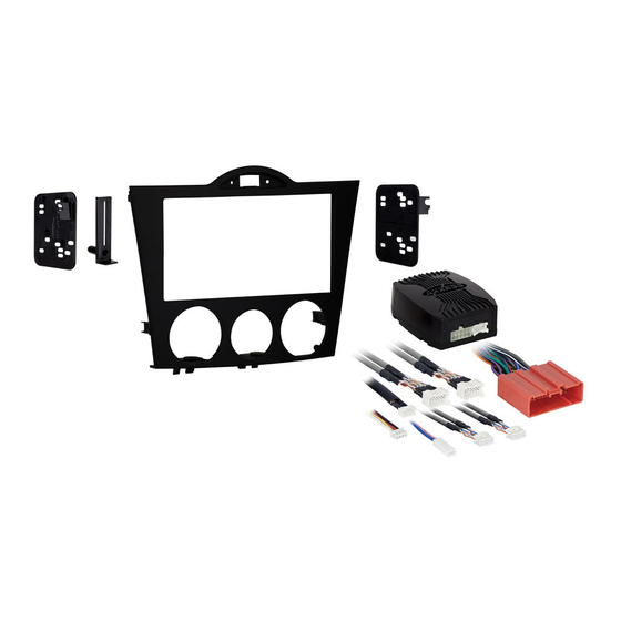
KIT COMPONENTS
• A) Radio / Climate Control Housing • B) Double DIN Radio Brackets • C) Rear Support
• D) Interface • E) Wiring Harnesses • F) (2) Climate Control Extension Harnesses
A
1-800-221-0932
© COPYRIGHT 2004-2008 METRA ELECTRONICS CORPORATION
APPLICATIONS
Mazda RX-8
2004-2008
B
E
TOOLS REQUIRED:
Small Flat Blade Screwdriver/ Panel Removal Tool
• Phillips Screwdriver • Socket Set • Cutting Tool
D
C
F
www.metraonline.com
Advertisement
Table of Contents

Summary of Contents for Metra Electronics 95-7510
- Page 1 INSTALLATION INSTRUCTIONS FOR PART 95-7510 Mazda RX-8 95-7510/ 95-7510HG KIT FEATURES • Double DIN Radio Provision • Stacked ISO Mount Units Provision • TWO FINISHES AVAILABLE: 99-7510=BLACK, 99-7510HG=GLOSS BLACK KIT COMPONENTS • A) Radio / Climate Control Housing • B) Double DIN Radio Brackets • C) Rear Support •...
-
Page 2: Table Of Contents
Display Customization ........7 *Note: Refer also to the instructions included with the aftermarket radio. 95-7510 NOWLEDGE IS Enhance your installation and fabrication skills by enrolling in the most recognized and respected mobile electronics school in our industry. -
Page 3: Mazda Rx-8 2004-2008
(Figure C) Unclip and remove the knee panel on the driver’s side under the steering column (Figure D) then remove (1) 10 MM bolt from the side of the radio bracket. (Figure E) Continued on page 2. 95-7510 DASH DISASSEMBL Y... -
Page 4: Kit Assembly
Remove (6) screws securing the cli- mate controls from the radio/climate control panel. Unplug and remove the climate controls. (Retain the screws and climate controls for re-use during kit assembly.) (Figure J) Continued on page 3. 95-7510 DASH DISASSEMBL Y... - Page 5 Remove (2) screws securing the haz- ard switch to the radio/climate control panel. Unplug and remove hazard switch. (Retain the screws and hazard switch for re-use during kit assem- bly.) (Figure L) Continue to kit assembly. 95-7510 DASH DISASSEMBL Y REMOVE (2) SCREWS PER SIDE...
-
Page 6: Double Din Radio Provision / Stacked Iso Mount Units Provision
Double DIN or stacked ISO Mount unit(s) using the hardware supplied with the unit(s). (Figure C) Attach the rear support to the unit(s) using the hardware supplied with the unit(s). (Figure D) Continue to final assembly. 95-7510 KIT ASSEMBL Y... -
Page 7: Final Assembly
*NOTE: When a Black wire is not present, ground radio to vehicle chassis. All colors may not be present on all leads due to manufacturer’s specifications. 95-7510 FINAL ASSEMBL Y (A) Strip wire ends back 1/2" B) Twist ends together... - Page 8 “DISP”. Plug the Hazard Switch extension cable into the end of the hazard switch and the other end of the extension cable into the port next to the “DISP” port. 95-7510 FINAL ASSEMBL Y WARNING! Continued on Page 7...
- Page 9 NOTE: Reverse output is NOT present on manual transmission vehicles. Re-connect the negative battery terminal and test the unit for proper operation. Reassemble radio and dash assemblies in reverse order of disassembly. 95-7510 FINAL ASSEMBL Y PINK WIRE 1 2 3 4 5 6 7 8...
-
Page 10: Display Customization
When you are finished entering your text if you do not press any buttons for 5 sec- onds the display will save and return to the default screen and the climate control buttons will return to their normal configuration. 95-7510 KIT ASSEMBL Y TILT OPEN... - Page 11 95-7510 NOTES...
- Page 12 95-7510 INSTRUCTIONS www.metraonline.com 1-800-221-0932 REV. 10/30/08 © COPYRIGHT 2004-2008 METRA ELECTRONICS CORPORATION INST95-7510...


Need help?
Do you have a question about the 95-7510 and is the answer not in the manual?
Questions and answers