Table of Contents
Advertisement
Quick Links
I n s t r u c t i o n M a n u a l
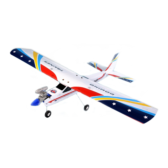
SIZE .46-.55 GP/EP SCALE 1:6 ARF
SPECIFICATION
- Wingspan: 1583mm (62.3in)
- Length: 1270mm (50 in)
- Flying weight: 2600-2800 gr
- Wing area: 44.3 dm2
- Wing loading: 65g/dm2
- Wing type: Naca airfoils
- Covering type: V-kote film
- Spinner size: Plastic 58mm (included)
- Radio: 4 channel minimum (not included)
- Servo: 5 standard servo: 2 aileron;
1 elevator; 1 rudder; 1 throttle (not included)
- Recommended receiver battery:
4.8-6V / 800-1200mAh NiMH (not included)
- Servo mount: 21mm x 42 mm
- Propeller: suit with your engine
- Engine: .40-.46 / 2-stroke (not included)
We wish you many enjoyable flights with your plane and one again thank you for your choosing a Phoenix Model products.
- Motor: brushless outrunner
- Gravity CG: 75-80 mm (2.9-3.1 in) Back from
the leading edge of the wing, at the fuselage
- Control throw Ailerons: Low: 8mm up/down,
10% expo; High: 10mm up/down, 10% expo
- Control throw Elevators: Low: 8mm up/down,
12% expo; High: 10mm up/down, 12% expo
- Control throw Rudder: Low: 25mm right/left,
15% expo; High: 40mm right/left, 15% expo
- Experience level: Beginer
- Plane type: Trainer
RECOMMENDED MOTOR AND BATTERY SET UP
- Motor: RIMFIRE .46 (not included)
- Lipo cell: 4-6 cells / 4000-5000 mAh (not included)
- Esc: 50-60A (not included)
Advertisement
Table of Contents

Related Manuals for Phoenix Model DOMINO

Summary of Contents for Phoenix Model DOMINO
- Page 1 - Lipo cell: 4-6 cells / 4000-5000 mAh (not included) - Propeller: suit with your engine - Engine: .40-.46 / 2-stroke (not included) - Esc: 50-60A (not included) We wish you many enjoyable flights with your plane and one again thank you for your choosing a Phoenix Model products.
-
Page 2: Table Of Contents
Thank you for purchasing Phoenix Model products. With over 20 years experience in production and fly testing, Phoenix Model is committed to bring the best quality products and good service to customers. Along with a team of creative engineers and skilled workers, we will always accompany with customers by our great experiences, fully enthusiasm... -
Page 3: Warranty
Vacuum the parts and the work area to assemble and use this. thoroughly after working with fiberglass parts. In that Phoenix Model has no control over the final assembly or material used for final assembly, Phoenix SUGGESTION Model is not responsible for loss of use , or other incidental or consequential damages. -
Page 4: Flight Warnings
Instruction Manual DOMINO FLIGHT WARNINGS ADHESIVES AND REQUIRED TOOLS When ready to fly, first extend the transmitter aerial. Thin CA Switch on the transmitter. 30-minute epoxy Switch on the receiver. 6-minute epoxy Check that the wings are correctly fitted to the Threadlocker thread locking cement fuselage. - Page 5 Instruction Manual DOMINO • Officially designated AMA Air Show Teams (AST) are authorized to use devices and practices as defined within the Team AMA Program Document. (AMA Document #718.) (j) Not operate a turbine-powered aircraft, unless in compliance with the AMA turbine regulations. (AMA Document #510-A.)
-
Page 6: Preparations
Instruction Manual DOMINO PREPARATIONS INSTALLING THE AILERONS servo and linkage Remove the tape and separate the ailerons from the wing and the elevators from the stab. Use a covering iron with a covering sock on high heat to tighten the covering if necessary. -
Page 7: Joining The Wing Halves
Instruction Manual DOMINO Bend “L” the metal pushrod. Install the control horn onto the aileron. Insert the nylon clasp to the metal rod. Make the same way for the second aileron servo. Joining the wing halves Cut away the metal rod. -
Page 8: Horizontal Stabilizer Installation
Instruction Manual DOMINO 2. Draw a center line onto the horizontal stabilizer. HORIZONTAL STABILIZER INSTALLATION 1. Using a modeling knife, cut away the covering from the fuselage for the stabilizer and remove it. 3. Check the fit of the horizontal stabilizer in its slot. -
Page 9: Installing The Rudder
Instruction Manual DOMINO Remove the covering Glue with epoxy 8. Glue the elevator to the horizontal stabilizer by C.A glue. C.A glue INSTALLING THE RUDDER Repeat step 1 - step 2 from the installing aileron for the installing rudder. 6. When you are sure that everything is aligned correctly, mix up a generous amount of 30 minute epoxy. -
Page 10: Installing The Elevator And Rudder Pushod
Instruction Manual DOMINO Glue the hinges by C.A glue Cut away screw. Remove the covering from the slot. INSTALLing the elevator and rudder Pushrod Attach the clevis to the elvator pushrod. The control horn. Insert the elevator pushrod into the fuselage. -
Page 11: Installing The Landing Gear
Instruction Manual DOMINO Insert the rudder pushrod into the fuselage. Attach the clevis to the control horn. Attach the clevis to the control horn. Make same way for the second elevator pushrod. INSTALLING THE LANDING GEAR Install the nylon control horn onto the rudder. -
Page 12: Installing The Servo Of The Rudder
Instruction Manual DOMINO Install the wheel. Remove the covering on the fuselage. INSTALLING THE SERVO OF THE RUDDER, THE ELEVATOR AND FUEL TANK. Secure the landing gear. Install the rudder servo. The nose gear. Install the metal connector. - Page 13 Instruction Manual DOMINO Cut and bend "L" the rudder pushrod. Install the elevator pushrod and secure it. Install the rudder and the nose gear pushrod. Install the elevator servo. Prepare the metal connector.
-
Page 14: Installing The Stopper
Instruction Manual DOMINO INSTALLING THE Stopper Cut off shaded portion... -
Page 15: Installing The Engine
Instruction Manual DOMINO Install the engine and secure it. Secure the stopper to the tank. Slide the fuel tank into the fuselage. Secure the muffer. 15 mm Finishing. Install the silicon tubes. INSTALLING THE engine Attach the throttle rod into the arm of the carburator. -
Page 16: Installing The Motor And Battery
Instruction Manual DOMINO INSTALLING THE MOTOR AND BATTERY Screw Installing the electric motor This model can fly with electric, here is our recommended for set up the system. - Motor brushless: Rimfire .46 - Lipo cells: 4-6 cells / 4000 - 5000 mAh. - Page 17 Instruction Manual DOMINO Install the metal connector. Install the throttle servo. Attach the throttle rod into the metal connector and secure it. Secure the servo arm. Cut away the throttle rod if neccessary. Low throttle stick position. Mid throttle stick position.
-
Page 18: Installing The Switch, Spinner And Propller
Instruction Manual DOMINO INSTALLING THE SWITCH, SPINNER AND PROPLLER. BALANCING Switch 1. It is critical that your airplane be balanced correctly. Improper balance will cause your plane to lose control and crash. THE CENTER OF GRAVITY IS LOCATED 75-80mm BACK FROM THE LEADING EDGE OF THE WING, AT THE FUSELAGE. -
Page 19: Flight Preparation Pre Flight Check
Instruction Manual DOMINO LOW RATE Ailerons : 8 mm up 8 mm down Elevator : 8mm up 8 mm down Rudder : 25 mm right 25 mm left HIGH RATE Ailerons : 10 mm up 10 mm down Elevator : 10mm up... - Page 20 I/C FLIGHT GUIDELINES Operate the control sticks on the When ready to fly, first extend the transmitter and check that the control transmitter aerial. surfaces move freely and in the ALWAYS land the model INTO the CORRECT directions. wind, this ensures that the model lands at the slowest possible speed.
Need help?
Do you have a question about the DOMINO and is the answer not in the manual?
Questions and answers