Table of Contents
Advertisement
Quick Links
Advertisement
Table of Contents

Related Manuals for DFI LR100-N16 Series


Summary of Contents for DFI LR100-N16 Series
- Page 1 LR100-N16/N18 SERIES System Board User’s Manual A12540350...
-
Page 2: Copyright
Copyright This publication contains information that is protected by copyright. No part of it may be reproduced in any form or by any means or used to make any transfor- mation/adaptation without the prior written permission from the copyright hold- ers. -
Page 3: Fcc And Doc Statement On Class B
FCC and DOC Statement on Class B This equipment has been tested and found to comply with the limits for a Class B digital device, pursuant to Part 15 of the FCC rules. These limits are designed to provide reasonable protection against harmful interference when the equipment is operated in a residential installation. -
Page 4: Table Of Contents
Introduction Table of Contents ................... 2 Copyright Trademarks ..................2 FCC and DOC Statement on Class B ..........3 ................6 About this Manual ..................6 Warranty Static Electricity Precautions ............. 7 ................. 7 Safety Measures ................8 About the Package Before Using the System Board ............ - Page 5 Introduction ................36 I/O Connectors CD-in Internal Audio Connector ..........36 S/PDIF Connector ..............37 LVDS LCD Panel Connector and LCD/Inverter Power Connector ..38 Digital I/O Connector ..............40 SATA (Serial ATA) Connectors ............ 41 IDE Connector ................. 42 Cooling Fan Connectors .............
-
Page 6: About This Manual
Introduction About this Manual An electronic file of this manual is included in the CD. To view the user’s manual in the CD, insert the CD into a CD-ROM drive. The autorun screen (Main Board Utility CD) will appear. Click “User’s Manual” on the main menu. Warranty 1. -
Page 7: Static Electricity Precautions
Introduction Static Electricity Precautions It is quite easy to inadvertently damage your PC, system board, components or devices even before installing them in your system unit. Static electrical dis- charge can damage computer components without causing any signs of physical damage. -
Page 8: About The Package
Introduction About the Package The system board package contains the following items. If any of these items are missing or damaged, please contact your dealer or sales representative for as- sistance. One system board One IDE cable One USB cable ... -
Page 9: Chapter 1 - Introduction
Introduction Chapter 1 - Introduction Specifications Processor • Intel Atom D510 (Dual Core) - LR100-N16D ® Intel Atom D410 (Single Core) - LR100-N16S ® Intel Atom N450 (Single Core) - LR100-N16M ® Intel Atom D525 (Dual Core) - LR100-N18D ® Intel Atom D425 (Single Core) - LR100-N18S... - Page 10 Introduction Graphics LR100-N16D/N16S/N18D/N18S • Intel GMA 3150 ® - Contains a refresh of the 3rd generation graphics core • 400MHz render clock frequency • Display ports: LVDS and RGB - Integrated single LVDS channel supports resolution up to 1366x768, 18bpp - Analog RGB display output up to resolution 2048x1536 @ 60Hz •...
- Page 11 Introduction I/O Connectors • 3 connectors for 6 external USB 2.0/1.1 ports • 1 connector for an external RS232/422/485 serial port • 1 LVDS LCD panel connector • 1 LCD/inverter power connector • 1 8-bit DIO connector • 1 DIO power connector •...
-
Page 12: Features
Introduction Features Watchdog Timer The Watchdog Timer function allows your application to regularly “clear” the sys- tem at the set time interval. If the system hangs or fails to function, it will reset at the set time interval so that your system will continue to operate. CompactFlash The system board is equipped with the CompactFlash socket for inserting a... - Page 13 Introduction Serial ATA Serial ATA is a storage interface that is compliant with SATA 1.0a specification. With speed of up to 3GB/s, it improves hard drive performance faster than the standard parallel ATA whose data transfer rate is 100MB/s. Gigabit LAN The Intel 82567V and Realtek RTL8111C PCI Express Gigabit controllers support up to 1Gbps data transmission.
-
Page 14: Chapter 2 - Hardware Installation
Hardware Installation Chapter 2 - Hardware Installation System Board Layout DDR2_2 SODIMM CPU fan PS/2 Mouse PS/2 KB COM2 RS232/Power select (J6) DDR2_1 SODIMM PS/2 power select (J COM 2 COM 1 LVDS LCD LCD/Inverter power panel Intel Power-on select ( COM 4 Panel power select (... -
Page 15: System Memory
Hardware Installation Important: Electrostatic discharge (ESD) can damage your system board, processor, disk drives, add-in boards, and other components. Perform the upgrade instruction procedures described at an ESD workstation only. If such a station is not available, you can provide some ESD protection by wearing an antistatic wrist strap and attaching it to a metal part of the system chassis. -
Page 16: Installing The Dim Module
Hardware Installation Installing the DIM Module Note: The system board used in the following illustrations may not resemble the actual one. These illustrations are for reference only. 1. Make sure the PC and all other peripheral devices connected to it has been powered down. - Page 17 Hardware Installation 5. Grasping the module by its edges, align the module into the socket at an ap- proximately 30 degrees angle. Apply firm even pressure to each end of the module until it slips down into the socket. The contact fingers on the edge of the module will almost completely disappear inside the socket.
-
Page 18: Jumper Settings
Hardware Installation Jumper Settings Clear CMOS Data 1-2 On: Normal (default) 2-3 On: Clear CMOS Data If you encounter the following, a) CMOS data becomes corrupted. b) You forgot the supervisor or user password. you can reconfigure the system with the default values stored in the ROM BIOS. To load the default values stored in the ROM BIOS, please follow the steps below. -
Page 19: Ps/2 Power Select
Hardware Installation PS/2 Power Select 2-3 On: 1-2 On: +5V (default) +5V_standby JP1 is used to select the power of the PS/2 keyboard/mouse port. Selecting +5V_standby will allow you to use the PS/2 keyboard or PS/2 mouse to wake up the system. -
Page 20: Usb Power Select
Hardware Installation USB Power Select USB 8-9 power select (JP4) USB 4-7 power select (JP3) 1-2 On: +5V 2-3 On: (default) +5V_standby USB 0-3 power select (JP2) JP2 (for USB 0-3), JP3 (for USB 4-7) and JP4 (for USB 8-9) are used to select the power of the USB ports. -
Page 21: Panel Power Select
Hardware Installation Panel Power Select 5 3 1 5 3 1 5 3 1 1-2 On: +12V 3-4 On: +5V 5-6 On: +3.3V (default) J5 is used to select the power supplied to the LCD panel. Important: Before powering-on the system, make sure J5’s setting matches the LCD panel’s specification. -
Page 22: Compactflash Card Setting
Hardware Installation CompactFlash Card Setting 1-2 On: Master 2-3 On: (default) Slave JP6 is used to set the CompactFlash card to Master or Slave mode. Note: We do not recommend using IDE devices and CF card at the same time. -
Page 23: Com 3 Rs232/Rs422/Rs485 Select
Hardware Installation COM 3 RS232/RS422/RS485 Select JP9 is used to configure COM 3 to RS232, RS422 (Half Duplex) or RS485. The pin function of COM 3 will vary according to the jumper’s setting. 1-2 On: RS232 3-4 On: RS422 5-6 On: RS485 (default) Half Duplex COM 3... -
Page 24: Com 2 Rs232/Power Select
Hardware Installation COM 2 RS232/Power Select 1-3, 2-4 On: 3-5 (+12V), RS232 standard 4-6 (+5V) On: (default) RS232 with power COM 2 1 2 3 4 5 1 2 3 4 5 6 7 8 9 6 7 8 9... -
Page 25: Power-On Select
Hardware Installation Power-on Select 1-2 On: Power-on via power button (default) 2-3 On: Power-on via AC power JP8 is used to select the method of powering on the system. If you want the system to power-on whenever AC power comes in, set JP8 pins 2 and 3 to On. If you want to use the power button, set pins 1 and 2 to On. -
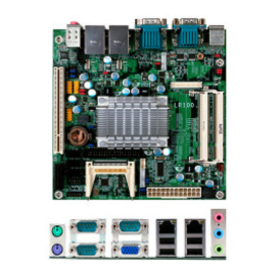
Page 26: Rear Panel I/O Ports
Hardware Installation Rear Panel I/O Ports PS/2 COM 2 COM 4 LAN 1 LAN 2 Mic-in Mouse Line-in Line-out PS/2 K/B USB 0-1 USB 2-3 COM 1 The rear panel I/O ports consist of the following: • PS/2 mouse port • PS/2 keyboard port • 3 COM ports • VGA port • 2 LAN ports • 4 USB ports •... -
Page 27: Ps/2 Mouse And Ps/2 Keyboard Ports
Hardware Installation PS/2 Mouse and PS/2 Keyboard Ports PS/2 Mouse PS/2 KB These ports are used to connect a PS/2 mouse and a PS/2 keyboard. The PS/2 mouse port uses IRQ12. If a mouse is not connected to this port, the system will reserve IRQ12 for other expansion cards. Important: Make sure to turn off your computer prior to connecting or disconnecting a mouse or keyboard. Failure to do so may damage the system board. Wake-On-PS/2 Keyboard/Mouse The Wake-On-PS/2 Keyboard/Mouse function allows you to use the PS/2 keyboard or PS/2 mouse to power-on the system. To use this function: • Jumper Setting JP1 must be set to “2-3 On: 5V_standby”. Refer to “PS/2 Power Select” in this chapter for more information. -
Page 28: Com (Serial) Ports
Hardware Installation COM (Serial) Ports COM 2 COM 1 COM 4 COM 3 1 2 3 4 5 6 7 8 9 COM 1, COM 2 and COM 4 COM 1, COM 2 and COM 4 are fixed at RS232. COM 3’s pin definition will vary according to JP9’s settings. Refer to “COM 3 RS232/RS422/RS485 Select” in this chapter for more information. The serial ports are asynchronous communication ports with 16C550A-compatible UARTs that can be used with modems, serial printers, remote display terminals, and other serial devices. -
Page 29: Hardware Installation
Hardware Installation Connecting External Serial Ports Your COM port may come mounted on a card-edge bracket. Install the card-edge bracket to an available slot at the rear of the system chassis then insert the se- rial port cable to the COM connector. Make sure the colored stripe on the ribbon cable is aligned with pin 1 of the COM connector. BIOS Setting Configure the serial ports in the Advanced menu (“Super IO Configuration” sub- menu) of the BIOS. Refer to chapter 3 for more information. -
Page 30: Vga Port
Hardware Installation VGA Port The VGA port is used for connecting a VGA monitor. Connect the monitor’s 15-pin D-shell cable connector to the VGA port. After you plug the monitor’s cable con- nector into the VGA port, gently tighten the cable screws to hold the connector in place. BIOS Setting Configure the onboard VGA in the Chipset menu of the BIOS. Refer to chapter 3 for more information. -
Page 31: Rj45 Lan Ports
Hardware Installation RJ45 LAN Ports LAN 1 LAN 2 The LAN ports allow the system board to connect to a local area network by means of a network hub. BIOS Setting Configure the onboard LAN ports in the Chipset menu (“South Bridge Chipset Configuration” submenu) of the BIOS. Refer to chapter 3 for more information. Driver Installation Install the LAN drivers. Refer to chapter 4 for more information. -
Page 32: Usb Ports
Hardware Installation USB Ports USB 1 USB 0 USB 3 USB 4-5 USB 2 USB 6-7 USB 8-9 USB allows data exchange between your computer and a wide range of simulta- neously accessible external Plug and Play peripherals. The system board is equipped with four onboard USB 2.0/1.1 ports. The three 10-pin connectors allow you to connect 6 additional USB 2.0/1.1 ports. The USB ports may be mounted on a card-edge bracket. Install the card-edge bracket to an available slot at the rear of the system chassis then insert the USB port cables to a connector. - Page 33 Hardware Installation Wake-On-USB Keyboard/Mouse The Wake-On-USB Keyboard/Mouse function allows you to use a USB keyboard or USB mouse to wake up a system from the S3 (STR - Suspend To RAM) state. To use this function: • Jumper Setting JP2, JP3 and/or JP4 must be set to “2-3 On: 5V_standby”. Refer to “USB Power Select” in this chapter for more information. •...
-
Page 34: Audio
Hardware Installation Audio Rear audio Mic-in Line-in Line-out Front audio Rear Audio The system board is equipped with 3 audio jacks. A jack is a one-hole connecting interface for inserting a plug. • Mic-in Jack (Pink) This jack is used to connect an external microphone. • Line-in Jack (Light Blue) This jack is used to connect any audio devices such as Hi-fi set, CD player, tape player, AM/FM radio tuner, synthesizer, etc. • Line-out Jack (Lime) This jack is used to connect a headphone or external speakers. Front Audio The front audio connector allows you to connect to the second line-out and mic- in jacks that are at the front panel of your system. - Page 35 Hardware Installation BIOS Setting Configure the onboard audio in the Chipset menu (“South Bridge Chipset Configu- ration” submenu) of the BIOS. Refer to chapter 3 for more information. Driver Installation Install the audio driver. Refer to chapter 4 for more information.
-
Page 36: I/O Connectors
Hardware Installation I/O Connectors CD-in Internal Audio Connector Ground Ground Right audio Left audio channel channel The CD-in connector is used to receive audio from a CD-ROM drive, TV tuner or MPEG card. -
Page 37: S/Pdif Connector
Hardware Installation S/PDIF Connector SPDIF out Ground SPDIF in The S/PDIF connector is used to connect an external S/PDIF port. Your S/PDIF port may be mounted on a card-edge bracket. Install the card-edge bracket to an available slot at the rear of the system chassis then connect the audio cable to the S/PDIF connector. Make sure pin 1 of the audio cable is aligned with pin 1 of the S/PDIF connector. -
Page 38: Lvds Lcd Panel Connector And Lcd/Inverter Power Connector
Hardware Installation LVDS LCD Panel Connector LCD/Inverter Power Connector LVDS LCD panel LCD/Inverter power The system board allows you to connect a LCD Display Panel by means of the LVDS LCD panel connector and the LCD/Inverter power connector. These connec- tors transmit video signals and power from the system board to the LCD Display Panel. - Page 39 Hardware Installation LVDS LCD Panel Connector Pins Pins Function Function N. C. N. C. N. C. N. C. LVDS_Out2+ N. C. LVDS_Out2- N. C. LVDS_Out1+ N. C. LVDS_Out1- N. C. LVDS_Out0+ N. C. LVDS_Out0- N. C. LVDS_CLK1+ N. C. LVDS_CLK1- N. C. LVDS_DDCCLK N. C. LVDS_DDCDAA N. C. Panel Power Panel Power Panel Power Panel Power LCD/Inverter Power Connector Pins Function Panel Inverter Brightness Voltage Control...
-
Page 40: Digital I/O Connector
Hardware Installation Digital I/O Connector Digital I/O connector +12V Ground 5VSB Digital I/O power connector The Digital I/O connector provides powering-on function to an external device that is connected to this connector. Digital I/O Connector Pins Function DIO0 DIO1 DIO2 DIO3 DIO4 DIO5 DIO6 DIO7... -
Page 41: Sata (Serial Ata) Connectors
Hardware Installation SATA (Serial ATA) Connectors SATA 0 SATA 2 SATA 1 The Serial ATA connectors are used to connect Serial ATA devices. Connect one end of the Serial ATA cable to a SATA connector and the other end to your Serial ATA device. BIOS Setting Configure the Serial ATA drives in the Advanced menu (“IDE Configuration” sub- menu) of the BIOS. Refer to chapter 3 for more information. -
Page 42: Ide Connector
Hardware Installation IDE Connector Important: We do not recommend using IDE devices and CF card at the same time. The IDE connector is used to connect hard drives. The connector on the IDE cable can be inserted into this connector only if pin 1 of the cable is aligned with pin 1 of this connector. The IDE connector supports 2 devices, a Master and a Slave. Use an IDE ribbon cable to connect the drives to the system board. An IDE ribbon cable have 3 connectors on them, one that plugs into the IDE connector on the system board and the other 2 connects to IDE devices. The connector at the end of the cable is for the Master drive and the connector in the middle of the cable is for the Slave... - Page 43 Hardware Installation Important: If you encountered problems while using an ATAPI CD-ROM drive that is set in Master mode, please set the CD-ROM drive to Slave mode. Some ATAPI CD-ROMs may not be recognized and cannot be used if incorrectly set in Master mode. BIOS Setting Configure the onboard IDE in the Advanced menu (“IDE Configuration” submenu) of the BIOS. Refer to chapter 3 for more information.
-
Page 44: Cooling Fan Connectors
Hardware Installation Cooling Fan Connectors Ground Sense Power CPU fan Sense Power Ground System fan The fan connectors are used to connect cooling fans. The cooling fans will provide adequate airflow throughout the chassis to prevent overheating the CPU and sys- tem board components. BIOS Setting The Advanced menu (“Hardware Health Configuration” submenu) of the BIOS will display the current speed of the cooling fan. Refer to chapter 3 for more informa- tion. -
Page 45: Chassis Instrusion Connector
Hardware Installation Chassis Instrusion Connector Ground Chassis signal The board supports the chassis intrusion detection function. Connect the chas- sis intrusion sensor cable from the chassis to this connector. When the system’s power is on and a chassis intrusion occurred, an alarm will sound. When the system’s power is off and a chassis intrusion occurred, the alarm will sound only when the system restarts. -
Page 46: Power Connector
Hardware Installation Power Connector 12 24 +3.3VDC +12VDC +5VDC +5VDC +12VDC +5VDC +5VSB PWR_OK +5VDC +5VDC PS_ON# -12VDC +3.3VDC +3.3VDC +3.3VDC Connect a 24-pin ATX main power connector from the power supply unit to the 24-pin power connector. The connector from the power supply unit is designed to fit the 24-pin connector in only one orientation. Make sure to find the proper ori- entation before plugging the connector. The system board requires a minimum of 120 Watt power supply to operate. We recommend that you use a power supply that complies with the ATX12V Power Supply Design Guide Version 1.1. -
Page 47: Standby Led
Hardware Installation Standby LED Standby This LED will lit red when the system is in the standby mode. It indicates that there is power on the system board. Power-off the PC then unplug the power cord prior to installing any devices. Failure to do so will cause severe damage to the motherboard and components. -
Page 48: Front Panel Connectors
Hardware Installation Front Panel Connectors PWR-LED HDD-LED PWR-BTN RESET-SW HDD-LED - HDD LED This LED will light when the hard drive is being accessed. RESET SW - Reset Switch This switch allows you to reboot without having to power off the system. PWR-BTN - Power Switch This switch is used to power on or off the system. PWR-LED - Power/Standby LED When the system’s power is on, this LED will light. When the system is in the S1 (POS - Power On Suspend) state, it will blink every second. When the system is in the S3 (STR - Suspend To RAM) state, it will blink every 4 seconds. -
Page 49: Expansion Slots
Hardware Installation Expansion Slots PCI Express x1 PCI Express x1 Install PCI Express cards such as network cards or other cards that comply to the PCI Express specifications into the PCI Express x1 slot. PCI Slot The PCI slot supports expansion cards that comply with PCI specifications. You can install a PCI expansion card or a customized riser card designed for 1, 2 or 3 PCI slots expansion (for low profile PCI card only) into the PCI slot. -
Page 50: Battery
Hardware Installation Battery Battery The lithium ion battery powers the real-time clock and CMOS memory. It is an auxiliary source of power when the main power is shut off. Safety Measures • Danger of explosion if battery incorrectly replaced. • Replace only with the same or equivalent type recommend by the manufac- turer. • Dispose of used batteries according to local ordinance. -
Page 51: Compactflash Socket
Hardware Installation CompactFlash Socket CompactFlash socket The CompactFlash socket is used for inserting a CompactFlash card. Compact- Flash card is a small removable mass storage device designed with flash tech- nology - a non-volatile storage solution that does not require a battery to retain data indefinitely. The CompactFlash technology is widely used in products such as portable and desktop computers, digital cameras, handheld data collection scanners, PDAs, Pocket PCs, handy terminals and personal communicators. -
Page 52: Chapter 3 - Bios Setup
BIOS Setup Chapter 3 - BIOS Setup Overview The BIOS is a program that takes care of the basic level of communication be- tween the CPU and peripherals. It contains codes for various advanced features found in this system board. The BIOS allows you to configure the system and save the configuration in a battery-backed CMOS so that the data retains even when the power is off. - Page 53 BIOS Setup Legends Keys Function Right and Left arrows Moves the highlight left or right to select a menu. Up and Down arrows Moves the highlight up or down between submenus or fields. <Esc> Exits to the BIOS Setup Utility. + (plus key) Scrolls forward through the values or options of the highlighted field.
-
Page 54: Ami Bios Setup Utility
BIOS Setup AMI BIOS Setup Utility Main The Main menu is the first screen that you will see when you enter the BIOS Setup Utility. BIOS SETUP UTILITY Main Advanced PCIPnP Boot Security Chipset Exit System Overview Use [ENTER], [TAB] or [SHIFT-TAB] to AMIBIOS select a field. -
Page 55: Advanced
BIOS Setup Advanced The Advanced menu allows you to configure your system for basic operation. Some entries are defaults required by the system board, while others, if enabled, will improve the performance of your system or let you set some features ac- cording to your preference. -
Page 56: Cpu Configuration
BIOS Setup CPU Configuration This section is used to configure the CPU. It will also display the detected CPU information. BIOS SETUP UTILITY Advanced Disabled for WindowXP Configure advanced CPU settings Module Version:3F.1C Manufacturer : Intel Intel(R) Atom(TM) CPU D455 @ 1.66GHz Frequency : 1.66GHz... -
Page 57: Bios Setup
BIOS Setup IDE Configuration This section is used to configure the IDE drives. BIOS SETUP UTILITY Advanced IDE Configuration Options [Enhanced] ATA/IDE Configuration Disabled [IDE] Configure SATA as Compatible Enhanced Primary IDE Master : [Not Detected] Primary IDE Slave : [Not Detected] ... - Page 58 BIOS Setup Primary IDE Master to Third IDE Slave When you enter the BIOS Setup Utility, the BIOS will auto detect the existing IDE devices then displays the status of the detected devices. To configure an IDE drive, move the cursor to a field then press <Enter>. BIOS SETUP UTILITY Advanced Select the type...
- Page 59 BIOS Setup PIO Mode Selects the data transfer mode. PIO means Programmed Input/Output. Rath- er than have the BIOS issue a series of commands to effect a transfer to or from the disk drive, PIO allows the BIOS to tell the controller what it wants and then let the controller and the CPU perform the complete task by them- selves.
-
Page 60: Super Io Configuration
BIOS Setup Super IO Configuration This section is used to configure the I/O functions supported by the onboard Super I/O chip. BIOS SETUP UTILITY Advanced Configure Super IO Chipset Allows BIOS to select Serial Port 1 base address. [3F8] Serial Port1 Address Serial Port1 IRQ Serial Port2 Address [2F8]... - Page 61 BIOS Setup PWRON After PWR-Fail When power returns after an AC power failure, the system’s power is off. You must press the Power button to power-on the system. When power returns after an AC power failure, the system will automatically power-on.
-
Page 62: Hardware Health Configuration
BIOS Setup Hardware Health Configuration This section is used to configure the hardware monitor function. BIOS SETUP UTILITY Advanced Enabled for Case Open Hardware Health Configuration Detection. If Case is open, system will show C/96 System Temperature warning message and beep C/120 CPU Temperature warning. -
Page 63: Acpi Configuration
BIOS Setup ACPI Configuration This section is used to configure ACPI. BIOS SETUP UTILITY Advanced ACPI Settings General ACPI configuration settings General ACPI Configuration Advanced ACPI Configuration Chipset ACPI Configuration Select Screen ← → Select Item ↑↓ Enter Go to Sub Screen General Help... -
Page 64: Advanced Acpi Configuration
BIOS Setup Advanced ACPI Configuration Configures additional ACPI functions. BIOS SETUP UTILITY Advanced Advanced ACPI Configuration Enable RSDP pointers to 64-bit Fixed System ACPI Version Features Description Tables. [ACPI v3.0] Different ACPI version has some addition. Select Screen ← → Select Item ↑↓... -
Page 65: Chipset Acpi Configuration
BIOS Setup Chipset ACPI Configuration Configures relevant chipset ACPI functions. BIOS SETUP UTILITY Advanced South Bridge ACPI Configuration Enable/Disable APIC ACPI SCI IRQ. APIC ACPI SCI IRQ [Disabled] USB Device Wakeup From S3 [Disabled] Select Screen ← → Select Item ↑↓... -
Page 66: Ahci Configuration
BIOS Setup AHCI Configuration This section is used to configure AHCI. BIOS SETUP UTILITY Advanced AHCI Settings While entering setup, BIOS auto detects the AHCI Port0 [Not Detected] presence of IDE devices. AHCI Port1 [Not Detected] This displays the status ... - Page 67 BIOS Setup AHCI Port0 to AHCI Port2 Configures the AHCI port. BIOS SETUP UTILITY Advanced AHCI Port0 Select the type of device connected Device :Not Detected to the system. SATA Port0 [Auto] S.M.A.R.T. [Enabled] Select Screen ← → Select Item ↑↓...
-
Page 68: Usb Configuration
BIOS Setup USB Configuration This section is used to configure USB devices. BIOS SETUP UTILITY Advanced USB Configuration Enables support for legacy USB. AUTO Module Version - 2.24.5-14.4 option disables legacy support if USB Devices Enabled : no USB devices are None connected. -
Page 69: Pcipnp
BIOS Setup PCIPnP The PCIPnP menu is used to configure PCI Plug and Play devices. Important: Setting incorrect field values may cause the system to malfunction. BIOS SETUP UTILITY Main Advanced PCIPnP Boot Security Chipset Exit Advanced PCI/PnP Settings Clear NVRAM during System Boot. -
Page 70: Boot
BIOS Setup Boot BIOS SETUP UTILITY Main Advanced PCIPnP Boot Security Chipset Exit Boot Settings Configure settings during system boot. Boot Settings Configuration Boot Device Priority Select Screen ← → Select Item ↑↓ Enter Go to Sub Screen General Help Save and Exit Exit... - Page 71 BIOS Setup Full Screen Logo Display This field is applicable only if you want a particular logo to appear during system boot-up. Enabled Displays OEM logo instead of the POST messages. Disabled Displays normal POST messages. Bootup Num-Lock This allows you to determine the default state of the numeric keypad. By default, the system boots up with NumLock on wherein the function of the numeric keypad is the number keys.
-
Page 72: Boot Device Priority
BIOS Setup Boot Device Priority This section is used to select the boot priority sequence of the devices. BIOS SETUP UTILITY Boot Boot Device Priority Specifies the boot sequence from the 1st Boot Device [Network: Realtek PX] available devices. 2nd Boot Device [Network: IBA GE Slo] A device enclosed in parenthesis has been... -
Page 73: Security
BIOS Setup Security BIOS SETUP UTILITY Main Advanced PCIPnP Boot Security Chipset Exit Security Settings Install or Change the password. Supervisor Password : Not Installed User Password : Not Installed Change Supervisor Password Change User Password Select Screen ← → Select Item ↑↓... - Page 74 BIOS Setup 3. Press <Enter> to confirm the new password. 4. When the Password Installed dialog box appears, select OK. To change the password, repeat the same steps above. To clear the password, select Change Supervisor Password then press <Enter>. The Password Uninstalled dialog box will appear.
-
Page 75: Change User Password
BIOS Setup Change User Password This field is used to set or change the user password. To set a new password: 1. Select the Change User Password field then press <Enter>. 2. Type your password in the dialog box then press <Enter>. You are limited to eight letters/numbers. - Page 76 BIOS Setup Boot Sector Virus Protection Enables or disables the boot sector virus protection function.
-
Page 77: Chipset
BIOS Setup Chipset This section is used to configure the system based on the specific features of the chipset. Important: Setting incorrect field values may cause the system to malfunction. BIOS SETUP UTILITY Main Advanced PCIPnP Boot Security Chipset Exit Advanced Chipset Settings Configure North Bridge features. - Page 78 BIOS Setup Initiate Graphics Adapter Selects the graphics controller to use as the primary boot device. Internal Graphics Mode Select Selects the amount of system memory used by the internal graphics device.
- Page 79 BIOS Setup Video Function Configuration BIOS SETUP UTILITY Chipset Video Function Configuration Options Fixed Mode DVMT Mode Select [DVMT Mode] DVMT/FIXED Memory [256MB] DVMT Mode Boot Display Device [VBIOS-Default] Flat Panel Type [3 :1024x768, 18bit] Select Screen ← → Select Item ↑↓...
-
Page 80: South Bridge Configuration
BIOS Setup South Bridge Configuration BIOS SETUP UTILITY Chipset South Bridge Chipset Configuration Options USB Functions [10 USB Ports] Disabled USB 2.0 Controller [Enabled] 2 USB Ports GbE Controller [Enabled] 4 USB Ports GbE LAN Boot [Disabled] 6 USB Ports GbE Wake Up From S5 [Disabled] 8 USB Ports... - Page 81 BIOS Setup HDA Controller Enables or disables the High Definition audio controller. PCIE1 Port Enables or disables the PCIE x1 slot. Onboard LAN Enables or disables the Realtek LAN controller.
-
Page 82: Exit
BIOS Setup Exit BIOS SETUP UTILITY Main Advanced PCIPnP Boot Security Chipset Exit Exit system setup Exit Options after saving the Save Changes and Exit changes. Discard Changes and Exit Discard Changes F10 key can be used for this operation. Load Optimal Defaults Load Failsafe Defaults Select Screen... -
Page 83: Discard Changes And Exit
BIOS Setup Discard Changes and Exit To exit the Setup utility without saving the changes, select this field then press <Enter>. A dialog box will appear. Confirm by selecting OK. You can also press <ESC> to exit without saving the changes. BIOS SETUP UTILITY Main Advanced... -
Page 84: Load Optimal Defaults
BIOS Setup Load Optimal Defaults To load optimal default values from the BIOS ROM, select this field then press <Enter>. A dialog box will appear. Confirm by selecting OK. You can also press <F9> to load optimal default values. BIOS SETUP UTILITY Main Advanced PCIPnP... -
Page 85: Updating The Bios
BIOS Setup Updating the BIOS To update the BIOS, you will need the new BIOS file and a flash utility, AFUDOS. EXE. Please contact technical support or your sales representative for the files. To execute the utility, type: A:> AFUDOS BIOS_File_Name /b /p /n /c then press <Enter>. -
Page 86: Chapter 4 - Supported Software
Supported Software Chapter 4 - Supported Software The CD that came with the system board contains drivers, utilities and software applications required to enhance the performance of the system board. Insert the CD into a CD-ROM drive. The autorun screen (Mainboard Utility CD) will appear. -
Page 87: Intel Chipset Software Installation Utility
Supported Software Intel Chipset Software Installation Utility The Intel Chipset Software Installation Utility is used for updating Windows files so that the Intel chipset can be recognized and configured properly in the system. To install the utility, click “Intel Chipset Software Installation Utility” on the main menu. - Page 88 Supported Software 3. Go through the readme document for more installa- tion tips then click Next. 4. After all setup operations are done, click Next. 5. Click Finish to exit setup.
-
Page 89: Intel Graphics Drivers
Supported Software Intel Graphics Drivers To install the driver, click “Intel Graphics Drivers” on the main menu. 1. Setup is ready to install the graphics driver. Click Next. 2. Read the license agreement then click Yes. 3. Go through the readme document for more installa- tion tips then click Next. - Page 90 Supported Software 4. Setup is currently installing the driver. After installation has completed, click Next. 5. Click “Yes, I want to restart this computer now.” then click Finish. Restarting the system will allow the new software in- stalllation to take effect.
-
Page 91: Audio Drivers
Supported Software Audio Drivers To install the driver, click “Audio Drivers” on the main menu. 1. Setup is ready to install the driver. Click Next. 2. Click “Yes, I want to restart my computer now” then click Finish. Restarting the system will allow the new software in- stallation to take effect. -
Page 92: Realtek Lan Drivers
Supported Software Realtek LAN Drivers To install the driver, click “Realtek LAN Drivers” on the main menu. 1. Setup is ready to install the driver. Click Next. 2. Click Install to begin the installation. 3. After completing installa- tion, click Finish. -
Page 93: Intel Lan Drivers
Supported Software Intel LAN Drivers To install the driver, click “Intel LAN Drivers” on the main menu. 1. Setup is ready to install the driver. Click Next. 2. Click “I accept the terms in the license agreement” then click “Next”. 3. - Page 94 Supported Software 4. Click Install to begin the installation. 5. After completing installa- tion, click Finish.
-
Page 95: Hardware Monitor For Windows
Supported Software Hardware Monitor for Windows The Hardware Monitor for Windows utility is capable of monitoring the system’s temperature, fan speed, voltage, etc. and allows you to manually set a range (Highest and Lowest Limit) to the items being monitored. If the settings/values are over or under the set range, a warning message will pop-up. - Page 96 Supported Software 3. Click Install to begin the installation. 4. After completing installa- tion, click Finish.
-
Page 97: Intel Matrix Storage Manager Utility
Supported Software Intel Matrix Storage Manager Utility Intel Matrix Storage Manager is a utility that allows you to monitor the current status of the SATA drives. It enables enhanced performance and power manage- ment for the storage subsystem. To install, click “Intel Matrix Storage Manager Utility” on the main menu. 1. - Page 98 Supported Software 3. Read the license agree- ment then click Yes. 4. Go through the readme document to view system requirements and installa- tion information then click Next. 5. Click “Yes, I want to restart my computer now” then click Finish.
-
Page 99: Ahci For F6 During Windows Setup Floppy Driver
Supported Software AHCI for F6 During Windows Setup Floppy Driver This is used to create a floppy driver diskette needed when you install Windows ® XP using the F6 installation method. This will allow you to install the operating system onto a hard drive when in AHCI mode. 1. - Page 100 Supported Software Infineon TPM Driver To install, click “Infineon TPM Driver” on the main menu. 1. The setup program is pre- paring to install the driver. 2. The driver has been suc- cessfully installed. Click Finish.
- Page 101 Supported Software Infineon TPM Utility To install, click “Infineon TPM Utility” on the main menu. 1. TPM requires installing the Microsoft Visual C++ pack- age prior to installing the utility. Click Install. 2. The setup program is cur- rently installing the Micro- soft Visual C++ package.
- Page 102 Supported Software 4. Click “I accept the terms in the license agreement” and then click “Next”. 5. Enter the necessary infor- mation and then click Next. 6. Select a setup type and then click Next.
- Page 103 Supported Software 7. Click Install. 8. Click Finish.
- Page 104 Supported Software Microsoft DirectX 9.0C Driver To install, click “Microsoft DirectX 9.0C Driver” on the main menu. 1. Click “I accept the agree- ment” then click Next. 2. You are now ready to install DirectX. Click Next. 3. Click Finish. Reboot the system for DirectX to take effect.
-
Page 105: Adobe Acrobat Reader
Supported Software Adobe Acrobat Reader 9.3 To install the reader, click “Adobe Acrobat Reader 9.3” on the main menu. 1. Click Next to install or click Change Destination Folder to select another folder. 2. Click Install to begin instal- lation. - Page 106 Supported Software 3. Click Finish to exit installa- tion.
-
Page 107: Appendix A - Nlite And Ahci Installation Guide
NLITE and AHCI Installation Guide Appendix A - NLITE and AHCI Installation Guide nLite nLite is an application program that allows you to customize your XP installation disc by integrating the RAID/AHCI drivers into the disc. By using nLite, the F6 function key usually required during installation is no longer needed. - Page 108 NLITE and AHCI Installation Guide 4. Insert the XP installation disc into an optical drive. 5. Launch nLite. The Welcome screen will appear. Click Next. 6. Click Next to temporarily save the Windows installa- tion files to the designated default folder. If you want to save them in another folder, click Browse, select the folder...
- Page 109 NLITE and AHCI Installation Guide 7. Click Next. 8. In the Task Selection dia- log box, click Drivers and Bootable ISO. Click Next.
- Page 110 NLITE and AHCI Installation Guide 9. Click Insert and then se- lect Multiple driver folder to select the drivers you will integrate. Click Next. Select only the drivers appropriate for the Win- dows version that you are using and then click OK. Integrating 64-bit driv- ers into 32-bit Windows or vice versa will cause...
- Page 111 NLITE and AHCI Installation Guide If you are uncertain of the southbridge chip used on your motherboard, select all RAID/AHCI con- trollers and then click Click Next.
- Page 112 NLITE and AHCI Installation Guide The program is currently integrating the drivers and applying changes to the installation. 14. When the program is fin- ished applying the chang- es, click Next.
- Page 113 NLITE and AHCI Installation Guide To create an image, se- lect the Create Image mode under the General section and then click Next. 16. Or you can choose to burn it directly to a disc by selecting the Direct Burn mode under the General section.
- Page 114 NLITE and AHCI Installation Guide You have finished cus- tomizing the Windows XP installation disc. Click Finish. Enter the BIOS utility to configure the SATA con- troller to RAID/AHCI. You can now install Windows...
- Page 115 NLITE and AHCI Installation Guide AHCI The installation steps below will guide you in configuring your SATA drive to AHCI mode. 1. Enter the BIOS utility and configure the SATA controller to IDE mode. 2. Install Windows XP but do not press F6. 3. Download relevant RAID/AHCI driver files supported by the motherboard chipset from Intel’s website. Transfer the downloaded driver files to C:\AHCI. 4. Open Device Manager and right click on one of the Intel Serial ATA Storage Controllers, then select...
- Page 116 NLITE and AHCI Installation Guide 5. In the Hardware Update Wizard dialog box, select “No, not this time” then click Next. 6. Select “Install from a list or specific location (Ad- vanced)” and then click Next. 7. Select “Don’t search. I will choose the driver to install”...
- Page 117 NLITE and AHCI Installation Guide 8. Click “Have Disk”. 9. Select C:\AHCI\iaAHCI.inf and then click Open. Select the appropriate AHCI Controller of your hardware device and then click Next.
- Page 118 NLITE and AHCI Installation Guide A warning message ap- peared because the se- lected SATA controller did not match your hardware device. Ignore the warning and click Yes to proceed. Click Finish. The system’s settings have been changed. Win- dows XP requires that you restart the computer.
-
Page 119: Appendix B - Watchdog Timer
Watchdog Timer Appendix B - Watchdog Timer Watchdog Timer The following parameters are references for setting the time interval of the Watchdog Timer function. The system will regularly be “cleared” according to the set time interval. If the system hangs or fails to function, it will also reset ac- cording to the time interval so that your system will continue to operate. - Page 120 Watchdog Timer NEWIODELAY dx, SuperIo_DAT_Port al, dx NEWIODELAY endM mSuperio_LDN_Select Macro mSuperio_Set_Reg 07h, LDN endM mSuperio_Set_Reg Macro RegIndex, SetValue dx, SuperIo_CFG_Port al, RegIndex dx, al NEWIODELAY dx, SuperIo_DAT_Port al, SetValue dx, al NEWIODELAY endM NEWIODELAY Macro 0EBh, al ;Dummy I/O output for delay endM .code start:...
- Page 121 Watchdog Timer ; PLED mode register, WDTO time unit as second, Keyboard reset when WDTO time out mSuperio_GetSet_Reg 0F5h, 11110111b, 00000100b ; , Disable MS/KB interrupt reset WDTO counting, IRQ2 for WDTO mSuperio_GetSet_Reg 0F7h, 11111111b, 11000010b ; , WDTO Time out Value mSuperio_Set_Reg 0F6h, WDT_Counter mSuperio_Exit_Config W83627Hx_WDT...
-
Page 122: Appendix C - System Error Message
System Error Message Appendix C - System Error Message When the BIOS encounters an error that requires the user to correct something, either a beep code will sound or a message will be displayed in a box in the mid- dle of the screen and the message, PRESS F1 TO CONTINUE, CTRL-ALT-ESC or DEL TO ENTER SETUP, will be shown in the information box at the bottom. - Page 123 System Error Message Hard Disk(s) fail (20) HDD initialization error. Hard Disk(s) fail (10) Unable to recalibrate fixed disk. Hard Disk(s) fail (08) Sector Verify failed. Keyboard is locked out - Unlock the key The BIOS detects that the keyboard is locked. Keyboard controller is pulled low. Keyboard error or no keyboard present Cannot initialize the keyboard.
-
Page 124: Appendix D - Troubleshooting
Troubleshooting Appendix D - Troubleshooting Troubleshooting Checklist This chapter of the manual is designed to help you with problems that you may encounter with your personal computer. To efficiently troubleshoot your system, treat each problem individually. This is to ensure an accurate diagnosis of the problem in case a problem has multiple causes. -
Page 125: Power Supply
Troubleshooting The picture seems to be constantly moving. 1. The monitor has lost its vertical sync. Adjust the monitor’s vertical sync. 2. Move away any objects, such as another monitor or fan, that may be creating a magnetic field around the display. 3. -
Page 126: Serial Port
Troubleshooting Serial Port The serial device (modem, printer) doesn’t output anything or is out- putting garbled characters. 1. Make sure that the serial device’s power is turned on and that the device is on-line. 2. Verify that the device is plugged into the correct serial port on the rear of the computer.
Need help?
Do you have a question about the LR100-N16 Series and is the answer not in the manual?
Questions and answers