Table of Contents
Advertisement
Quick Links
Advertisement
Table of Contents

Related Manuals for DFI CP100-NRM


Summary of Contents for DFI CP100-NRM
- Page 1 CP100-NRM System Board User’s Manual A12860144...
-
Page 2: Copyright
Copyright This publication contains information that is protected by copyright. No part of it may be reproduced in any form or by any means or used to make any transfor- mation/adaptation without the prior written permission from the copyright hold- ers. -
Page 3: Fcc And Doc Statement On Class B
FCC and DOC Statement on Class B This equipment has been tested and found to comply with the limits for a Class B digital device, pursuant to Part 15 of the FCC rules. These limits are designed to provide reasonable protection against harmful interference when the equipment is operated in a residential installation. -
Page 4: Table Of Contents
Introduction Table of Contents ................... 2 Copyright Trademarks ..................2 FCC and DOC Statement on Class B ..........3 ................7 About this Manual ..................7 Warranty Static Electricity Precautions ............. 8 ................. 8 Safety Measures ................9 About the Package Before Using the System Board ............ - Page 5 Introduction I/O Connectors ................42 CD-in Internal Audio Connector ..........42 S/PDIF-out Connector ............... 43 LVDS LCD Panel and LCD/Inverter Power Connector ..... 44 Digital I/O Connector ..............46 SATA (Serial ATA) Connectors ............ 47 IDE Connector ................. 48 Cooling Fan Connectors ............. 50 Chassis Instrusion Connector ............ 51 Power Connectors ..............
- Page 6 Introduction Chapter 5 - RAID ................ 104 RAID Levels ....................... Settings ........................ Chapter 6 - Intel AMT Settings ........... 109 Overview ......................Enable Intel® AMT in the AMI BIOS ............Enable Intel® AMT in the Intel® Management Engine BIOS Extension (MEBX) Screen ................Appendix A - Watchdog Sample Code .........
-
Page 7: About This Manual
Introduction About this Manual An electronic file of this manual is included in the CD. To view the user’s manual in the CD, insert the CD into a CD-ROM drive. The autorun screen (Main Board Utility CD) will appear. Click “User’s Manual” on the main menu. Warranty 1. -
Page 8: Static Electricity Precautions
Introduction Static Electricity Precautions It is quite easy to inadvertently damage your PC, system board, components or devices even before installing them in your system unit. Static electrical dis- charge can damage computer components without causing any signs of physical damage. -
Page 9: About The Package
Introduction About the Package The system board package contains the following items. If any of these items are missing or damaged, please contact your dealer or sales representative for as- sistance. One system board One IDE cable Two USB cables ... -
Page 10: Chapter 1 - Introduction
Introduction Chapter 1 - Introduction Specifications Processor • Socket G rPGA 988A for: - Intel Core i7-620M (SV) ® - Intel Core i5-520M (SV) ® - Intel Celeron P4500 (SV) ® ® • Supports IMVP6.5 up to 35W CPU Chipset • Intel QM57 PCH (Platform Controller Hub) ® System Memory • Two 204-pin SODIMM sockets • Supports DDR3 800/1066MHz (PC3-6400/PC3-8500) • Supports dual channel memory interface • Supports up to 8GB system memory • DRAM device technologies: 1Gb and 2Gb DDR3 DRAM tech- nologies are supported for x8 and x16 devices, unbuffered, non-ECC • 1 PCI Express x1 slot... - Page 11 Introduction • Hardware-based agent presence checking • Proactive alerting • Remote hardware and software asset tracking TPM (optional) • Provides a Trusted PC for secure transactions • Provides software license protection, enforcement and pass- word protection • 1 mini-DIN-6 PS/2 mouse port Rear Panel I/O •...
-
Page 12: Features
Introduction Features Watchdog Timer The Watchdog Timer function allows your application to regularly “clear” the sys- tem at the set time interval. If the system hangs or fails to function, it will reset at the set time interval so that your system will continue to operate. DDR3 DDR3 delivers increased system bandwidth and improved performance. - Page 13 Introduction Intel Active Management Technology (AMT) Intel Active Management Technology (Intel AMT) allows remote access and man- ® agement of networked systems even while PCs are powered off, remotely repair systems after OS failures and has the capability to remotely update all systems with the latest security software.
- Page 14 Introduction Wake-On-LAN This feature allows the network to remotely wake up a Soft Power Down (Soft- Off) PC. It is supported via the onboard LAN port or via a PCI LAN card that uses the PCI PME (Power Management Event) signal. However, if your system is in the Suspend mode, you can power-on the system only through an IRQ or DMA inter- rupt.
- Page 15 Introduction ACPI STR The system board is designed to meet the ACPI (Advanced Configuration and Power Interface) specification. ACPI has energy saving features that enables PCs to implement Power Management and Plug-and-Play with operating systems that support OS Direct Power Management. ACPI when enabled in the Power Manage- ment Setup will allow you to use the Suspend to RAM function.
-
Page 16: Chapter 2 - Hardware Installation
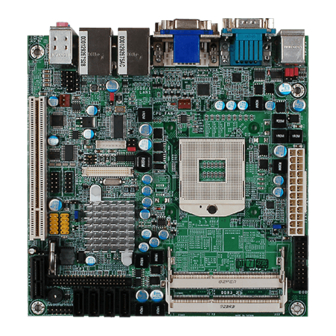
Hardware Installation Chapter 2 - Hardware Installation System Board Layout PS/2 power select (JP1) PS/2 Mouse PS/2 KB Standby Power LED ATX power COM2 RS232/Power Power-on select (JP4) select ( COM 2 COM 1 Chrontel CH7318C DVI-I CPU fan Panel power LAN 1 (Intel) select ( USB 1... -
Page 17: System Memory
Hardware Installation Important: Electrostatic discharge (ESD) can damage your system board, processor, disk drives, add-in boards, and other components. Perform the upgrade instruction procedures described at an ESD workstation only. If such a station is not available, you can provide some ESD protection by wearing an antistatic wrist strap and attaching it to a metal part of the system chassis. -
Page 18: Installing The Dim Module
Hardware Installation Installing the DIM Module Note: The system board used in the following illustrations may not resemble the actual one. These illustrations are for reference only. 1. Make sure the PC and all other peripheral devices connected to it has been powered down. - Page 19 Hardware Installation 5. Grasping the module by its edges, align the module into the socket at an ap- proximately 30 degrees angle. Apply firm even pressure to each end of the module until it slips down into the socket. The contact fingers on the edge of the module will almost completely disappear inside the socket.
-
Page 20: Cpu
Hardware Installation Overview The system board is equipped with a surface mount rPGA 988A CPU socket. Note: The system board used in the following illustrations may not resemble the actual one. These illustrations are for reference only. Installing the CPU 1. - Page 21 Hardware Installation 5. Position the CPU above the socket. The gold triangular mark on the CPU must align with pin 1 of the CPU socket. Important: Handle the CPU by its edg- es and avoid touching the Gold triangular mark pins.
-
Page 22: Installing The Fan And Heat Sink
Hardware Installation Installing the Fan and Heat Sink The CPU must be kept cool by using a CPU fan with heat sink. Without sufficient air circulation across the CPU and heat sink, the CPU will overheat damaging both the CPU and system board. Note: •... -
Page 23: Hardware Installation
Hardware Installation 4. Place the fan / heat sink assembly on top of the CPU. The 4 screws around the heat sink must match the screw holes of the retention module base. We strongly recommend using this type of fan / heat sink assembly because it provides adequate cooling to the components of the system board. -
Page 24: Jumper Settings
Hardware Installation Jumper Settings Clear CMOS Data 1-2 On: Normal (default) 2-3 On: Clear CMOS Data If you encounter the following, a) CMOS data becomes corrupted. b) You forgot the supervisor or user password. you can reconfigure the system with the default values stored in the ROM BIOS. To load the default values stored in the ROM BIOS, please follow the steps below. -
Page 25: Ps/2 Power Select
Hardware Installation PS/2 Power Select 1-2 On: 5V (default) 2-3 On: 5V_standby JP1 is used to select the power of the PS/2 keyboard/mouse port. Selecting 5V_standby will allow you to use the PS/2 keyboard or PS/2 mouse to wake up the system. -
Page 26: Usb Power Select
Hardware Installation USB Power Select 1-2 On: 5V (default) USB 0-1, 8-9 power select (JP2) 2-3 On: 5V_standby JP2 (for USB 0-1 and USB 8-9) is used to select the power of the USB ports. Se- lecting 5V_standby will allow you to use a USB device to wake up the system. Important: If you are using the Wake-On-USB Keyboard/Mouse function for 2 USB ports, the 5V_standby power source of your power supply must support... -
Page 27: Panel Power Select
Hardware Installation Panel Power Select 1-2 On: 12V 3-4 On: 5V 5-6 On: 3.3V (default) JP8 is used to select the power supplied to the LCD panel. Important: Before powering-on the system, make sure JP8’s setting matches the LCD panel’s specification. Selecting the incorrect voltage will seriously damage the LCD panel. -
Page 28: Com 3 Rs232/Rs485 Select
Hardware Installation COM 3 RS232/RS485 Select JP11 JP11 is used to confi gure COM 3 to RS232 or RS485. The pin function of COM 3 will vary according to the jumper’s setting. JP11 1-2 On: RS232 5-6 On: RS485 (default) COM 3... -
Page 29: Com 2 Rs232/Power Select
Hardware Installation COM 2 RS232/Power Select 1-3, 2-4 On: 3-5 (12V), 4-6 (5V) On: RS232 standard RS232 with power (default) COM 2 1 2 3 4 5 1 2 3 4 5 6 7 8 9 6 7 8 9... -
Page 30: Power-On Select
Hardware Installation Power-on Select 1-2 On: Power-on via power button (default) 2-3 On: Power-on via AC power; Power-on via WOL after G3 To power-on via WOL after G3: 1. Set JP6 pins 2 and 3 to On. 2. Set the “After G3” field to Power Off/WOL. 3. Set the “Wake On LAN From S5” to Enabled. The BIOS fields are in the “South Bridge” submenu (Chipset menu) of the AMI BIOS utility. -
Page 31: Rear Panel I/O Ports
Hardware Installation Rear Panel I/O Ports LAN 1 LAN 2 PS/2 (Intel) (Realtek) COM 2 Mouse Mic-in Line-in Line-out PS/2 COM 1 DVI-I USB 0-1 USB 8-9 (DVI-D signal only) The rear panel I/O ports consist of the following: • PS/2 mouse port • PS/2 keyboard port • 2 COM ports • VGA port • DVI-I port (DVI-D signal only) •... -
Page 32: Ps/2 Mouse And Ps/2 Keyboard Ports
Hardware Installation PS/2 Mouse and PS/2 Keyboard Ports PS/2 Mouse PS/2 KB These ports are used to connect a PS/2 mouse and a PS/2 keyboard. The PS/2 mouse port uses IRQ12. If a mouse is not connected to this port, the system will reserve IRQ12 for other expansion cards. Important: Make sure to turn off your computer prior to connecting or disconnecting a mouse or keyboard. Failure to do so may damage the system board. Wake-On-PS/2 Keyboard/Mouse The Wake-On-PS/2 Keyboard/Mouse function allows you to use the PS/2 keyboard or PS/2 mouse to power-on the system. To use this function: • Jumper Setting JP1 must be set to “2-3 On: 5V_standby”. Refer to “PS/2 Power Select” in this chapter for more information. -
Page 33: Com (Serial) Ports
Hardware Installation COM (Serial) Ports COM 2 COM 1 COM 3 COM 4 1 2 3 4 5 6 7 8 9 COM 4 COM 1 and COM 2 COM 1, COM 2 and COM 4 are fi xed at RS232. COM 3’s pin defi... - Page 34 Hardware Installation Connecting External Serial Ports Your COM port may come mounted on a card-edge bracket. Install the card-edge bracket to an available slot at the rear of the system chassis then insert the se- rial port cable to the COM connector. Make sure the colored stripe on the ribbon cable is aligned with pin 1 of the COM connector. BIOS Setting Configure the serial ports in the Advanced menu (“UART Configuration” submenu) of the BIOS. Refer to chapter 3 for more information.
-
Page 35: Vga Port
Hardware Installation VGA Port The VGA port is used for connecting a VGA monitor. Connect the monitor’s 15-pin D-shell cable connector to the VGA port. After you plug the monitor’s cable con- nector into the VGA port, gently tighten the cable screws to hold the connector in place. BIOS Setting Configure the onboard VGA in the Advanced menu of the BIOS. Refer to chapter 3 for more information. -
Page 36: Dvi-I Port
Hardware Installation DVI-I Port DVI-I The DVI-I port is used to connect an LCD monitor. This port supports DVI-D sig- nal only. Connect the display device’s cable connector to the DVI-I port. After you plug the cable connector into the port, gently tighten the cable screws to hold the connec- tor in place. BIOS Setting Configure the display device in the Advanced menu of the BIOS. Refer to chapter 3 for more information. -
Page 37: Rj45 Lan Port
Hardware Installation RJ45 LAN Ports LAN 1 (Intel) LAN 2 (Realtek) The LAN ports allow the system board to connect to a local area network by means of a network hub. BIOS Setting Configure the onboard LAN ports in the Chipset menu (“South Bridge submenu) of the BIOS. Refer to chapter 3 for more information. Driver Installation Install the LAN drivers. Refer to chapter 4 for more information. -
Page 38: Usb Ports
Hardware Installation USB Ports USB 1 USB 0 USB 2-3 USB 9 USB 4-5 USB 8 USB allows data exchange between your computer and a wide range of simulta- neously accessible external Plug and Play peripherals. The system board is equipped with four onboard USB 2.0/1.1 ports. The two 10-pin connectors allow you to connect 4 additional USB 2.0/1.1 ports. The USB ports may be mounted on a card-edge bracket. Install the card-edge bracket to an available slot at the rear of the system chassis then insert the USB port cables to a connector. - Page 39 Hardware Installation Wake-On-USB Keyboard/Mouse The Wake-On-USB Keyboard/Mouse function allows you to use a USB keyboard or USB mouse to wake up a system from the S3 (STR - Suspend To RAM) state. To use this function: • Jumper Setting JP2 must be set to “2-3 On: 5V_standby”. Refer to “USB Power Select” in this chapter for more information. Important: If you are using the Wake-On-USB Keyboard/Mouse function for 2 USB ports, the 5V_standby power source of your power supply must support ≥1.5A. For 3 or more USB ports, the 5V_standby power source of your power supply must support ≥2A.
-
Page 40: Audio
Hardware Installation Audio Rear audio Mic-in Line-in Line-out Front audio Rear Audio The system board is equipped with 3 audio jacks. A jack is a one-hole connecting interface for inserting a plug. • Mic-in Jack (Pink) This jack is used to connect an external microphone. • Line-in Jack (Light Blue) This jack is used to connect any audio devices such as Hi-fi set, CD player, tape player, AM/FM radio tuner, synthesizer, etc. • Line-out Jack (Lime) This jack is used to connect a headphone or external speakers. Front Audio The front audio connector allows you to connect to the second line-out and mic- in jacks that are at the front panel of your system. - Page 41 Hardware Installation BIOS Setting Configure the onboard audio in the Chipset menu (“South Bridge” submenu) of the BIOS. Refer to chapter 3 for more information. Driver Installation Install the audio driver. Refer to chapter 4 for more information.
-
Page 42: I/O Connectors
Hardware Installation I/O Connectors CD-in Internal Audio Connector Ground Ground Right audio Left audio channel channel The CD-in connector is used to receive audio from a CD-ROM drive, TV tuner or MPEG card. -
Page 43: S/Pdif-Out Connector
Hardware Installation S/PDIF Connector SPDIF out Ground SPDIF in The S/PDIF connector is used to connect an external S/PDIF port. Your S/PDIF port may be mounted on a card-edge bracket. Install the card-edge bracket to an available slot at the rear of the system chassis then connect the audio cable to the S/PDIF connector. Make sure pin 1 of the audio cable is aligned with pin 1 of the S/PDIF connector. -
Page 44: Lvds Lcd Panel And Lcd/Inverter Power Connector
Hardware Installation LVDS LCD Panel Connector LCD/Inverter Power Connector LCD/Inverter LVDS LCD power panel The system board allows you to connect a LCD Display Panel by means of the LVDS LCD panel connector and the LCD/Inverter power connector. These connec- tors transmit video signals and power from the system board to the LCD Display Panel. - Page 45 Hardware Installation LVDS LCD Panel Connector Pins Pins Function Function LVDS_Out3+ LVDS_Out7+ LVDS_Out3- LVDS_Out7- LVDS_Out2+ LVDS_Out6+ LVDS_Out2- LVDS_Out6- LVDS_Out1+ LVDS_Out5+ LVDS_Out1- LVDS_Out5- LVDS_Out0+ LVDS_Out4+ LVDS_Out0- LVDS_Out4- LVDS_CLK1+ LVDS_CLK2+ LVDS_CLK1- LVDS_CLK2- LVDS_DDCCLK N. C. LVDS_DDCDAA N. C. Panel Power Panel Power Panel Power Panel Power LCD/Inverter Power Connector...
-
Page 46: Digital I/O Connector
Hardware Installation Digital I/O Connector The Digital I/O connector provides powering-on function to an external device that is connected to this connector. Function Pins Pins Function +12V DIO7 +12V DIO6 DIO5 DIO4 DIO3 DIO2 V_5P0_STBY DIO1 V_5P0_STBY DIO0... -
Page 47: Sata (Serial Ata) Connectors
Hardware Installation SATA (Serial ATA) Connectors SATA 0 SATA 1 SATA 4 SATA 5 The Serial ATA connectors are used to connect Serial ATA devices. Connect one end of the Serial ATA cable to a SATA connector and the other end to your Serial ATA device. -
Page 48: Ide Connector
Hardware Installation IDE Connector The IDE connector is used to connect hard drives. The connector on the IDE cable can be inserted into this connector only if pin 1 of the cable is aligned with pin 1 of this connector. The IDE connector supports 2 devices, a Master and a Slave. Use an IDE ribbon cable to connect the drives to the system board. An IDE ribbon cable have 3 connectors on them, one that plugs into the IDE connector on the system board and the other 2 connects to IDE devices. The connector at the end of the cable is for the Master drive and the connector in the middle of the cable is for the Slave... - Page 49 Hardware Installation Important: If you encountered problems while using an ATAPI CD-ROM drive that is set in Master mode, please set the CD-ROM drive to Slave mode. Some ATAPI CD-ROMs may not be recognized and cannot be used if incorrectly set in Master mode. BIOS Setting Configure the onboard IDE in the Advanced menu of the BIOS. Refer to chapter 3 for more information.
-
Page 50: Cooling Fan Connectors
Hardware Installation Cooling Fan Connectors Ground Power Sense CPU fan Ground Sense Power System fan The fan connectors are used to connect cooling fans. The cooling fans will provide adequate airflow throughout the chassis to prevent overheating the CPU and sys- tem board components. BIOS Setting The Advanced menu (“PC Health Status” submenu) of the BIOS will display the current speed of the cooling fan. Refer to chapter 3 for more information. -
Page 51: Chassis Instrusion Connector
Hardware Installation Chassis Instrusion Connector Chassis signal Ground The board supports the chassis intrusion detection function. Connect the chas- sis intrusion sensor cable from the chassis to this connector. When the system’s power is on and a chassis intrusion occurred, an alarm will sound. When the system’s power is off and a chassis intrusion occurred, the alarm will sound only when the system restarts. -
Page 52: Power Connectors
Hardware Installation Power Connector Connect a 24-pin ATX main power connector from the power supply unit to the 24-pin power connector. The connector from the power supply unit is designed to fit the 24-pin connector in only one orientation. Make sure to find the proper ori- entation before plugging the connector. -
Page 53: Standby Power Led
Hardware Installation Standby Power LED Standby Power LED This LED will lit red when the system is in the standby mode. It indicates that there is power on the system board. Power-off the PC then unplug the power cord prior to installing any devices. Failure to do so will cause severe damage to the motherboard and components. -
Page 54: Front Panel Connectors
Hardware Installation Front Panel Connectors PWR-LED HDD-LED PWR-BTN RESET-SW HDD-LED - HDD LED This LED will light when the hard drive is being accessed. RESET SW - Reset Switch This switch allows you to reboot without having to power off the system. PWR-BTN - Power Switch This switch is used to power on or off the system. PWR-LED - Power/Standby LED When the system’s power is on, this LED will light. When the system is in the S1 (POS - Power On Suspend) state, it will blink every second. When the system is in the S3 (STR - Suspend To RAM) state, it will blink every 4 seconds. -
Page 55: Expansion Slots
Hardware Installation Expansion Slots PCI Express x1 PCI Express x1 Install PCI Express cards such as network cards or other cards that comply to the PCI Express specifications into the PCI Express x1 slot. PCI Slot The PCI slot supports expansion cards that comply with PCI specifications. You can install a PCI expansion card or a customized riser card designed for 1, 2 or 3 PCI slots expansion (for low profile PCI card only) into the PCI slot. -
Page 56: Battery
Hardware Installation Battery Battery The lithium ion battery powers the real-time clock and CMOS memory. It is an auxiliary source of power when the main power is shut off. Safety Measures • Danger of explosion if battery incorrectly replaced. • Replace only with the same or equivalent type recommend by the manufac- turer. • Dispose of used batteries according to local ordinance. -
Page 57: Chapter 3 - Bios Setup
BIOS Setup Chapter 3 - BIOS Setup Overview The BIOS is a program that takes care of the basic level of communication be- tween the CPU and peripherals. It contains codes for various advanced features found in this system board. The BIOS allows you to configure the system and save the configuration in a battery-backed CMOS so that the data retains even when the power is off. -
Page 58: Legends
BIOS Setup Legends Keys Function Right and Left arrows Moves the highlight left or right to select a menu. Up and Down arrows Moves the highlight up or down between submenus or fields. <Esc> Exits to the BIOS Setup Utility. + (plus key) Scrolls forward through the values or options of the highlighted field. -
Page 59: Main
BIOS Setup Main The Main menu is the first screen that you will see when you enter the BIOS Setup Utility. BIOS SETUP UTILITY Main Advanced Chipset Boot Security Save & Exit Set the Date. Use Tab to BIOS Information switch between Data BIOS Vendor American Megatrends... -
Page 60: Advanced
BIOS Setup Advanced The Advanced menu allows you to configure your system for basic operation. Some entries are defaults required by the system board, while others, if enabled, will improve the performance of your system or let you set some features ac- cording to your preference. -
Page 61: Pci Subsystem Settings
BIOS Setup PCI Subsystem Settings This section is used to configure the PCI, PCI-X and PCI Express settings. BIOS SETUP UTILITY Advanced In case of multiple Option V 2.02.01 PCI Bus Driver Version ROMs (Legacy and EFI PCI ROM Priority [EFI Compatible ROM] Compatible), specifies what PCI Option ROM... -
Page 62: Tpm Support
BIOS Setup Trusted Computing (Optional) This section configures settings relevant to Trusted Computing innovations. BIOS SETUP UTILITY Advanced Enables or Disables TPM Configuration TPM support. O.S. will TPM Support [Disabled] not show TPM. Reset of platform is required. Current TPM Status Information TPM Support Off Select Screen →... -
Page 63: Pc Health Status
BIOS Setup PC Health Status This section displays the SIO hardware health monitor. BIOS SETUP UTILITY Advanced Smart Fan Function Smart Fan Function Case Open Beep [Disabled] System Hardware Monitor CPU Temperature : +35 C System Temperature : +26 C CPU FAN Speed : 7042 RPM System FAN Speed (1) - Page 64 BIOS Setup Case Open Beep Set this field to Enabled to allow the system to alert you of a chassis intru- sion event. System Hardware Monitor to VBAT These fields will show the temperature, fan speed and output voltage of the monitored devices or components.
-
Page 65: Bios Setup
BIOS Setup ACPI Power Management Configuration This section is used to configure the ACPI power management. BIOS SETUP UTILITY Advanced ACPI Power Management Configuration Enables or Disables BIOS ACPI Auto Configuration. Enable ACPI Auto Configuration [Disabled] ACPI Sleep State [S3 (Suspend to R...)] Resume by PME [Disabled] Resume by Ring... - Page 66 BIOS Setup Resume by RTC Alarm Enabled When Enabled, you can set the date and time you would like the Soft Power Down (Soft-Off) PC to power-on. However, if the system is being accessed by incoming calls or the network (Resume On Ring/LAN) prior to the alarm date and time, the system will give priority to the incoming calls or network.
-
Page 67: Cpu Configuration
BIOS Setup CPU Configuration This section is used to configure the CPU. It will also display the detected CPU information. BIOS SETUP UTILITY Advanced CPU Configuration Enabled for Windows XP and Linux (OS optimized Processor Type Intel (R) Core (TM) i5 CPU for Hyper-Threading EMT64 Supported... -
Page 68: Sata Configuration
BIOS Setup SATA Configuration This section is used to configure SATA functions. BIOS SETUP UTILITY Advanced SATA Configuration (1) IDE Mode. (2) AHCI Mode. SATA Port 0 Not Present (3) RAID Mode. SATA Port 1 Not Present SATA Port 4 Not Present SATA Port 5 Not Present... -
Page 69: Video Function Configuration
BIOS Setup Video Function Configuration BIOS SETUP UTILITY Advanced Video Function Configuration Select DVMT/FIXED Mode Memory size used DVMT/FIXED Memory [256MB] by Internal Graphics IGD - Boot Type [VBIOS Default ] Device LCD Panel Type [VBIOS Default] Panel Scaling [Auto] Active LFP [Int-LVDS] Select Screen... - Page 70 BIOS Setup Intel TXT (LT) Configuration This section is used to configure the Intel Trusted Execution technology. BIOS SETUP UTILITY Advanced Intel Trusted Execution Technology Configuration Intel TXT(LT) Support [Disabled] Select Screen → ←: Select Item ↑↓: Enter: Select +/ -: Change Opt.
-
Page 71: Usb Configuration
BIOS Setup USB Configuration This section is used to configure USB. BIOS SETUP UTILITY Advanced Enables Legacy USB USB Configuration support. AUTO option disables legacy support if USB Devices: no USB devices are 2 Hubs connected. DISABLE option will keep USB Legacy USB Support [Enabled] devices available only for... - Page 72 BIOS Setup Super IO Configuration This section is used to configure the I/O functions supported by the onboard Super I/O chip. BIOS SETUP UTILITY Advanced Super IO Configuration Restore AC Power Loss Help. Super IO Chip Fintek F71879 [Off] Restore AC Power Loss Select Screen →...
-
Page 73: Serial Port
BIOS Setup UART Configuration This section is used to configure the serial port functions. BIOS SETUP UTILITY Advanced UART Configuration Set Parameters of Serial Port 0 (COMA) Super IO Chip Fintek F81216 Serial Port 1 Configure Serial Port 2 Configure ... -
Page 74: Amt Configuration
BIOS Setup AMT Configuration BIOS SETUP UTILITY Advanced [Enabled] AMT Help Unconfigure AMT/ME [Disabled] Select Screen → ←: Select Item ↑↓: Enter: Select +/ -: Change Opt. General Help Previous Values Optimized Defaults Save ESC: Exit Version 2.00.1201. Copyright (C) 2009 American Megatrends, Inc. Enables or disables the AMT function. -
Page 75: Ata Controller
BIOS Setup Onboard ATA Controller Configuration BIOS SETUP UTILITY Advanced PATA Primary Master Not Present Select an operative mode for ATA PATA Primary Slave Not Present controller. ATA Controller [IDE Mode] Select Screen → ←: Select Item ↑↓: Enter: Select +/ -: Change Opt. -
Page 76: Chipset
BIOS Setup Chipset Configures relevant chipset functions. BIOS SETUP UTILITY Main Advanced Chipset Boot Security Save & Exit North Bridge Parameters North Bridge South Bridge ME Subsystem Select Screen ← →: Select Item ↑↓: Enter: Select +/ -: Change Opt. -
Page 77: North Bridge
BIOS Setup North Bridge BIOS SETUP UTILITY Chipset Memory Information Low MMIO resources align at 64MB/1024MB CPU Type Arrandale Total Memory 2048 MB (DDR3 1066) Memory Slot 0 0 MB (DDR3 1066) Memory Slot 1 2048 MB (DDR3 1066) CAS# Latency (tCL) RAS# Active Time (tRAS) Row Precharge Time (tRP) RAS# to CAS# Delay (tRCD) -
Page 78: South Bridge
BIOS Setup South Bridge BIOS SETUP UTILITY Chipset SB Chipset Configuration GbE Controller help. GbE Controller [Enable] Wake On Lan From S5 [Disable] After G3 [Power On] Audio Configuration Azalia HD Audio [Enabled] High Precision Event Timer Configuration High Precision Timer [Enabled] USB Configuration Select Screen → ←: Select Item ↑↓: Enter: Select +/ -:... -
Page 79: All Usb Devices
BIOS Setup USB Configuration BIOS SETUP UTILITY Chipset USB Configuration Enable/Disable All USB Devices All USB Devices [Enabled] [Enabled] EHCI Controller 1 EHCI Controller 2 [Enabled] Select Screen → ←: Select Item ↑↓: Enter: Select +/ -: Change Opt. General Help Previous Values Optimized Defaults Save ESC: Exit... - Page 80 BIOS Setup ME Subsystem BIOS SETUP UTILITY Chipset Intel ME Subsystem Configuration ME Subsystem Help ME Version [Enabled] ME Subsystem [Enabled] End of Post Message [Enabled] Execute MEBx Select Screen → ←: Select Item ↑↓: Enter: Select +/ -: Change Opt. General Help Previous Values Optimized Defaults...
-
Page 81: Boot
BIOS Setup Boot BIOS SETUP UTILITY Main Advanced Chipset Boot Security Save & Exit Enables/Disables Quiet Boot Configuration Quiet Boot [Disabled] Boot option Fast Boot [Disabled] Setup Prompt Timeout Bootup NumLock State [On] CSM16 Module Version 07.58 Boot Option Priorities Boot Option #1 [Built-in EFI Shell] Select Screen... -
Page 82: Security
BIOS Setup Security BIOS SETUP UTILITY Main Advanced Chipset Boot Security Save & Exit Password Description Set Setup Administrator Password. If only the Administrator’s password is set, then this only limits access to Setup and is only asked for when entering Setup. If only the User’s password is set, then this is a power on password and must be entered to boot or enter setup. -
Page 83: Save & Exit
BIOS Setup Save & Exit BIOS SETUP UTILITY Main Advanced Chipset Boot Security Save & Exit Exit system setup after Save Changes and Reset saving the changes. Discard Changes and Reset Save Options Save Changes Discard Changes Restore Defaults Save as User Defaults Restore User Defaults Boot Override Built-in EFI Shell... -
Page 84: Updating The Bios
BIOS Setup Updating the BIOS To update the BIOS, you will need the new BIOS file and a flash utility, AFUDOS. EXE. Please contact technical support or your sales representative for the files. To execute the utility, type: A:> AFUDOS BIOS_File_Name /b /p /n then press <Enter>. -
Page 85: Chapter 4 - Supported Software
Supported Software Chapter 4 - Supported Software Drivers, Utilities and Software Applications The CD that came with the system board contains drivers, utilities and software applications required to enhance the performance of the system board. Insert the CD into a CD-ROM drive. The autorun screen (Mainboard Utility CD) will appear. -
Page 86: Microsoft .Net Framework 3.5
Supported Software Microsoft .NET Framework 3.5 To install the driver, click “Microsoft .NET Framework 3.5” on the main menu. 1. Setup is ready to install the driver. Click Next. 2. Read the license agreement then click “I accept the terms of the License Agree- ment.”. - Page 87 Supported Software 3. Setup is now installing the driver. 4. Click Finish. Reboot the system for the new soft- ware installation to take effect.
-
Page 88: Microsoft Directx 9.0C Driver
Supported Software Microsoft DirectX 9.0C Driver To install the utility, click “Microsoft DirectX 9.0C Driver” on the main menu. 1. C l i c k “ I a c c e p t t h e agreement” then click Next. 2. - Page 89 Supported Software 3. Click Finish. Reboot the system for DirectX to take effect.
-
Page 90: Intel Chipset Software Installation Utility
Supported Software Intel Chipset Software Installation Utility The Intel Chipset Software Installation Utility is used for updating Windows files so that the Intel chipset can be recognized and configured properly in the system. To install the utility, click “Intel Chipset Software Installation Utility” on the main menu. - Page 91 Supported Software 3. Go through the readme document for more installa- tion tips then click Next. 4. After all setup operations are done, click Next. 5. Click Finish to exit setup.
-
Page 92: Intel Graphics Drivers
Supported Software Intel Graphics Drivers To install the driver, click “Intel Graphics Drivers” on the main menu. 1. Setup is ready to install the graphics driver. Click Next. 2. Read the license agreement then click Yes. 3. Go through the readme document for more installa- tion tips then click Next. - Page 93 Supported Software 4. Setup is currently installing the driver. After installation has completed, click Next. 5. Click “Yes, I want to restart this computer now.” then click Finish. Restarting the system will allow the new software in- stalllation to take effect.
-
Page 94: Intel Management Engine Drivers
Supported Software Intel Management Engine Drivers To install the driver, click “Management Engine Interface Drivers” on the main menu. 1. Setup is ready to install the driver. Click Next. 2. Read the license agreement then click Yes. 3. Go through the readme document for more installa- tion tips then click Next. - Page 95 Supported Software 4. Setup is currently installing the driver. After installation has completed, click Next. 5. After completing installa- tion, click Finish.
-
Page 96: Audio Drivers
Supported Software Audio Drivers To install the driver, click “Audio Drivers” on the main menu. 1. Setup is ready to install the driver. Click Next. 2. Click “Yes, I want to restart my computer now” then click Finish. Restarting the system will allow the new software in- stallation to take effect. -
Page 97: Intel Lan Drivers
Supported Software Intel LAN Drivers To install the driver, click “Intel LAN Drivers” on the main menu. 1. Setup is ready to install the driver. Click Next. 2. Click “I accept the terms in the license agreement” then click “Next”. 3. - Page 98 Supported Software 4. Click Install to begin the installation. 5. After completing installa- tion, click Finish.
-
Page 99: Realtek Lan Drivers
Supported Software Realtek LAN Drivers To install the driver, click “Realtek LAN Drivers” on the main menu. 1. Setup is ready to install the driver. Click Next. 2. Click Install to begin the installation. 3. After completing installa- tion, click Finish. -
Page 100: Myguard Hardware Monitor
Supported Software MyGuard Hardware Monitor To install the driver, click “MyGuard Hardware Monitor” on the main menu. 1. Setup is ready to install the utility. Click Next. 2. Click Install to begin instal- lation. 3. Setup is currently installing the utility. - Page 101 Supported Software 4. After completing instal- lation, click Finish to exit setup.
-
Page 102: Adobe Acrobat Reader 7.0
Supported Software Adobe Acrobat Reader 9.3 To install the reader, click “Adobe Acrobat Reader 9.3” on the main menu. 1. Click Next to install or click Change Destination Folder to select another folder. 2. Click Install to begin instal- lation. - Page 103 Supported Software 3. Click Finish to exit installa- tion.
-
Page 104: Chapter 5 - Raid
RAID Chapter 5 - RAID The system board allows configuring RAID on Serial ATA drives. It supports RAID 0, RAID 1, RAID 5 and RAID 10. RAID Levels RAID 0 (Striped Disk Array without Fault Tolerance) RAID 0 uses two new identical hard disk drives to read and write data in parallel, interleaved stacks. -
Page 105: Settings
RAID Settings To enable the RAID function, the following settings are required. 1. Connect the Serial ATA drives. 2. Configure Serial ATA in the AMI BIOS. 3. Configure RAID in the RAID BIOS. 4. Install the RAID driver during OS installation. 5. - Page 106 RAID Step 4: Install the RAID Driver During OS Installation The RAID driver must be installed during the Windows XP or Windows 2000 in- ® ® stallation using the F6 installation method. This is required in order to install the operating system onto a hard drive or RAID volume when in RAID mode or onto a hard drive when in AHCI mode.
- Page 107 RAID Step 5: Install the Intel Rapid Storage Drivers The Intel Rapid Storage Drivers can be installed from within Windows. It allows RAID volume management (create, delete, migrate) from within the operating system. It will also display useful SATA device and RAID volume information. The user interface, tray icon service and monitor service allow you to monitor the current status of the RAID volume and/or SATA drives.
- Page 108 RAID 5. Read the license agree- ment then click Yes. 6. Go through the readme document to view system requirements and installa- tion information then click Next. 7. Click “Yes, I want to restart my computer now” then click Finish.
-
Page 109: Chapter 6 - Intel Amt Settings
Intel AMT Settings Chapter 6 - Intel AMT Settings Overview Intel Active Management Technology (Intel ® AMT) combines hardware and soft- ware solution to provide maximum system defense and protection to networked systems. The hardware and software information are stored in non-volatile memory. With its built-in manageability and latest security applications, Intel AMT provides the ®... -
Page 110: Enable Intel® Amt In The Ami Bios
Intel AMT Settings Enable Intel AMT in the AMI BIOS ® 1. Power-on the system then press <Del> to enter the main menu of the AMI BIOS. 2. In the Advanced menu, select AMT Configuration. BIOS SETUP UTILITY Main Chipset Boot Security Save &... - Page 111 Intel AMT Settings 4. In the Chipset menu, select ME Subsystem. BIOS SETUP UTILITY Main Advanced Chipset Boot Security Save & Exit North Bridge Parameters North Bridge South Bridge ME Subsystem Select Screen ← →: Select Item ↑↓: Enter: Select +/ -:...
- Page 112 Intel AMT Settings 6. In the Save & Exit menu, select Save Changes and Exit then select OK. BIOS SETUP UTILITY Main Advanced Chipset Boot Security Save & Exit Save Changes and Reset Exit system setup after Discard Changes and Reset saving the changes.
-
Page 113: Enable Intel® Amt In The Intel® Management Engine Bios Extension (Mebx) Screen
Intel AMT Settings Enable Intel AMT in the Intel Management ® ® Engine BIOS Extension (MEBX) Screen 1. When the system reboots, the following message will be displayed. Press <Ctrl-P> as soon as the message is displayed; as this message will be dis- played for only a few seconds. - Page 114 Intel AMT Settings 3. Enter a new password in the space provided under Intel(R) ME New Password then press Enter. The password must include: • 8-32 characters • Strong 7-bit ASCII characters excluding : , and ” characters • At least one digit character (0, 1, ...9) • At least one 7-bit ASCII non alpha-numeric character, above 0x20, (e.g. !, $, ;) • Both lower case and upper case characters Intel(R) Management Engine BIOS Extension v6.0.3.0014/Intel(R) ME v6.0.0.1184 Copyright(C) 2003-09 Intel Corporation.
- Page 115 Intel AMT Settings 4. You will be asked to verify the password. Enter the same new password in the space provided under Verify Password then press Enter. Intel(R) Management Engine BIOS Extension v6.0.3.0014/Intel(R) ME v6.0.0.1184 Copyright(C) 2003-09 Intel Corporation. All Rights Reserved. MAIN MENU Intel(R) ME General Settings ...
- Page 116 Intel AMT Settings 6. Select Intel(R) ME State Control then press Enter. Intel(R) Management Engine BIOS Extension v6.0.3.0014/Intel(R) ME v6.0.0.1184 Copyright(C) 2003-09 Intel Corporation. All Rights Reserved. INTEL(R) ME PLATFORM CONFIGURATION Intel(R) ME State Control Change ME Password Password Policy Network Setup ...
- Page 117 Intel AMT Settings 8. Select Change ME Password then press Enter. You will be prompted for a password. The default password is “admin”. Enter the default password in the space provided under Intel(R) ME Password then press Enter. • 8-32 characters •...
- Page 118 Intel AMT Settings 9. Select Password Policy then press Enter. You may choose to use a password only during setup and configuration or to use a password anytime the system is being accessed. Intel(R) Management Engine BIOS Extension v6.0.3.0014/Intel(R) ME v6.0.0.1184 Copyright(C) 2003-09 Intel Corporation.
- Page 119 Intel AMT Settings Select Network Setup then press Enter. Intel(R) Management Engine BIOS Extension v6.0.3.0014/Intel(R) ME v6.0.0.1184 Copyright(C) 2003-09 Intel Corporation. All Rights Reserved. INTEL(R) ME PLATFORM CONFIGURATION Intel(R) ME State Control Change ME Password Password Policy Network Setup Activate Network Access Unconfigure Network Access Remote Setup and Configuration ...
- Page 120 Intel AMT Settings In the Intel(R) ME Network Name Settings menu, select Host Name then press Enter. Intel(R) Management Engine BIOS Extension v6.0.3.0014/Intel(R) ME v6.0.0.1184 Copyright(C) 2003-09 Intel Corporation. All Rights Reserved. INTEL(R) ME NETWORK NAME SETTINGS Host Name Domain Name Shared/Dedicated FQDN Dynamic DNS Update Previous Menu...
- Page 121 Intel AMT Settings Select Domain Name then press Enter. Enter the domain name then press Enter. Intel(R) Management Engine BIOS Extension v6.0.3.0014/Intel(R) ME v6.0.0.1184 Copyright(C) 2003-09 Intel Corporation. All Rights Reserved. INTEL(R) ME NETWORK NAME SETTINGS Host Name Domain Name Shared/Dedicated FQDN Dynamic DNS Update Previous Menu...
- Page 122 Intel AMT Settings Select Dynamic DNS Update then press Enter. Select Enabled or Disabled then press Enter. Intel(R) Management Engine BIOS Extension v6.0.3.0014/Intel(R) ME v6.0.0.1184 Copyright(C) 2003-09 Intel Corporation. All Rights Reserved. INTEL(R) ME NETWORK NAME SETTINGS Host Name Domain Name Shared/Dedicated FQDN Dynamic DNS Update Previous Menu...
- Page 123 Intel AMT Settings In the TCP/IP Settings menu, select Wired LAN IPV4 Configuration then press Enter. Intel(R) Management Engine BIOS Extension v6.0.3.0014/Intel(R) ME v6.0.0.1184 Copyright(C) 2003-09 Intel Corporation. All Rights Reserved. TCP/IP SETTINGS Wired LAN IPV4 Configuration Wired LAN IPV6 Configuration ...
- Page 124 Intel AMT Settings A list of options in the Wired LAN IPV4 Configuration menu will appear. Intel(R) Management Engine BIOS Extension v6.0.3.0014/Intel(R) ME v6.0.0.1184 Copyright(C) 2003-09 Intel Corporation. All Rights Reserved. WIRED LAN IPV4 CONFIGURATION DHCP Mode IPV4 Address Subnet Mask Address Default Gateway Address Preferred DNS Address Alternate DNS Address...
- Page 125 Intel AMT Settings Select Subnet Mask Address then press Enter. Enter the subnet mask ad- dress then press Enter. Intel(R) Management Engine BIOS Extension v6.0.3.0014/Intel(R) ME v6.0.0.1184 Copyright(C) 2003-09 Intel Corporation. All Rights Reserved. WIRED LAN IPV4 CONFIGURATION DHCP Mode IPV4 Address Subnet Mask Address Default Gateway Address...
- Page 126 Intel AMT Settings Select Preferred DNS Address then press Enter. Enter the preferred DNS address then press Enter. Intel(R) Management Engine BIOS Extension v6.0.3.0014/Intel(R) ME v6.0.0.1184 Copyright(C) 2003-09 Intel Corporation. All Rights Reserved. WIRED LAN IPV4 CONFIGURATION DHCP Mode IPV4 Address Subnet Mask Address Default Gateway Address Preferred DNS Address...
- Page 127 Intel AMT Settings 26. Select Previous Menu until you return to the TCP/IP Settings menu. Se- lect Wired LAN IPV6 Configuration then press Enter. Intel(R) Management Engine BIOS Extension v6.0.3.0014/Intel(R) ME v6.0.0.1184 Copyright(C) 2003-09 Intel Corporation. All Rights Reserved. TCP/IP SETTINGS Wired LAN IPV4 Configuration ...
- Page 128 Intel AMT Settings A list of options in the Wired LAN IPV6 Configuration menu will appear. Intel(R) Management Engine BIOS Extension v6.0.3.0014/Intel(R) ME v6.0.0.1184 Copyright(C) 2003-09 Intel Corporation. All Rights Reserved. WIRED LAN IPV6 CONFIGURATION IPV6 Feature Selection IPV6 Interface ID Type IPV6 Address IPV6 Default Router Preferred DNS IPV6 Address...
- Page 129 Intel AMT Settings Select IPV6 Address then press Enter. Enter the IPV6 address then press Enter. Intel(R) Management Engine BIOS Extension v6.0.3.0014/Intel(R) ME v6.0.0.1184 Copyright(C) 2003-09 Intel Corporation. All Rights Reserved. WIRED LAN IPV6 CONFIGURATION IPV6 Feature Selection IPV6 Interface ID Type IPV6 Address IPV6 Default Router Preferred DNS IPV6 Address...
- Page 130 Intel AMT Settings Select Preferred DNS IPV6 Address then press Enter. Enter the preferred DNS IPV6 address then press Enter. Intel(R) Management Engine BIOS Extension v6.0.3.0014/Intel(R) ME v6.0.0.1184 Copyright(C) 2003-09 Intel Corporation. All Rights Reserved. WIRED LAN IPV6 CONFIGURATION IPV6 Feature Selection IPV6 Interface ID Type IPV6 Address IPV6 Default Router Preferred DNS IPV6 Address...
- Page 131 Intel AMT Settings 34. Select Previous Menu until you return to the Intel(R) ME Platform Con- figuration menu. Select Activate Network Access then press Enter. Type Y then press Enter. Intel(R) Management Engine BIOS Extension v6.0.3.0014/Intel(R) ME v6.0.0.1184 Copyright(C) 2003-09 Intel Corporation. All Rights Reserved. INTEL(R) ME PLATFORM CONFIGURATION Intel(R) ME State Control Change ME Password...
- Page 132 Intel AMT Settings In the Intel(R) ME Platform Configuration menu, select Unconfigure Network Access then press Enter. Type Y then press Enter. Intel(R) Management Engine BIOS Extension v6.0.3.0014/Intel(R) ME v6.0.0.1184 Copyright(C) 2003-09 Intel Corporation. All Rights Reserved. INTEL(R) ME PLATFORM CONFIGURATION Intel(R) ME State Control Change ME Password Password Policy...
- Page 133 Intel AMT Settings 37. Select Previous Menu until you return to the Intel(R) ME Platform Con- figuration menu. Select FW Update Settings then press Enter. Intel(R) Management Engine BIOS Extension v6.0.3.0014/Intel(R) ME v6.0.0.1184 Copyright(C) 2003-09 Intel Corporation. All Rights Reserved. INTEL(R) ME PLATFORM CONFIGURATION Intel(R) ME State Control Change ME Password Password Policy...
- Page 134 Intel AMT Settings In the FW Update Settings menu, select Secure FW Update then press Enter. Select Enabled then press Enter. Intel(R) Management Engine BIOS Extension v6.0.3.0014/Intel(R) ME v6.0.0.1184 Copyright(C) 2003-09 Intel Corporation. All Rights Reserved. FW Update Settings Local FW Update Secure FW Update Previous Menu ]=Select...
- Page 135 Intel AMT Settings 41. Enter the PRTC in GMT(UTC) format. Intel(R) Management Engine BIOS Extension v6.0.3.0014/Intel(R) ME v6.0.0.1184 Copyright(C) 2003-09 Intel Corporation. All Rights Reserved. INTEL(R) ME PLATFORM CONFIGURATION Password Policy Network Setup Activate Network Access Unconfigure Network Access Remote Setup and Configuration FW Update Settings ...
- Page 136 Intel AMT Settings In the Intel(R) ME Power Control menu, select Intel(R) ME ON in Host Sleep States then press Enter. Select an option then press Enter. Intel(R) Management Engine BIOS Extension v6.0.3.0014/Intel(R) ME v6.0.0.1184 Copyright(C) 2003-09 Intel Corporation. All Rights Reserved. INTEL(R) ME POWER CONTROL Intel(R) ME ON in Host Sleep States Idle Timeout Previous Menu ]=Select...
- Page 137 Intel AMT Settings 45. Select Previous Menu until you return to the Main Menu. Select Intel(R) AMT Configuration. Intel(R) Management Engine BIOS Extension v6.0.3.0014/Intel(R) ME v6.0.0.1184 Copyright(C) 2003-09 Intel Corporation. All Rights Reserved. MAIN MENU Intel(R) ME General Settings Intel(R) AMT Configuration ...
- Page 138 Intel AMT Settings 47. Type Y then press Enter. Intel(R) Management Engine BIOS Extension v6.0.3.0014/Intel(R) ME v6.0.0.1184 Copyright(C) 2003-09 Intel Corporation. All Rights Reserved. INTEL(R) AMT CONFIGURATION Manageability Feature Selection SOL/IDER KVM Configuration Previous Menu [ESC]=Exit ]=Select [ENTER]=Access ↑↓ [Caution] Disabling resets network settings including network ACLs to factory defaults.
- Page 139 Intel AMT Settings In the SOL/IDER menu, select Username & Password then press Enter. Select Enabled then press Enter. Intel(R) Management Engine BIOS Extension v6.0.3.0014/Intel(R) ME v6.0.0.1184 Copyright(C) 2003-09 Intel Corporation. All Rights Reserved. SOL/IDER Username & Password IDER Legacy Redirection Mode Previous Menu ]=Select [ESC]=Exit [ENTER]=Access...
- Page 140 Intel AMT Settings In the SOL/IDER menu, select IDER then press Enter. Select Enabled then press Enter. Intel(R) Management Engine BIOS Extension v6.0.3.0014/Intel(R) ME v6.0.0.1184 Copyright(C) 2003-09 Intel Corporation. All Rights Reserved. SOL/IDER Username & Password IDER Legacy Redirection Mode Previous Menu ]=Select [ESC]=Exit [ENTER]=Access ↑↓ [*] DISABLED [*] ENABLED In the SOL/IDER menu, select Legacy Redirection Mode then press En-...
- Page 141 Intel AMT Settings 53. Select Previous Menu until you return to the Intel(R) AMT Configuration menu. Select KVM Configuration then press Enter. Intel(R) Management Engine BIOS Extension v6.0.3.0014/Intel(R) ME v6.0.0.1184 Copyright(C) 2003-09 Intel Corporation. All Rights Reserved. INTEL(R) AMT CONFIGURATION Manageability Feature Selection SOL/IDER KVM Configuration Previous Menu...
- Page 142 Intel AMT Settings In the KVM Configuration menu, select User Opt-in then press Enter. Se- lect User Consent is required for KVM Session then press Enter. Intel(R) Management Engine BIOS Extension v6.0.3.0014/Intel(R) ME v6.0.0.1184 Copyright(C) 2003-09 Intel Corporation. All Rights Reserved. KVM CONFIGURATION KVM Feature Selection User Opt-in Opt-in Configurable from remote IT Previous Menu...
- Page 143 Intel AMT Settings 57. Select Previous Menu until you return to the Main Menu. Select Exit then press Enter. Intel(R) Management Engine BIOS Extension v6.0.3.0014/Intel(R) ME v6.0.0.1184 Copyright(C) 2003-09 Intel Corporation. All Rights Reserved. MAIN MENU Intel(R) ME General Settings ...
-
Page 144: Appendix A - Watchdog Sample Code
Watchdog Timer Appendix A - Watchdog Sample Code ;Software programming example: ;--------------------------------------------- ;(1) Enter Super IO Configuration mode ;--------------------------------------------- DX,2EH AL,87H DX,AL DX,AL ;------------------------------------------------------------------------------------------- ;(2) Configuration Logical Device 7, register CRF5/CRF6 (WDT Control /WDT timer) ;------------------------------------------------------------------------------------------- DX,2EH AL,07H ;Ready to Program Logical Device DX,AL DX,2FH AL,07H... -
Page 145: Appendix B - System Error Message
System Error Message Appendix B - System Error Message When the BIOS encounters an error that requires the user to correct something, either a beep code will sound or a message will be displayed in a box in the mid- dle of the screen and the message, PRESS F1 TO CONTINUE, CTRL-ALT-ESC or DEL TO ENTER SETUP, will be shown in the information box at the bottom. - Page 146 System Error Message Hard Disk(s) fail (20) HDD initialization error. Hard Disk(s) fail (10) Unable to recalibrate fixed disk. Hard Disk(s) fail (08) Sector Verify failed. Keyboard is locked out - Unlock the key The BIOS detects that the keyboard is locked. Keyboard controller is pulled low. Keyboard error or no keyboard present Cannot initialize the keyboard.
-
Page 147: Appendix C - Troubleshooting
Troubleshooting Appendix C - Troubleshooting Troubleshooting Checklist This chapter of the manual is designed to help you with problems that you may encounter with your personal computer. To efficiently troubleshoot your system, treat each problem individually. This is to ensure an accurate diagnosis of the problem in case a problem has multiple causes. -
Page 148: Power Supply
Troubleshooting The picture seems to be constantly moving. 1. The monitor has lost its vertical sync. Adjust the monitor’s vertical sync. 2. Move away any objects, such as another monitor or fan, that may be creating a magnetic field around the display. 3. -
Page 149: Hard Drive
Troubleshooting Hard Drive Hard disk failure. 1. Make sure the correct drive type for the hard disk drive has been entered in the BIOS. 2. If the system is configured with two hard drives, make sure the bootable (first) hard drive is configured as Master and the second hard drive is config- ured as Slave. -
Page 150: System Board
Troubleshooting System Board 1. Make sure the add-in card is seated securely in the expansion slot. If the add-in card is loose, power off the system, re-install the card and power up the system. 2. Check the jumper settings to ensure that the jumpers are properly set. 3.
Need help?
Do you have a question about the CP100-NRM and is the answer not in the manual?
Questions and answers