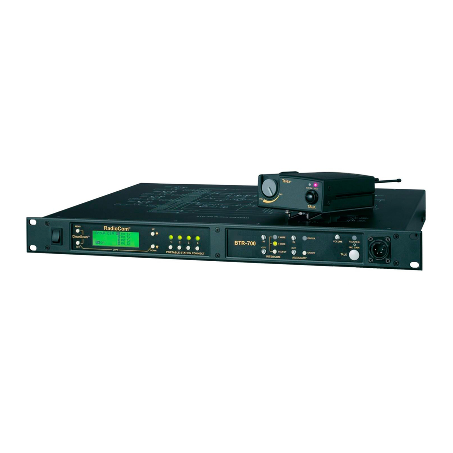
Telex RadioCom BTR-700 Operating Instructions Manual
Professional wireless intercom system
Hide thumbs
Also See for RadioCom BTR-700:
- Supplementary manual (1 page) ,
- Operating instructions manual (68 pages) ,
- Operating instructions manual (65 pages)

Related Manuals for Telex RadioCom BTR-700


Summary of Contents for Telex RadioCom BTR-700
- Page 1 Telex Op er ating In struc tions RadioCom ™ BTR-700, TR-700 Pro fes sional Wire less 0885 In ter com Sys tem 0891...
- Page 2 Thank you for choos ing RadioCom™ Telex Com mu ni ca tions would like to take this op por tu nity to thank you for choos ing the RadioCom™ BTR-700 Pro fes sional Wire less In ter com Sys tem. Many of the fea tures in this prod uct are the re sult of years of de vel op - - ment work with many of the fea tures de vel oped from cus tomer feed back.
-
Page 3: Table Of Contents
Ta ble of Con tents In tro duc tion ................Gen eral De scrip tion . - Page 4 Ta ble of Con tents (con tin ued) Beltpack Op er a tion ............... . 6-11 Power/Lo cal Head set Vol ume.
-
Page 5: In Tro Duc Tion
AA al ka line bat ter ies. RTS® and Audiocom® are reg is tered trade marks of Telex Com mu ni ca tions, Inc. Clear-Com® is a reg is tered trade mark of Clear-Com In ter com Sys tems, Inc. -
Page 7: Btr-700 Base Sta Tion
12. Lo cal Head set Con nec tor – Male XLR con nec tor for Telex units, Fe male XLR con nec tor for RTS units. A dy - 5. Por ta ble Sta tion Con nect – But tons used to en able or namic or electret head set mi cro phone is au to mat i cally de - dis able the re spec tive re ceiver’s au dio. -
Page 8: Con Trols And Con Nec Tions - Rear Panel
4. I/C Se lect Switch – Set to the ap pro pri ate 2-wire in ter com loop thru ports will dam age the in ter com! type be ing in ter faced to the unit. Set to ei ther Telex, RTS Do not ex ceed 200 mA cur rent in the 2 or Clear-Com®. -
Page 9: Btr-700 Specifications
Telex In ter com....In put/Out put Level Ad just able (1 Vrms typ i cal), Line im ped ance 300... - Page 10 2-4 Blank...
-
Page 11: Con Trols And Con Nec Tions - Top Panel
TR-700 Beltpack Con trols and Con nec tions - Top Panel Telex BAT/OM TALK TALK Fig ure 4 TR-700 Top Panel 1. On/Off & Vol ume Con trol – Turns the beltpack power 3. Talk Light – LED is on when the talk but ton is ac tive. -
Page 12: Con Trols And Con Nec Tions - Rear Panel
Con trols and Con nec tions - Rear Panel 6. Head set Con nec tor – Male XLR con nec tor for Telex units, Fe male XLR con nec tor for RTS units. A dy namic or electret head set mi cro phone is au to mat i cally de tected by the beltpack and a bias volt age sup plied if needed. -
Page 13: Tr-700 Spec I Fi Ca Tions
TR-700 Spec i fi ca tions RF Fre quency Range..518 - 608 MHz, 614 - 740 MHz, 796 - 868 MHz in 18 MHz TX and RX bands Power Re quire ments........6 “AA” Cells Al ka line (NiMH op tional) Cur rent Draw . - Page 14 3-4 Blank...
-
Page 15: Ini Tial Equip Ment Set-Up
Fill out the reg is tra tion card and re turn it to Telex to reg is ter the unit. Quan tity De scrip tion... -
Page 16: An Tenna Con Nec Tions
Attaching Receive 1/2-Wave An tenna An tenna Po lar iza tion The Telex Wire less In ter com Sys tem is “Ver ti cally Po lar ized”. Fig ure 10 This means both the trans mit ting and re ceiv ing an ten nas Proper Dress ing of the An tennas should op er ate in the ver ti cal po si tion. - Page 17 Keep the dis tance be tween the base sta tion and the beltpacks At tempting to op er ate the wire less in ter com sys tem through or as short as pos si ble. The greater the dis tance, the weaker the around walls, ceil ings, metal ob jects, etc.
-
Page 18: Im Proving Re Cep Tion/In Creasing Range
2. Placing the BTR on top of a shelf or equip ment rack un - ob structed with out remoting the an ten nas is OK. 3. Placing BTRs in a shelf or equip ment rack with the an - 1. -
Page 19: Base Sta Tion Set-Up
AUXILIARY AUDIO 100-240 VAC 50-60 Hz FCC ID: B5DM516 2 WIRE PUSH PUSH CANADA 1321231218A TRANSMIT POWER 4 WIRE HIGH NORM TELEX COMMUNICATIONS INC. TRANSMIT MADE IN USA TELEX CLEARCOM INPUT OUTPUT POWER TRANSMIT SWITCHES INTERCOM SWITCH Fig ure 15... -
Page 20: In Ter Com Switch
In ter com In ter face The Radiocom™ wire less sys tem can be in ter faced to RTS Telex (Audiocom®) and Clear-Com® in ter com sys tems re - - TW, Audiocom® (Telex), Clear-Com®, RTS ma trix and other quire one ca ble for in ter com. -
Page 21: Aux Il Iary In Put/Out Put
BTR-700 RECEIVE INTERCOM AUXILIARY AUDIO BP-318 100-240 VAC 50-60 Hz FCC ID: B5DM516 2 WIRE PUSH PUSH TRANSMIT CANADA 1321231218A POWER TELEX COMMUNICATIONS INC. 4 WIRE MADE IN USA TRANSMIT HIGH NORM TELEX CLEARCOM INPUT OUTPUT POWER BTR-700 HEADSET LINE... -
Page 22: Beltpack Set-Up
Beltpack Set-up Bat tery In stal la tion En sure that the On/Off vol ume con trol knob is turned off. Press down and hold down the bat tery re lease latch, slide the bat tery pack about 1/8 inch back, to ward the latch, un til it stops. -
Page 23: An Tenna Con Nec Tion
- - sec tion if this is not a Telex head set. A dy namic or electret ta cle. The lon gest an tenna is the re ceiver an tenna. It screws... - Page 24 4-10 Blank...
-
Page 25: Pre-Walk-Thru Check List
ection Pre-Walk-Thru Check list Fol low ing the in struc tions fully to this point you have suc cess - - fully com pleted the fol low ing check list: Lo cated the base sta tion prop erly. Con nected head sets to base sta tions (if needed) and all beltpacks. - Page 26 5-2 Blank...
-
Page 27: System Op Er A Tion
ection System Op er a tion Fre quency Plan Over view Sys tem Quick Start The BTR/TR-700 has 36 fac tory de fined fre quency groups and 12 user-programmable fre quency groups. A Group de - - Fol low the list be low to quickly get a base sta tion and fines the base sta tion trans mit fre quen cy and thus the re ceive beltpack(s) op er at ing. -
Page 28: Base Sta Tion Op Er A Tion
Set the base sta tion power switch to the on po si tion, by push - - tem, such as Audiocom (Telex), RTS TW or Clear-Com®, ing the top of the switch.The in ter nal cool ing fan will start im - - set the in ter com to 2-wire. -
Page 29: Dis Play Con Trast
Dis play Con trast The LCD’s (Liq uid Crys tal Dis play) con trast is set from the fac tory to a stan dard level. How ever it is pos si ble for the user to ad just the con trast if de sired. The con trast con trol is in ter - - nal to the BTR-700 unit near the front panel. -
Page 30: Main Screen Flowchart
The fol low ing con tains the base station menu struc ture and ref er ences the pages in which fur ther de tail of that menu may be found. Power-Up Screen - Pg. 6-5 Telex S S B20001 C60001 RadioCom [MENU] Operating Screen - Pg. -
Page 31: Power-Up Screen
Power-Up Screen Power-Up Screen • This screen is dis played only on power-up, first use de - Telex B20001 fault, and fac tory de fault. C60001 RadioCom • The 1 up per right cor ner num ber dis plays the base’s soft - ware re vi sion. -
Page 32: Group/Chan Nel Se Lect
Group / Channel Select Group / Chan nel Se lect The Group/Chan nel se lect screen al lows the user to change the group and se lect from a pre-determined num ber of chan nels Group 14 Ch 01 on each re ceiver. Ch 02 Ch 03 •... -
Page 33: Group/Fre Quency Se Lect
Group / Fre quency Se lect Group / Frequency Select The Group/Fre quency se lect screen al lows a user to set the group and se lect from a pre-determined num ber of fre quen cies Group 15 715.000 on each re ceiver. Each fre quency dis played on the right half of 716.700 the screen corresponds to a chan nel num ber in the Group/Chan nel Screen. -
Page 34: Fre Quency Edit
Fre quency Edit Fre quency Edit (User-Programmed Groups Only) (User-Programmed Groups Only) This menu only oc curs for user-programmable groups or when copy ing to a user-programable group. The Fre quency Edit screen al lows the user to set the group trans mit fre quen cy and re ceive chan nel fre quen cies of a user-programmable group. -
Page 35: Clearscan
To achieve the best re sults quickly when us ing ClearScan, ClearScan please com plete the fol low ing for set ting up a sin gle BTR-700 sys tem: ClearScan per forms a fre quency scan of the fac tory -de fined and any set-up user-programmable groups in or der to find the group with the high est num ber of clear re ceive chan nels. -
Page 36: Spe Cial Key Se Quences
Spe cial Key Se quences Lock out Use De fault • • Press [UP]+[DOWN] for 3 sec onds to lock or un lock the Press [MENU] while turn ing on the base sta tion to en ter the 1 use de fault setup screen. This places the unit on base sta tion. -
Page 37: Beltpack Op Er A Tion
Beltpack Op er a tion POWER BATTERY LOCAL HEADSET VOLUME CHECK Telex BAT/OM TALK TALK BUTTON TALK MICROPHONE GAIN Fig ure 21 TR-700 - Top and Rear Panel Talk But ton Power / Lo cal Head set Vol ume Press the talk but ton to en able the au dio path from the head set Turn the beltpack power on by ro tat ing the knob CW. -
Page 38: Beltpack Menu Struc Ture
TR-700 Menu Struc ture Beltpack Menu Struc ture The fol low ing con tains the main beltpack menu struc ture and ref er - - ences the pages in which fur ther de tail of that menu may be found. All beltpack fea tures and spe cial key se quences can only be done from the group/channel screen. -
Page 39: Power-Up Screens
Power-Up Screens Power-Up Screens • The first screens dis played when the beltpack is pow ered up are the soft ware and chan nel map ver sion screens. S20001 • The 1 screen dis played in di cates the beltpack’s soft ware ver sion num ber. -
Page 40: Group/Chan Nel Screen
Group / Chan nel Screen Group / Chan nel Screen The Group/Chan nel screen al lows the user to change the group and se lect from a pre-determined num ber of trans mit chan nels. 03A 01 03A 01 • The screen dis played af ter the beltpack pow er-up screens. -
Page 41: Trans Mit Screen
Trans mit Screen Trans mit Screen The Transmit screen al lows the user to set the beltpack trans - - mit fre quency. Fac tory-defined groups will al low only a set num ber of pre-defined fre quen cies to be se lected. User-programmable groups will al low the user to change the fre quency in 25kHz steps. -
Page 42: Re Ceive Screen
Re ceive Screen Re ceive Screen The Receive screen al lows the user to set the beltpack re ceive fre quency. This cor re sponds to the base sta tion’s trans mit fre - - quency. In fac tory-defined groups re ceive is not change able. User-programable groups will al low the user to change the fre quency in 25 KHz steps. -
Page 43: Clearscan
ClearScan™ ClearScan™ ClearScan™ per forms a fre quency scan of the fac tory-defined and any set-up user-programmable groups in or der to find the clear est group. Af ter about 30 sec onds, the clear est group is dis played. A group is de fined by the re ceive fre quen cy. The next best group and so forth may be ac cessed with the [DOWN] and [UP] ar row but tons. -
Page 44: Talk But Ton Latch On/Latch Off
Talk But ton Latch on/Latch off HOLD [SET] AND PRESS [TALK] • Press and hold [SET] then press the [TALK] but ton to show the Talk But ton Latch/Non-Latching screen. The cur rent set ting of the fea ture is dis played on the LCD dis - play. -
Page 45: Sys Tem Walk-Thru
In 99% of all in stances you will set up your Telex Wire less In - - Check that the talk but ton is en gaged. The talk LED ter com Sys tem, walk it through the area of in ter est and will be il lu mi nated. - Page 46 7-2 Blank...
-
Page 47: Trou Ble Shooting
Make sure that all the Telex beltpack(s) are on. If there are any unused receivers at the base, turn the audio off from those receivers by deselecting the appropriate “Portable INTERFERENCE - System picks up signals other than Station Connect”... - Page 48 8-2 Blank...
-
Page 49: Tech Tips
The mi cro phone gain lected by Telex for this RadioCom™ sys tem are cho sen to must be re duced. The same ap plies to a user with a pow er ful min i mize pos si ble in ter fer ence. - Page 50 9-2 Blank...
-
Page 51: Bat Tery Information
ection Bat tery Information Im proper bat tery se lec tion, use, in stal la tion and care are the Bat tery Life: cause of nu mer ous wire less sys tem fail ures. TR-700 Al ka line Bat teries: Al ka line bat ter ies such as Mallory’s Al ka line, 12-14 Hours DURACELL®... - Page 52 10-2 Blank...
- Page 53 Send: ........20kHz 100 Hz, 240 mVrms Re ceive: ......20kHz 800 Hz, 100 mVrms MALE Power Volt age: ..........28.0 VDC nom i nal AudioCom/Telex COMMON In put Im ped ance: ..............300 AUDIO ( - ) PLUS POWER Out put Level:..........1.0 Vrms nom i nal Bridg ing Im ped ance: ............>10k...
- Page 54 11-2 Blank...
-
Page 55: Ac Ces Sories And Re Place Ment Parts
CXU-50 50 Ft. (15 meter) 71151-050 BTR In ter com Dummy Load CXU-75 75 Ft. (23 meter) 71151-075 Telex type............PN 878935 RTS type ............PN 878990 CXU-100 100 Ft. (30 meter) 71151-100 TR LCD/ switch cover ..........PN 450364 Base Sta tion:... - Page 56 Ac ces so ries and Re place ment Parts (con tin ued) BP-700 TR Bat tery pack, al ka line (bat ter ies not in cluded)........PN 71315-000 BP-800NM TR Nickel Metal Hy dride 2200mAh Bat tery pack ..........PN 71315-002 BC-800NM4 Four Slot “Smart”...
-
Page 57: Soft Ware Li Cense
IM POR TANT - Please red this doc u ment care fully be fore us ing this prod uct. THIS DOC U MENT STATES THE TERMS AND CON DI TIONS UPON WHICH TELEX COM MU NI CA TIONS, INC. (the “COM PANY”) OF FERS TO LI CENSE THE IN STALLED SOFT WARE OR PRO GRAM (the “SOFT WARE”) FOR USE... - Page 58 13-2 Blank...
-
Page 59: Certification In For Ma Tion
Com mis sion Part 74. Li cens ing of Telex equip ment is the User’s re spon si bil ity and licensibility de pends on the user’s clas si fi ca tion, us ers ap pli ca tion, and fre quency se lected. Telex strongly urges the user to con tact the ap pro pri ate tele com mu ni ca tions au thor ity for any de sired clar i fi ca tion. - Page 60 Li cens ing of Telex equip ment is the us ers re spon si bil ity and licensability de pends upon the user's clas si fi ca tion, user's ap pli ca tion and fre quency se lected. Telex strongly urges the user to con tact the ap pro pri ate tele com mu ni ca tions au thor ity for any de sired clar i fi ca tion.
- Page 61 14-3...
- Page 62 14-4...
- Page 63 • BOSCH SE CU RITY SYS TEMS 12000 Port land Ave. South, Burnsville, MN 55337. PN 803290-2 REV H FEB 2010 Made in U.S.A.
Need help?
Do you have a question about the RadioCom BTR-700 and is the answer not in the manual?
Questions and answers