Telex TR-700 Quick Start Card
Telex tr-700 intercom system: quick start
Hide thumbs
Also See for TR-700:
- Operating instructions manual (68 pages) ,
- Operating instructions manual (65 pages) ,
- Operating instructions manual (63 pages)
Advertisement
TR-700 Quick Start Card
Initial Beltpack and Base Station Set-up
1. Press [MENU] as powering-up the base station. This will place it on group 01A and set
the receives on channels: 01, 02 , 03 and 04. Ensure the appropriate portable station
connect path is enabled. If used stand alone, the base should be in the 4-wire mode.
2. Set beltpack back panel slide switch to push-to-talk (PT TALK).
3. Press [MENU] as powering-up the beltpack. This will place the beltpack on group
01A with channel 01 flashing.
4. Use the [UP] and [DOWN] arrow buttons to change the channel to an unoccupied receive
channel on the base station. Then press [SET]. Press [MENU] if not changing channels.
5. The group/channel on the beltpack should now match the group and a receive channel
on the base station. Nothing should be flashing on the beltpack screen.
6. Plug a headset into the beltpack and set the microphone gain so the BAT/OM light
flashes at the beginning of most words at normal speech levels.
Special Functions
ClearScan· · · · · · · Press [MENU]+[SET] buttons for 3 seconds. After 25 seconds of
searching, the beltpack will produce a list of the groups organized
from best (clearest) to worse. The best group is displayed
flashing. Use the [UP] and [DOWN] buttons to select other
groups if desired.
Lockout · · · · · · · · Press [UP]+[DOWN] arrows buttons for 3 seconds. Repeat to
toggle it off/on.
st
1
Use Default · · · Press [MENU] as powering-up the beltpack. Sets beltpack on
group 01A with channel 01 flashing. User must then set the
channel. All user-programmed memory is retained.
Factory Default · · Press [MENU]+[SET]+[UP]+[DOWN] buttons for 3 seconds to
software "reset" the beltpack. All user-programmed memory is erased.
Talk Latch Enable/Disable
Talk Button . . . . . . . . . . . . . . . . Press and hold [SET] then press [TALK] to enable
latching or non-latching.
latching or non-latching.
1
2
3
4
5
1. [MENU] and [SET] buttons – Used to select menus and set options on the LCD.
2. LCD display.
3. [UP] and [DOWN] buttons – Used to select beltpack options on the LCD.
4. Microphone Gain – Adjusts the headset's microphone gain. Adjust so that the light
flashes at the beginning of most words at normal speech levels.
5. Push-to-Talk/Push-to-Transmit Switch –
Push-to-Talk (PT TALK) – The transmitter is always on. No audio sent
unless the talk button is pressed. Recommended position.
Push-to-Transmit (PT TX) - The transmitter and audio path are off except
when the talk button is pressed.
6. Headset Connector – Male XLR connector for Telex units, Female XLR connector
for RTS units.
7. Battery Latch – Press down to enable the battery pack to be released. While the latch
is held down, slide the battery pack about 1/8 inch back, toward the latch, until it stops,
then lift out.
8. Receive Antenna – Screw type ¼ wave replaceable antenna. The receiver antenna is
always the longer antenna. Color dot on the screw end of the antenna must match color
dot on antenna receptacle.
9. Transmit Antenna – Screw type ¼ wave replaceable antenna. Color dot on the screw
end of the antenna must match color dot on antenna receptacle.
6
7
8
9
6
7
8
9
Advertisement
Table of Contents

Related Manuals for Telex TR-700


Summary of Contents for Telex TR-700
- Page 1 Push-to-Transmit (PT TX) - The transmitter and audio path are off except when the talk button is pressed. 6. Headset Connector – Male XLR connector for Telex units, Female XLR connector for RTS units. 7. Battery Latch – Press down to enable the battery pack to be released. While the latch is held down, slide the battery pack about 1/8 inch back, toward the latch, until it stops, then lift out.
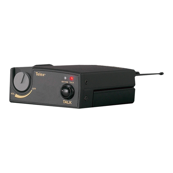
- Page 2 Telex 1. On/Off & Volume Control - Turns the beltpack power on and controls headset volume. 2. Bat/Overmod Light - LED will flash once when unit is turned on if the battery is good. If the light stays on, battery is low. If the light does not flash, battery is dead.
Need help?
Do you have a question about the TR-700 and is the answer not in the manual?
Questions and answers