
Related Manuals for Telex BTR-24


Summary of Contents for Telex BTR-24
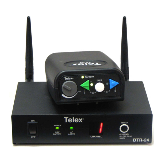
- Page 1 Operating Manual BTR-24 TR-24 Wireless Intercom System Bosch Communications Systems...
-
Page 2: Table Of Contents
BTR-24 Base Station ........ -
Page 3: Section 1 - Introduction
The beltpack uses an internal rechargeable Li-Ion battery that will provide up to 8 hours of uninterrupted operation. The BTR-24 base station can support up to ten TR-24 beltpacks in full duplex mode and more if in push-to-transmit mode. The base station provides a central relay location which handles the audio traffic between beltpacks. -
Page 4: Section 2 - Btr-24 Base Station
Section 2 - BTR-24 Base Station Telex POWER BATTERY ACTIVE CHANNEL Front View 1. On/Off Switch – Turns the power on/off to the base station. 2. Power / Low Battery Light – Indicates the base station has power, either from the internal battery or external power connected to the unit. -
Page 5: Beltpack
Section 3 - TR-24 Beltpack 1 2 3 S.T. Top View 1. Volume Control and Power Switch – Turns the beltpack power on/off and controls headset volume. 2. Battery Light/Power Light – Indicates the beltpack has power, either from the internal battery or AC power connected to the unit. -
Page 6: Section 4 - Specifications
TR-24 Recharge Time...6-8 Hr (Typical) TR-24 Low Battery Indication...15 minutes of battery life left (Typical) BTR-24 (Base Station)Size...6.00” L x 7.63” W x 1.72” H (15.24cm x 19.37cm x 4.37cm) BTR-24 Weight...2 lb 11 oz (1.2 kg) TR-24 Size ...5.25” L x 3.75” W x 1.68” H (13.33cm x 9.53cm x 4.27cm) TR-24 Weight...12.5oz (354g) -
Page 7: Section 5 - Operation
TR-24 Telex POWER SELECT BATTERY ACTIVE CHANNEL CHANNEL CLEAR SCAN LOCK BTR-24 Telex TR-24 Telex TR-24 Telex TR-24 Figure 5-1 Ten Beltpacks in Wireless Mode With ten beltpack in full duplex, up to 28 additional beltpacks can work off the base station if these beltpacks are in Push-to-TX mode. -
Page 8: Set-Up
POWER BATTERY ACTIVE 1. Prior to use the TR-24 and BTR-24 should have their battery packs fully charged. Refer to the “Battery Charging Instructions” near the end of this section. 2. Plug the BTR-24's external power supply into an AC outlet if available. -
Page 9: Wired Mode
(Push-to-TX) enables the audio path for only as long as it is held down. The beltpack will be in this mode until reset push-to-latch mode. Telex Telex BATTERY BATTERY TALK TALK Figure 5-5 Top View of TR-24 The sidetone (amount of your own voice fed back to your earphones) and microphone gain of the beltpacks may need adjusted from the factory defaults. -
Page 10: Set-Up
Ethernet network. In fact do to the flexibility of the BTR-24 system, wired beltpacks connected via a hub to a network could communicate to a BTR-24 connected to the same network. This base station could then be connected wirelessly to other TR-24s operating in wireless mode. -
Page 11: Network Requirements
Ethernet networked devices. These rules are: 1. All TR-24s and BTR-24 must have unique IP (Internet Protocol) addresses. This means no TR-24s or BTR-24s in a network should have the same IP address. Also, no other devices on the wired network should have the same IP addresses as the BTR-24s and TR-24s to be used. -
Page 12: System Operation
2. Plug the master TR-24’s external power supply into an AC outlet if desired. If external power is not desired then run off internal battery. 3. Place the TR-24’s in a location where it will have the best visibility to the other TR-24s. 4. -
Page 13: Tour Group Example
Charge the BTR-24 and TR-24 internal battery as follows: 1. Ensure the TR-24 beltpacks are in the “OFF” position. 2. Ensure the BTR-24 base stations are in the “OFF” position. 3. TR-24 beltpack: Plug the charger into the charge jack on the bottom of the beltpack. -
Page 14: Encryption Code
Login: telex • Password: legacy The login of "telex" cannot be changed, but for increased security the password can be changed via the user menu. Please see the "Logging into a Unit" instructions in this section for details on changing the password. -
Page 15: User Menu Options
This option allows the user to change this TR-24’s password. The default from the factory is legacy. The user is never allowed to change the login name of telex. 2. Display current encryption Key Displays on the screen the current encryption key of the beltpack. -
Page 16: Section 7 - Battery Care/Long Term Storage
To ensure the long life and safe handling of the Li-Ion battery within the BTR-24 and TR-24 please following the following precautions: 1. Store the TR-24s and BTR-24 in a clean, cool, dry location away from heat. 2. Do not store for extended periods of time in direct sunlight. - Page 17 The unit will do a clear scan and place itself on the clearest channel. The beltpacks do not have to be turned off, they will follow the BTR-24 to the new channel within a few seconds after the clear scan is done.
- Page 18 25 seconds. Can't change the RF channel the BTR-24 is When the TR-24 beltpack power was turned on, the unit's power light came up, but the "1"...
-
Page 19: Rf Channels
802.11 RF Channels The BTR-24 system has the ability to operate on any one of eleven RF channels. Although there are several different frequency channel settings, there is overlap between the channels. There are three non-overlapping channels available in the FCC regulatory domain. When choosing frequency channels for systems in the vicinity of each other, you should choose frequency channels that do not overlap (e.g. -
Page 20: Regulatory Information
Section 10 - Regulatory Information Regulatory Information The TR-24 and BTR-24 comply with Part 15 of FCC rules and Canada RSS-210. Operation is subject to the following conditions: 1. This device may not cause harmful interference. 2. This device must accept any interference received, including interference that may cause undesired operation. -
Page 21: Part Number
10 ft. coax with TNC reverse polarity plug 302054008 connector. TNC reverse polarity coupler. Coupler is a 302054009 reverse polarity jack to jack. Carry Case for BTR-24 System. 302054010 Omni Antenna (3dB) with TNC reverse 302054003 polarity connector. Omni Antenna (7dB) with TNC reverse 302054004 polarity connector. - Page 22 Model Number BTR-24 SYS-243 ANT-FP ANT-FPM LG-PS Part Number BTR-24 Base Station and US power PRD000066000 supply. NOTE: User must provide IP address of all TR-24/BTR-24's in system with order. System includes Carry Case, 3 TR-24 SYS000007000 Beltpacks, 1 BTR-24 Base Station, Omni antennas, rack mounts, 3' Ethernet cable, and US power supplies.
- Page 23 Bosch Communications Systems 8601 East Cornhusker Highway, Lincoln, NE 68507 Made in U.S.A. PN LIT000078TX Rev. A...
Need help?
Do you have a question about the BTR-24 and is the answer not in the manual?
Questions and answers