
Related Manuals for Telex RadioCom BTR-800-H1


Summary of Contents for Telex RadioCom BTR-800-H1
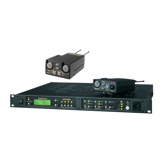
- Page 1 Telex Op er ating In struc tions RadioCom ™ BTR-800, TR-800, TR-825 Pro fes sional Wire less In ter com Sys tem 0891...
- Page 2 Thank you for choos ing RadioCom Telex Com mu ni ca tions would like to take this op por tu nity to thank you for choos ing the RadioCom™ BTR-800 Pro fes sional Wire less In ter com Sys tem. Many of the fea tures in this prod uct are the re sult of years of de vel op - - ment work with many of the fea tures de vel oped from cus tomer feed back.
-
Page 3: Table Of Contents
Ta ble of Con tents In tro duc tion ................Gen eral De scrip tion . - Page 4 Ta ble of Con tents (con tin ued) TR-800 Beltpack Op er a tion ..............7-11 Power/Lo cal Head set Vol ume.
-
Page 5: In Tro Duc Tion
Base sta tion co mes with rack ears for easy rack mount ing. RTS® and Audiocom® are reg is tered trade marks of Telex Com mu ni ca tions, Inc. Clear-Com® is a reg is tered trade mark of Clear-Com In ter com Sys tems, Inc. -
Page 7: Btr-800 Base Sta Tion
Au dio in put and out put level con trols. 2-wire or Telex units, Fe male XLR con nec tor for RTS units. A dy - 4-wire se lect but ton with green LED in di ca tor lights. Se - namic or electret head set mi cro phone is au to mat i cally de - tected. -
Page 8: Con Trols And Con Nec Tions - Rear Panel
4. I/C Se lect Switch – Set to the ap pro pri ate 2-wire in ter com ex ceed 200 mA cur rent in the 2 wire loop type be ing in ter faced to the unit. Set to ei ther Telex, RTS thru curcuits. -
Page 9: Btr-800 Spec I Fi Ca Tions
Telex In ter com....In put/Out put Level Ad just able (1 Vrms typ i cal), Line im ped ance 300... - Page 10 2-4 Blank...
-
Page 11: Con Trols And Con Nec Tions - Top Panel
TR-800 Beltpack Con trols and Con nec tions - Top Panel Telex BAT/OM TALK CHANNEL TALK Fig ure 4 TR-800 Top Panel 1. On/Off & Vol ume Con trol – Turns the beltpack power on and con trols head set vol ume. -
Page 12: Con Trols And Con Nec Tions - Rear Panel
Con trols and Con nec tions - Rear Panel 6. Head set Con nec tor – Male XLR con nec tor for Telex units, Fe male XLR con nec tor for RTS units. A dy namic or electret head set mi cro phone is au to mat i cally de tected by the beltpack and a bias volt age sup plied if needed. - Page 13 TR-800 Spec i fi ca tions RF Fre quency Range ..... . 470 - 608 MHz, 614 - 740 MHz in 18 MHz TX and RX bands Power Re quire ments.
- Page 14 3-4 Blank...
-
Page 15: Con Trols And Con Nec Tions - Top Panel
Con trols and Con nec tions - Top Panel BAT/OM TALK TALK Telex Fig ure 7 TR-825 Top Panel 1. On/Off and Vol ume Con trol - Turns beltpack power on 4. Talk But ton - Press to en able the au dio path to ei ther In - and con trols head set vol ume for In ter com Chan nels “A”... -
Page 16: Con Trols And Con Nec Tions - Rear Panel
These head sets must have the beltpack set for [Ab SEP] 6. Head set Con nec tor – Male XLR con nec tor for Telex units, Fe male XLR con nec tor for RTS units. A dy namic or 7. - Page 17 TR-825 Spec i fi ca tions RF Fre quency Range ..... . 470 - 608 MHz, 614 - 740 MHz in 18 MHz TX and RX bands Power Re quire ments.
- Page 18 4-4 Blank...
-
Page 19: Ini Tial Equip Ment Set-Up
Fill out the reg is tra tion card and re turn it to Telex to reg is ter the unit. Quan tity De scrip tion... -
Page 20: An Tenna Con Nec Tions
Attaching Re ceive 1/2-Wave An tenna An tenna Po lar iza tion The Telex Wire less In ter com Sys tem is “Ver ti cally Po lar ized”. This means both the trans mit ting and re ceiv ing an ten nas Fig ure 13 should op er ate in the ver ti cal po si tion. - Page 21 Keep the dis tance be tween the base sta tion and the beltpacks At tempting to op er ate the wire less in ter com sys tem through or as short as pos si ble. The greater the dis tance, the weaker the around walls, ceil ings, metal ob jects, etc.
-
Page 22: Im Proving Re Cep Tion/In Creasing Range
2. Placing the BTR on top of a shelf or equip ment rack un - ob structed with out remoting the an ten nas is OK. 3. Placing BTRs in a shelf or equip ment rack with the an - 1. -
Page 23: Base Sta Tion Set-Up
STAGE ANNOUNCE TRANSMIT BASE STATION POWER LINK 4 WIRE 4 WIRE RELAY CONTACT Telex TRANSMIT HIGH NORM Telex Communications, Inc. TELEX CLEARCOM MADE IN USA INPUT OUTPUT OUTPUT POWER TRANSMIT SWITCHES INTERCOM SWITCH Fig ure 18 Base Sta tion - Rear Panel... -
Page 24: In Ter Nal Trans Mit Switches
In ter com In ter face BACK Telex (Audiocom®) and Clear-Com® in ter com sys tems re - - quire one ca ble for in ter com A and one ca ble for in ter com B in or der to in ter face two chan nels of in ter com to the base sta tion. - Page 25 PUSH STAGE ANNOUNCE TRANSMIT BASE STATION POWER LINK 4 WIRE 4 WIRE RELAY CONTACT Telex HIGH HIGH NORM NORM TRANSMIT Telex Communications, Inc. TELEX CLEARCOM MADE IN USA INPUT OUTPUT OUTPUT POWER BTR-800 HEADSET LINE BP-350 HEADSET LINE BP-350 TR-800’s TR-825’s...
-
Page 26: Dual Lis Ten Func Tion Al Ity
750608 and nents, how ever, mod i fi ca tion doc u ments may be ob tained ASY000108000. from Telex Com mu ni ca tions for those who wish to mod ify older au dio boards for dual lis ten. BACK... -
Page 27: Aux Il Iary In Put/Out Put
B. How ever, there is an is avail able from Telex Communications for those who wish to in ter nal switch to con trol the rout ing of the in put aux il iary au - - mod ify the base sta tion so that aux il iary in put au dio is heard only lo cally;... -
Page 28: Stage An Nounce /Re Lay Con Tacts
BASE STATION POWER LINK 4 WIRE 4 WIRE RELAY CONTACT Telex HIGH NORM TRANSMIT Telex Communications, Inc. TELEX CLEARCOM MADE IN USA INPUT OUTPUT OUTPUT POWER STAGE ANNOUNCE STAGE ANNOUNCE RELAY Base Sta tion - Rear Panel Stage An nounce / Re lay Con tacts... -
Page 29: Base Sta Tion Link
POWER LINK 4 WIRE 4 WIRE RELAY CONTACT Telex HIGH NORM TRANSMIT Telex Communications, Inc. TELEX CLEARCOM POWER MADE IN USA INPUT OUTPUT OUTPUT Base Sta tion - Rear Panel Base Sta tion Link A ca ble to ac com plish this task is NOT sup plied, but can eas - - This RJ-45 type jack al lows the con nec tion of wire less talk ily be made with com mon cat e gory 5 (CAT-5) wir ing. -
Page 30: Beltpack Set-Up
Beltpack Set-up Bat tery In stal la tion En sure that the On/Off vol ume con trol knob is turned off. Press down and hold down the bat tery re lease latch, slide the bat tery pack about 1/8 inch back, to ward the latch, un til it stops. -
Page 31: An Tenna Con Nec Tion
The color dot on the nec tions” sec tion if this is not a Telex head set. A dy namic or screw end of the an tenna must match the color dot on an tenna electret head set mi cro phone is au to mat i cally de tected by the re cep ta cle. - Page 32 5-14 Blank...
-
Page 33: Pre-Walk-Thru Check List
ection Pre-Walk-Thru Check list Fol low ing the in struc tions fully to this point you have suc cess - - fully com pleted the fol low ing check list: Lo cated the base sta tion prop erly. Con nected head sets to base sta tions (if needed) and all beltpacks. - Page 34 6-2 Blank...
-
Page 35: System Op Er A Tion
1A and 1B, have dif fer ent base sta tion transmit fre quen - - panel IC A and B is in 2-wire for AudioCom (Telex), RTS cies, how ever, they both have the same eight base station re - - -TW and ClearCom wired sys tems, and 4-wire for RTS ceive chan nels from which to choose. -
Page 36: Base Sta Tion Op Er A Tion
Set the base sta tion power switch to the on po si tion, by push - - tem, such as Audiocom (Telex), RTS TW or Clear-Com®, ing the top of the switch.The in ter nal cool ing fan will start im - - set the in ter com to 2-wire. -
Page 37: Dis Play Con Trast
Dis play Con trast The LCD’s (Liq uid Crys tal Dis play) con trast is set from the fac tory to a stan dard level. How ever it is pos si ble for the user to ad just the con trast if de sired. The con trast con trol is in ter - - nal to the BTR-800 unit near the front panel. -
Page 38: Main Screen Flowchart
The fol low ing con tains the base station menu struc ture and ref er ences the pages in which fur ther de tail of that menu may be found. Power-Up Screen - Pg. 7-5 Telex SB10001 C60001 RadioCom [MENU] Operating Screen - Pg. -
Page 39: Power-Up Screen
Power-Up Screen Power-Up Screen • This screen is dis played only on power up, first use de - Telex SB10001 fault and fac tory de fault. C60001 RadioCom • The 1 up per right cor ner num ber dis plays the base’s soft - ware re vi sion. -
Page 40: Group/Chan Nel Se Lect
Group / Channel Select Group / Chan nel Se lect The Group/Chan nel se lect screen al lows the user to change the group and se lect from a pre-determined num ber of chan nels Group 14 Ch 01 on each re ceiver. Ch 02 Ch 03 •... -
Page 41: Group/Fre Quency Se Lect
Group / Fre quency Se lect Group / Frequency Select The Group/Fre quency se lect screen al lows a user to set the group and se lect from a pre-determined num ber of fre quen cies Group 15 715.000 on each re ceiver. Each fre quency dis played on the right half of 716.700 the screen corresponds to a chan nel num ber in the Group/Chan nel Screen. -
Page 42: Fre Quency Edit
Fre quency Edit Fre quency Edit (User-Programmed Groups Only) (User-Programmed Groups Only) This menu only oc curs for user-programmable groups or when copy ing to a user-programable group. The Fre quency Edit screen al lows the user to set the group trans mit fre quen cies and re ceive chan nel fre quen cies of a user-programmable group. -
Page 43: Clear Scan
To achieve the best re sults quickly when us ing ClearScan, ClearScan™ please com plete the fol low ing for set ting up a sin gle BTR-800 sys tem: ClearScan™ per forms a fre quency scan of the fac tory-defined and any set-up user-programmable groups in or der to find the group with the high est num ber of clear re ceive chan nels. -
Page 44: Spe Cial Key Se Quences
Spe cial Key Se quences Lock out Use De fault • • Press [UP]+[DOWN] for 3 sec onds to lock or un lock the Press [MENU] while turn ing on the base sta tion to en ter the 1 use de fault setup screen. This places the unit on base sta tion. -
Page 45: Bat Tery Check
Beltpack Op er a tion WIRELESS TALK AROUND (WTA) ON/OFF and BATTERY CHECK VOLUME CONTROL Telex BAT/OM TALK TR-800 TALK BUTTON CHANNEL TALK AUDIO CHANNEL STAGE ANNOUNCE SELECT BUTTON (SA) MICROPHONE GAIN WIRELESS TALK AROUND (WTA) STAGE ANNOUNCE (SA) TR-825... - Page 46 TR-800 Menu Struc ture Beltpack Menu Struc ture The fol low ing con tains the main beltpack menu struc ture and ref er - - ences the pages in which fur ther de tail of that menu may be found. All beltpack fea tures and spe cial key se quences can only be done from the group/channel screen.
-
Page 47: Power-Up Screens
TR-800 Menu Struc ture Power-Up Screens Power-Up Screens • The first screens dis played when the beltpack is pow ered up are the soft ware and chan nel map ver sion screens. S10001 • The 1 screen dis played in di cates the beltpack’s soft ware ver sion num ber. -
Page 48: Group/Chan Nel Screen
TR-800 Menu Struc ture Group / Chan nel Screen Group / Chan nel Screen The Group/Chan nel screen al lows the user to change the group and se lect from a pre-determined num ber of trans mit chan nels. 03A 01 03A 01 •... -
Page 49: Trans Mit Screen
TR-800 Menu Struc ture Trans mit Screen Trans mit Screen The Transmit screen al lows the user to set the beltpack trans - - mit fre quency. Fac tory-defined groups will al low only a set num ber of pre-defined fre quen cies to be se lected. User-programmable groups will al low the user to change the fre quency in 25kHz steps. -
Page 50: Re Ceive 1 Screen
TR-800 Menu Struc ture Re ceive 1 Screen Re ceive 1 Screen The Receive 1 screen al lows the user to set the beltpack re - - ceive 1 fre quency. This cor re sponds to the base sta tion’s trans - - mit 1 fre quency. -
Page 51: Re Ceive 2 Screen
TR-800 Menu Struc ture Re ceive 2 Screen Re ceive 2 Screen The Re ceive 2 screen al lows the user to set the beltpack re - - ceive 2 fre quency. This cor re sponds to the base sta tion’s trans - - mit 2 fre quency. -
Page 52: Clearscan
TR-800 Menu Struc ture ClearScan™ ClearScan™ ClearScan per forms a fre quency scan of the fac tory-defined and any set-up user-programmable groups in or der to find the clear est group. Af ter about 30 sec onds, the clear est group is dis played. -
Page 53: Stage An Nounce En Able/Dis Able
TR-800 Menu Struc ture HOLD [SET] AND PRESS [SA] Stage An nounce En able/Dis able • Press and hold [SET] then press the [SA] but ton to show the SA en able/dis able screen. The cur rent set ting of the fea ture is dis played on the LCD. -
Page 54: Talk But Ton Latch On/Latch Off
TR-800 Menu Struc ture Disabling Audio Channel A Au dio Chan nel A or B Dis able/En able HOLD [SET] AND PRESS [CHAN] • Press and hold [SET] then press the [CHAN] but ton to show the chan nel en able/dis able screen. The cur rent set - ting of the fea ture is dis played on the LCD. -
Page 55: Spe Cial Key Se Quences
TR-800 Menu Struc ture Spe cial Key Se quences Lock out • Press [UP]+[DOWN] for 3 sec onds to lock or un lock the beltpack. The words “Loc on” will be dis played when the fea ture is ac ti vated, “Loc oFF” will be dis played when the beltpack is un locked. - Page 56 TR-825 Menu Struc ture Beltpack Menu Struc ture The fol low ing con tains the main beltpack menu struc ture and ref er - - ences the pages in which fur ther de tail of that menu may be found. All beltpack fea tures and spe cial key se quences can only be done from the group/channel screen.
-
Page 57: Power-Up Screens
TR-825 Menu Struc ture Power-Up Screens Power-Up Screens • The first screens dis played when the beltpack is pow ered up are the soft ware and chan nel map ver sion screens. • The 1 screen dis played in di cates the beltpack’s soft ware S30001 ver sion num ber. -
Page 58: Group/Chan Nel Screen
TR-825 Menu Struc ture Group / Chan nel Screen Group / Chan nel Screen The Group/Chan nel screen al lows the user to change the group and se lect from a pre-determined num ber of trans mit chan nels. 03A 01 03A 01 •... -
Page 59: Trans Mit Screen
TR-825 Menu Struc ture Trans mit Screen Trans mit Screen The Trans mit screen al lows the user to set the beltpack trans - - mit fre quency. Fac tory-defined groups will al low only a set num ber of pre-defined fre quen cies to be se lected. User-programmable groups will al low the user to change the fre quency in 25kHz steps. -
Page 60: Re Ceive 1 Screen
TR-825 Menu Struc ture Re ceive 1 Screen Re ceive 1 Screen The Re ceive 1 screen al lows the user to set the beltpack re - - ceiver 1 fre quency. This cor re sponds to the base sta tion’s trans mit 1 fre quency. - Page 61 TR-825 Menu Struc ture Re ceive 2 Screen Re ceive 2 Screen The Re ceive 2 screen al lows the user to set the beltpack re - - ceive 2 fre quency. This cor re sponds to the base sta tion’s trans - - mit 2 fre quency.
-
Page 62: Au Dio Out Put
TR-825 Menu Struc ture Au dio Out put Au dio Output The Au dio Out put screen al lows the user to set the au dio out - - put to Mono (Add) or Ste reo (SEP). This op tion only ap plies to beltpacks with 5 pin head set con nec tors. -
Page 63: Clearscan
TR-825 Menu Struc ture ClearScan ClearScan™ ClearScan per forms a fre quency scan of the fac tory-defined and any set-up user-programmable groups in or der to find the clear est group. Af ter about 30 sec onds, the clear est group is dis played. -
Page 64: Stage An Nounce En Able/Disable
TR-825 Menu Struc ture Stage An nounce En able/Disable • Press and hold [SET] then press the [SA] but ton to show the SA en able/dis able screen. The cur rent set ting of the fea ture is dis played on the LCD dis play. CONTINUE TO HOLD [SET] AND PRESS [SA] •... -
Page 65: Wire Less Talk Around
TR-825 Menu Struc ture Wire less Talk Around • Press and hold [SET] then press the [WTA] but ton to HOLD [SET] AND PRESS [WTA] show the WTA menu screen. The cur rent set ting of the fea ture is dis played on the LCD dis play. The first screen to the right is cur rently set to a de fault of “A”... -
Page 66: Au Dio Chan Nel A Op Tions
TR-825 Menu Struc ture Au dio Chan nel A Op tions Au dio Chan nel A Options HOLD [SET] AND PRESS [A] • Press and hold [SET] then hit the [A] but ton to show the chan nel “A” menu screen. The cur rent set ting of the but - ton is dis played on the LCD dis play;... -
Page 67: Au Dio Chan Nel B Op Tions
TR-825 Menu Struc ture Au dio Chan nel B Op tions Au dio Chan nel B Op tions HOLD [SET] AND PRESS [B] • Press and hold [SET] then hit the [B] but ton to show the chan nel “B” menu screen. The cur rent set ting of the but - ton is dis played on the LCD dis play;... -
Page 68: Spe Cial Key Se Quences
TR-825 Menu Struc ture Spe cial Key Se quences Lock out • Press [UP]+[DOWN] for 3 sec onds to lock or un lock the beltpack. The words “Loc on” will be dis played when the fea ture is ac ti vated, “Loc oFF” will be dis played when the beltpack is un locked. -
Page 69: Sys Tem Walk-Thru
Check that the talk but ton is en gaged. The talk LED will be il lu mi nated. In 99% of all in stances you will set up your Telex Wire less In - - ter com Sys tem, walk it through the area of in ter est and In ter com Level “IN”... - Page 70 8-2 Blank...
-
Page 71: Trou Ble Shooting
Make sure that all the Telex beltpack(s) are on. If there are any unused receivers at the base, turn the audio off from those receivers by deselecting the appropriate “Portable INTERFERENCE - System picks up signals other than Station Connect”... - Page 72 9-2 Blank...
-
Page 73: Tech Tips
The mi cro phone gain lected by Telex for this RadioCom™ sys tem are cho sen to must be re duced. The same ap plies to a user with a pow er ful min i mize pos si ble in ter fer ence. - Page 74 10-2 Blank...
-
Page 75: Bat Tery Information
ection Bat tery Information Im proper bat tery se lec tion, use, in stal la tion and care are the Bat tery Life: cause of nu mer ous wire less sys tem fail ures. TR-800 Al ka line, 12-14 Hours Al ka line Bat teries: Al ka line bat ter ies such as Mallory’s Nickel Metal Hy dride, 9-11 Hours DURACELL®... - Page 76 11-2 Blank...
- Page 77 Re ceive: ......20kHz ±800 Hz, 100 mVrms MALE Power Volt age: ..........28.0 VDC nom i nal COMMON AudioCom/Telex In put Im ped ance:...............300W AUDIO ( - ) PLUS POWER Out put Level:..........1.0 Vrms nom i nal Bridg ing Im ped ance:............>10kW...
- Page 78 12-2 Blank...
-
Page 79: Ac Ces Sories And Re Place Ment Parts
BTR In ter com Dummy Load ALP-450 450-900 MHz Log Pe ri odic An tenna Telex type ............PN 878935 In cludes mount ing hard ware and 10 feet (3 RTS type .............PN 878990 me ters) co ax ial ca ble with TNC con nec tors SA Re lay screw plug adapter......PN 2862046... - Page 80 13-2 Blank...
-
Page 81: Soft Ware Li Cense
IM POR TANT - Please red this doc u ment care fully be fore us ing this prod uct. THIS DOC U MENT STATES THE TERMS AND CON DI TIONS UPON WHICH TELEX COM MU NI CA TIONS, INC. (the “COM PANY”) OF FERS TO LI CENSE THE IN STALLED SOFT WARE OR PRO GRAM (the “SOFT - WARE”) FOR USE WITH THE PRO DUCT IN WHICH IT WAS IN STALLED. - Page 82 14-2 Blank...
-
Page 83: Certification In For Ma Tion
Fed eral Com mu ni ca tions Com mis sion Part 74. Part 74 li cens ing of the equip ment is the User’s re spon si bil - ity and licensibility de pends on the user’s clas si fi ca tion, us ers ap pli ca tion, and fre quency se lected. Telex strongly urges the user to con tact the ap pro pri ate tele com mu ni ca tions au thor ity for any de sired clar i fi ca tion. - Page 84 Can ada RSS-123 rules Li cens ing of Telex equip ment is the us ers re spon si bil ity and licensability de pends upon the user's clas si fi ca tion, user's ap pli ca tion and fre quency se lected. Telex strongly urges the user to con tact the ap pro pri ate telecommunicatins au thor ity for any de sired clar i fi ca tion.
- Page 85 15-3...
- Page 86 • BOSCH SE CU RITY SYSTEMS 12000 Port land Ave. South, Burnsville, MN 55337. PN 803257-1 Rev. P JUL 2010 Made in U.S.A.
Need help?
Do you have a question about the RadioCom BTR-800-H1 and is the answer not in the manual?
Questions and answers