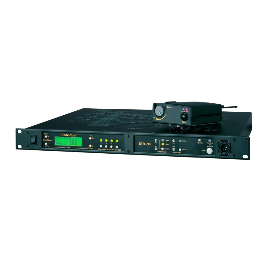
Telex RadioCom BTR-700 Operating Instructions Manual
Professional wireless intercom system
Hide thumbs
Also See for RadioCom BTR-700:
- Supplementary manual (1 page) ,
- Operating instructions manual (65 pages) ,
- Operating instructions manual (63 pages)

Related Manuals for Telex RadioCom BTR-700


Summary of Contents for Telex RadioCom BTR-700
- Page 1 Telex Op er ating In struc tions RadioCom ™ BTR-700, TR-700 Pro fes sional Wire less In ter com Sys tem...
- Page 3 Thank you for choos ing RadioCom™ Telex Com mu ni ca tions would like to take this op por tu nity to thank you for choos ing the RadioCom™ BTR-700 Pro fes sional Wire less In ter com Sys tem. Many of the fea tures in this prod uct are the re sult of years of de vel op - - ment work with many of the fea tures de vel oped from cus tomer feed back.
-
Page 5: Table Of Contents
BTR-700 Menu Struc ture........ - Page 6 Beltpack Op er a tion ............... . 6-11 Power/Lo cal Head set Vol ume.
-
Page 7: In Tro Duc Tion
AA al ka line bat ter ies. RTS® and Audiocom® are reg is tered trade marks of Telex Com mu ni ca tions, Inc. Clear-Com® is a reg is tered trade mark of Clear-Com In ter com Sys tems, Inc. -
Page 9: Btr-700 Base Sta Tion
12. Lo cal Head set Con nec tor – Male XLR con nec tor for Telex units, Fe male XLR con nec tor for RTS units. A dy - namic or electret head set mi cro phone is au to mat i cally de - tected. -
Page 10: Con Trols And Con Nec Tions - Rear Panel
3. Trans mit ON/OFF Switch – Turns the trans mit ter on or off. 4. I/C Se lect Switch – Set to the ap pro pri ate 2-wire in ter com type be ing in ter faced to the unit. Set to ei ther Telex, RTS or Clear-Com®. -
Page 11: Btr-700 Specifications
Telex In ter com....In put/Out put Level Ad just able (1 Vrms typ i cal), Line im ped ance 300... - Page 12 2-4 Blank...
-
Page 13: Tr-700 Beltpack
If the gain is too large, the LED will be red dur ing the com plete word at nor mal speech lev els. Telex BAT/OM TALK TALK... -
Page 14: Con Trols And Con Nec Tions - Rear Panel
6. Head set Con nec tor – Male XLR con nec tor for Telex units, Fe male XLR con nec tor for RTS units. A dy namic or electret head set mi cro phone is au to mat i cally de tected by the beltpack and a bias volt age sup plied if needed. -
Page 15: Tr-700 Spec I Fi Ca Tions
TR-700 Spec i fi ca tions RF Fre quency Range..518 - 608 MHz, 614 - 740 MHz, 796 - 868 MHz in 18 MHz TX and RX bands Power Re quire ments........6 “AA” Cells Al ka line (NiMH op tional) Cur rent Draw . - Page 16 3-4 Blank...
-
Page 17: Ini Tial Equip Ment Set-Up
Con tact the ship per or your dealer im me di ately if any thing is dam aged or miss ing. Fill out the reg is tra tion card and re turn it to Telex to reg is ter the unit. De scrip tion... -
Page 18: An Tenna Con Nec Tions
Attaching Receive 1/2-Wave An tenna An tenna Po lar iza tion The Telex Wire less In ter com Sys tem is “Ver ti cally Po lar ized”. This means both the trans mit ting and re ceiv ing an ten nas should op er ate in the ver ti cal po si tion. - Page 19 - - mance. 700 FEET 100 FEET RadioCom MENU ä 2 WIRE BTR-700 ClearScan 4 WIRE SELECT COPY DOWN PORTABLE STATION CONNECT INTERCOM AUXILIARY...
-
Page 20: Im Proving Re Cep Tion/In Creasing Range
- mote an ten nas is OK. elex MENU RadioCom ä 2 WIRE ON/O.M. VOLUME TALK/O.M. ClearScan BTR-700 4 WIRE MIC GAIN SELECT ON/OFF TALK DOWN COPY PORTABLE STATION CONNECT INTERCOM AUXILIARY RadioCom MENU ä... -
Page 21: Base Sta Tion Set-Up
Base Sta tion Set-up BTR-700 RECEIVE FCC ID: B5DM516 CANADA 1321231218A TRANSMIT POWER TELEX COMMUNICATIONS INC. HIGH NORM MADE IN USA TELEX CLEARCOM TRANSMIT SWITCHES INTERCOM SWITCH Lo ca tion Lo cate the base sta tion with the front and rear of the unit ac - - ces si ble so that switches may be set and con nec tions made. -
Page 22: In Ter Com Switch
In ter com In ter face Telex (Audiocom®) and Clear-Com® in ter com sys tems re - - quire one ca ble for in ter com. This in ter fac ing is done through the I/C 3 pin XLR con nec tors on the rear of the unit. -
Page 23: Aux Il Iary In Put/Out Put
FCC ID: B5DM516 CANADA 1321231218A TRANSMIT POWER HIGH NORM TELEX COMMUNICATIONS INC. MADE IN USA TELEX CLEARCOM Aux il iary In put/Out put The in put and out put 3-pin aux il iary con nec tions are for sup - - ply ing ad di tional bal anced au dio into and re ceiv ing bal anced au dio from the base sta tion. -
Page 24: Beltpack Set-Up
Beltpack Set-up Bat tery In stal la tion En sure that the On/Off vol ume con trol knob is turned off. Press down and hold down the bat tery re lease latch, slide the bat tery pack about 1/8 inch back, to ward the latch, un til it stops. -
Page 25: An Tenna Con Nec Tion
“TR-700 beltpack con trols and con nec tions” sec tion if this is not a Telex head set. A dy namic or electret head set mi cro phone is au to mat i cally de tected by the beltpack and a bias volt age sup plied if needed. - Page 26 4-10 Blank...
-
Page 27: Pre-Walk-Thru Check List
Fol low ing the in struc tions fully to this point you have suc cess - - fully com pleted the fol low ing check list: Lo cated the base sta tion prop erly. Con nected power to base sta tion. Con nected the 1/2-wave an ten nas to the base sta tion. - Page 28 5-2 Blank...
-
Page 29: System Op Er A Tion
- - ceive chan nels from which to choose. Each chan nel rep re sents a unique fre quency. For ex am ple, one BTR-700 could be set on Group 02A and chan nels 01, 02, 03 and 04. The other BTR-700 could be set on Group 02B chan nels 05, 06, 07 and 08. -
Page 30: Base Sta Tion Op Er A Tion
LED will in di cate the cur rent mode of the in ter com chan nel. If the base sta tion is con nected to a 2-wire sys - - tem, such as Audiocom (Telex), RTS TW or Clear-Com®, set the in ter com to 2-wire. If it is con nected to a four-wire sys tem, such as RTS Ma trix, set the in ter com to 4-wire. -
Page 31: Dis Play Con Trast
The con trast con trol is in ter - - nal to the BTR-700 unit near the front panel. The cover must be re moved for ac cess to this con trol. Please see Fig ure 20 for the lo ca tion. -
Page 32: Btr-700 Menu Structure
BTR-700 Menu Structure Main Screen Flowchart The fol low ing con tains the base station menu struc ture and ref er ences the pages in which fur ther de tail of that menu may be found. Power-Up Screen - Pg. 6-5... -
Page 33: Beltpack Ac Tiv Ity Code Def I Ni Tions
Beltpack Ac tiv ity Code Def i ni tions: no tx = No Beltpack Trans mit Car rier De tected = Re ceiver is not se lected on front panel = Beltpack is on Power-Up Screen Telex RadioCom Operating Screen Group 03A B20001... -
Page 34: Group/Chan Nel Se Lect
Group / Chan nel Se lect The Group/Chan nel se lect screen al lows the user to change the group and se lect from a pre-determined num ber of chan nels on each re ceiver. • Hit [MENU] once to en ter the Group / Chan nel Se lect Screen from the op er at ing screen. -
Page 35: Group/Fre Quency Se Lect
Group / Fre quency Se lect The Group/Fre quency se lect screen al lows a user to set the group and se lect from a pre-determined num ber of fre quen cies on each re ceiver. Each fre quency dis played on the right half of the screen corresponds to a chan nel num ber in the Group/Chan nel Screen. -
Page 36: Fre Quency Edit
Fre quency Edit (User-Programmed Groups Only) This menu only oc curs for user-programmable groups or when copy ing to a user-programable group. The Fre quency Edit screen al lows the user to set the group trans mit fre quen cy and re ceive chan nel fre quen cies of a user-programmable group. -
Page 37: Clearscan
ClearScan ClearScan per forms a fre quency scan of the fac tory -de fined and any set-up user-programmable groups in or der to find the group with the high est num ber of clear re ceive chan nels. Af ter about 20-30 sec onds, the group with the high est num ber of clear re ceive chan nels will be dis played. -
Page 38: Spe Cial Key Se Quences
Spe cial Key Se quences Lock out • Press [UP]+[DOWN] for 3 sec onds to lock or un lock the base sta tion. Pressing [MENU] will still func tion to view screens, but [SET] will no lon ger start any ed it ing. ClearScan™, First use, Fac tory de fault are no lon ger ac - ces si ble. -
Page 39: Beltpack Op Er A Tion
Beltpack Op er a tion POWER LOCAL HEADSET VOLUME Telex Power / Lo cal Head set Vol ume Turn the beltpack power on by ro tat ing the knob CW. Ad just the vol ume to the head set by ro tat ing the vol ume con trol as re - - quired for a com fort able lis ten ing vol ume. -
Page 40: Beltpack Menu Struc Ture
TR-700 Menu Struc ture Beltpack Menu Struc ture The fol low ing con tains the main beltpack menu struc ture and ref er - - ences the pages in which fur ther de tail of that menu may be found. All beltpack fea tures and spe cial key se quences can only be done from the group/channel screen. -
Page 41: Power-Up Screens
Power-Up Screens • The first screens dis played when the beltpack is pow ered up are the soft ware and chan nel map ver sion screens. • The 1 screen dis played in di cates the beltpack’s soft ware ver sion num ber. It is dis played for about one sec ond. •... -
Page 42: Group/Chan Nel Screen
Group / Chan nel Screen The Group/Chan nel screen al lows the user to change the group and se lect from a pre-determined num ber of trans mit chan nels. • The screen dis played af ter the beltpack pow er-up screens. •... -
Page 43: Trans Mit Screen
Trans mit Screen The Transmit screen al lows the user to set the beltpack trans - - mit fre quency. Fac tory-defined groups will al low only a set num ber of pre-defined fre quen cies to be se lected. User-programmable groups will al low the user to change the fre quency in 25kHz steps. -
Page 44: Re Ceive Screen
Re ceive Screen The Receive screen al lows the user to set the beltpack re ceive fre quency. This cor re sponds to the base sta tion’s trans mit fre - - quency. In fac tory-defined groups re ceive is not change able. User-programable groups will al low the user to change the fre quency in 25 KHz steps. -
Page 45: Clearscan
ClearScan™ ClearScan™ per forms a fre quency scan of the fac tory-defined and any set-up user-programmable groups in or der to find the clear est group. Af ter about 30 sec onds, the clear est group is dis played. A group is de fined by the re ceive fre quen cy. The next best group and so forth may be ac cessed with the [DOWN] and [UP] ar row but tons. -
Page 46: Talk But Ton Latch On/Latch Off
Talk But ton Latch on/Latch off • Press and hold [SET] then press the [TALK] but ton to show the Talk But ton Latch/Non-Latching screen. The cur rent set ting of the fea ture is dis played on the LCD dis - play. -
Page 47: Sys Tem Walk-Thru
In 99% of all in stances you will set up your Telex Wire less In - - ter com Sys tem, walk it through the area of in ter est and achieve error-free per for mance. - Page 48 7-2 Blank...
-
Page 49: Trou Ble Shooting
Make sure that all the Telex beltpack(s) are on. If there are any unused receivers at the base, turn the audio off from those receivers by deselecting the appropriate “Portable Station Connect”... - Page 50 8-2 Blank...
-
Page 51: Tech Tips
RF de vices. The fac tory de fined fre quen cies (Groups 01A-24) se - - lected by Telex for this RadioCom™ sys tem are cho sen to min i mize pos si ble in ter fer ence. - Page 52 9-2 Blank...
-
Page 53: Bat Tery Information
Im proper bat tery se lec tion, use, in stal la tion and care are the cause of nu mer ous wire less sys tem fail ures. Al ka line Bat teries: Al ka line bat ter ies such as Mallory’s DURACELL®... - Page 54 10-2 Blank...
- Page 55 Send: ...20kHz 100 Hz, 240 mVrms Re ceive: ...20kHz 800 Hz, 100 mVrms Power Volt age: ...28.0 VDC nom i nal AudioCom/Telex In put Im ped ance: ...300 Out put Level:...1.0 Vrms nom i nal Bridging Im ped ance: ...>10k Call Sig naling: Send: ...20kHz 100 Hz, 05 mVrms...
- Page 56 11-2 Blank...
-
Page 57: Ac Ces Sories And Re Place Ment Parts
U.K..550024002 Eu ro pean ...550024000 Aus tra lian ...550024018 BTR In ter com Dummy Load Or der No. 71147000 Telex type...PN 878935 RTS type ...PN 878990 TR LCD/ switch cover Order No. 690419 BP-700 TR Bat tery pack, al ka line 71151-025 (bat ter ies not in cluded)...PN 71315-000... - Page 58 12-2 Blank...
-
Page 59: Cus Tomer Ser Vice In For Ma Tion
Telex re serves the right to make changes in de sign and im prove ment on its prod uct with out as sum ing any ob li ga tion to in stall the same on any of its prod ucts pre vi ously man u fac tured. Fur ther Telex re serves the right to ship new and/or im proved prod ucts which are sim i lar to the form, fit and func tion of prod - ucts orig i nally or dered. - Page 60 13-2 Blank...
-
Page 61: Soft Ware Li Cense
IM POR TANT - Please red this doc u ment care fully be fore us ing this prod uct. THIS DOC U MENT STATES THE TERMS AND CON DI TIONS UPON WHICH TELEX COM MU NI CA TIONS, INC. (the “COM PANY”) OF FERS TO LI CENSE THE IN STALLED SOFT WARE OR PRO GRAM (the “SOFT - WARE”) FOR USE WITH THE PRO DUCT IN WHICH IT WAS IN STALLED. - Page 62 14-2 Blank...
-
Page 63: Certification In For Ma Tion
The Telex BTR-700 and the TR-700 Trans mit ter/Re ceiver are Type Ac cepted un der United States Fed eral Com mu ni ca tions Com mis sion Part 74. Li censing of Telex equip ment is the User’s re spon si bil ity and licensibility de pends on the user’s clas si fi ca tion, us ers ap pli ca tion, and fre quency se lected. - Page 64 15-2 Blank...
-
Page 65: Limited War Ranty
1. De liv ery of the prod uct or parts post age pre paid to the Telex dealer, au tho rized ser vice fa cil ity or fac tory. 2. De ter mi na tion by Telex that a de fect ex ists and is cov ered by lim ited war ranty. De fects due to al ter ation, re pair by un -... - Page 66 16-2 Blank...
- Page 68 • TELEX COM MU NI CA TIONS, INC. 12000 Port land Ave. South, Burnsville, MN 55337. PN 803290-2 REV C MAY 2003 Made in U.S.A.
Need help?
Do you have a question about the RadioCom BTR-700 and is the answer not in the manual?
Questions and answers