Table of Contents
Advertisement
Quick Links
Copyright
This publication, including all photographs, illustrations and software, is protected
under international copyright laws, with all rights reserved. Neither this manual, nor
any of the material contained herein, may be reproduced without written consent of
the author.
Version 2.0
Disclaimer
The information in this document is subject to change without notice. The manufac-
turer makes no representations or warranties with respect to the contents hereof and
specifically disclaims any implied warranties of merchantability or fitness for any
particular purpose. The manufacturer reserves the right to revise this publication and
to make changes from time to time in the content hereof without obligation of the
manufacturer to notify any person of such revision or changes.
Trademark Recognition
Microsoft, MS-DOS and Windows are registered trademarks of Microsoft Corp.
AMD, Phenom, Athlon, Sempron and Duron are registered trademarks of AMD
Corporation.
Other product names used in this manual are the properties of their respective owners
and are acknowledged.
Federal Communications Commission (FCC)
This equipment has been tested and found to comply with the limits for a Class B
digital device, pursuant to Part 15 of the FCC Rules. These limits are designed to
provide reasonable protection against harmful interference in a residential installa-
tion. This equipment generates, uses, and can radiate radio frequency energy and, if
not installed and used in accordance with the instructions, may cause harmful inter-
ference to radio communications. However, there is no guarantee that interference
will not occur in a particular installation. If this equipment does cause harmful
interference to radio or television reception, which can be determined by turning the
equipment off and on, the user is encouraged to try to correct the interference by one
or more of the following measures:
•
Reorient or relocate the receiving antenna
•
Increase the separation between the equipment and the receiver
•
Connect the equipment onto an outlet on a circuit different from that to
which the receiver is connected
•
Consult the dealer or an experienced radio/TV technician for help
Shielded interconnect cables and a shielded AC power cable must be employed with
this equipment to ensure compliance with the pertinent RF emission limits governing
this device. Changes or modifications not expressly approved by the system's manu-
facturer could void the user's authority to operate the equipment.
Preface
Preface
Advertisement
Table of Contents

Related Manuals for ECS GF8200SM-M3


Summary of Contents for ECS GF8200SM-M3
- Page 1 Preface Copyright This publication, including all photographs, illustrations and software, is protected under international copyright laws, with all rights reserved. Neither this manual, nor any of the material contained herein, may be reproduced without written consent of the author. Version 2.0 Disclaimer The information in this document is subject to change without notice.
-
Page 2: Declaration Of Conformity
Declaration of Conformity This device complies with part 15 of the FCC rules. Operation is subject to the following conditions: • This device may not cause harmful interference, and • This device must accept any interference received, including interfer- ence that may cause undesired operation Canadian Department of Communications This class B digital apparatus meets all requirements of the Canadian Interference- causing Equipment Regulations. -
Page 3: Table Of Contents
T T T T T ABLE OF CONTENTS ABLE OF CONTENTS ABLE OF CONTENTS ABLE OF CONTENTS ABLE OF CONTENTS Preface Chapter 1 Introducing the Motherboard Introduction..................1 Feature ....................2 Motherboard Components.............5 7 7 7 7 7 Chapter 2 Installing the Motherboard Safety Precautions................7 Choosing a Computer Case............7 Installing the Motherboard in a Case..........7... - Page 4 PCI/PNP Configuration.............38 PC Health Status..............39 Frequency/Voltage Control..........41 Load Default Settings............42 Supervisor Password............42 User Password..............43 Save & Exit Setup..............43 Exit Without Saving............43 Updating the BIOS.............44 Chapter 4 45 45 45 45 Using the Motherboard Software About the Software DVD-ROM/CD-ROM.........45 Auto-installing under Windows XP/Vista/7.......45 Running Setup..............46 Manual Installation................48 Utility Software Reference............48...
-
Page 5: Introducing The Motherboard
Chapter 1 Introducing the Motherboard Introduction Thank you for choosing the GF8200SM-M3 motherboard. This motherboard is a high performance, enhanced function motherboard that supports socket for Phenom processor (socket AM2+)/AMD Athlon 64 X2 Dual-Core/Athlon Sempron processors for high-end business or personal desktop markets. -
Page 6: Feature
Feature Processor This motherboard uses a socket AM2+/AM2 that carries the following features: • Accommodates AMD Phenom processor (socket AM2+) AMD Athlon 64 X2 Dual-Core/Athlon 64/Sempron processors • Supports HyperTransport (HT) 3.0 interface speeds HyperTransport Technology is a point-to-point link between two devices, it enables integrated circuits to exchange information at much higher speeds than currently available interconnect technologies. - Page 7 Audio (Optional) The onboard Audio provides either of the following features: • 5.1 Channel High Definition Audio Codec • DACs Support 96K/48K/44.1KHz DAC sample rate • Power support: Digital:3.3V; Analog:5.0V • and Tru Surround from SRS • Provides single ended CD input with DRM solutions and legacy OS issues •...
-
Page 8: Bios Firmware
BIOS Firmware The motherboard uses AMI BIOS that enables users to configure many system features including the following: • Power management • Wake-up alarms • CPU parameters • CPU and memory timing The firmware can also be used to set parameters for different processor clock speeds. -
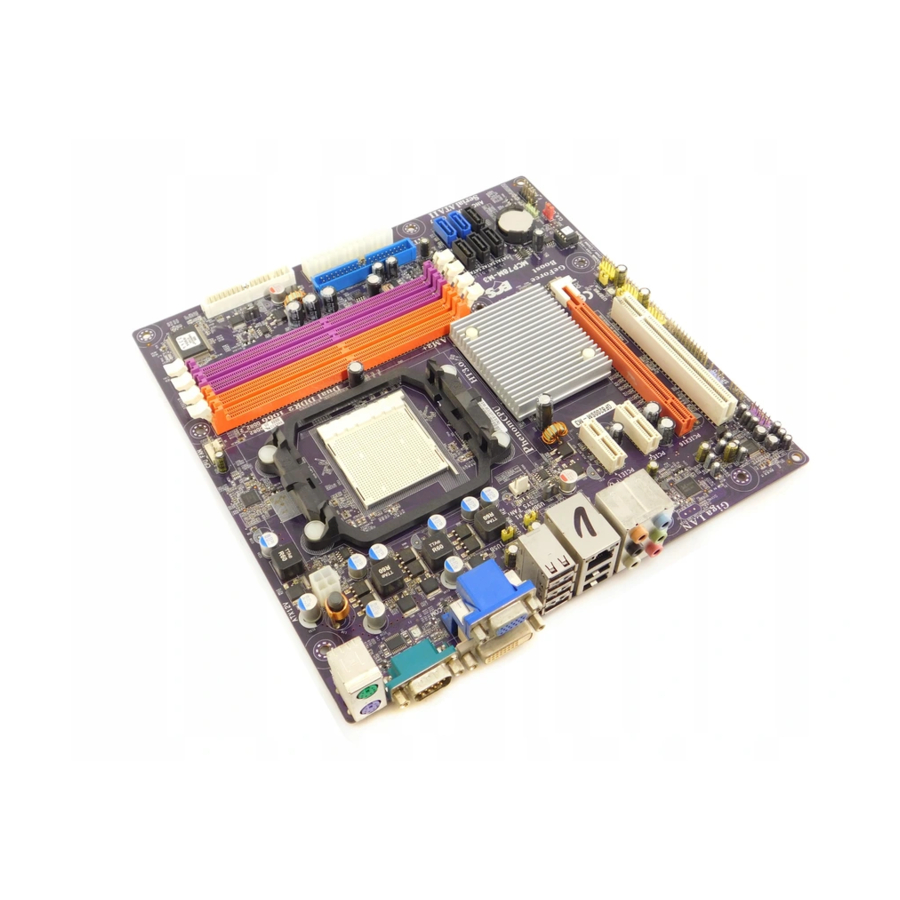
Page 9: Motherboard Components
Motherboard Components Introducing the Motherboard... - Page 10 Table of Motherboard Components LABEL C O MPO NENTS Socket for AMD Phenom processor (socket AM2+)/AMD 1. CPU Socket Athlon 64 X2 Dual-Core/Athlon 64/Sempron processors 2. CPU_FAN CPU cooling fan connector 3. DDR2_1~4 240-pin DDR2 SDRAM slots 4. FDD Floppy disk drive connector 5.
-
Page 11: Installing The Motherboard
Chapter 2 Installing the Motherboard Safety Precautions • Follow these safety precautions when installing the motherboard • Wear a grounding strap attached to a grounded device to avoid dam- age from static electricity • Discharge static electricity by touching the metal case of a safely grounded object before working on the motherboard •... -
Page 12: Checking Jumper Settings
Do not over-tighten the screws as this can stress the motherboard. Checking Jumper Settings This section explains how to set jumpers for correct configuration of the motherboard. Setting Jumpers Use the motherboard jumpers to set system configuration options. Jumpers with more than one pin are numbered. -
Page 13: Checking Jumper Settings
Checking Jumper Settings The following illustration shows the location of the motherboard jumpers. Pin 1 is labeled. Jumper Settings Jumper Type Description Setting (default) 1-2: NORMAL 2-3: CLEAR CLR_CMOS 3-pin CLEAR CMOS Before clearing the CMOS, make sure to CLR_CMOS turn the system off. -
Page 14: Installing Hardware
Installing Hardware Installing the Processor Caution: When installing a CPU heatsink and cooling fan make sure that you DO NOT scratch the motherboard or any of the surface-mount resis- tors with the clip of the cooling fan. If the clip of the cooling fan scrapes across the motherboard, you may cause serious damage to the motherboard or its components. -
Page 15: Installing Memory Modules
CPU Installation Procedure The following illustration shows CPU installation components. Unhook the locking lever of the CPU socket. Pull the locking lever away from the socket and raising it to the upright position. Match the pin1 corner marked as the beveled edge on the CPU with the pin1 corner on the socket. -
Page 16: Installation Procedure
Do not remove any memory module from its antistatic packaging until you are ready to install it on the motherboard. Handle the modules only by their edges. Do not touch the components or metal parts. Always wear a grounding strap when you handle the modules. Installation Procedure Refer to the following to install the memory modules. - Page 17 Table A: DDR2 (memory module) QVL (Qualified Vendor List) The following DDR2 1066 (AM2+)/800/667/533/400 memory modules have been tested and qualified for use with this motherboard. Type Size Vendor Module Name M378T3354BZ0-CCC Samsung 256 MB K4T51163QB-ZCCC M378T6553BG0-CCC DDR2 400 Samsung K4T51083QB-GCCC 512 MB Tw inMos...
- Page 18 Type Siz e Ve ndor Module Name Ramaxel 256 MB 5NB31 D9DCG A-DATA AD29608A88-3EG Corsair VALUESELECT 32M8CEC GEIL GL2L64M088BA18W Ramxel 5LB31 D9DCL K4T51083QC 512 MB Samsung PC35300U-25331-Z DDR2 667 K4T56083QF-ZCE6 Sync MAX 04400WB01 R050008A Transcend JetRam J12Q3AB-6 Tw inmos TMM6208G8M30B Kingston KVR667D2N5/1G Samsung...
-
Page 19: Expansion Slots
Expansion Slots Installing Add-on Cards The slots on this motherboard are designed to hold expansion cards and connect them to the system bus. Expansion slots are a means of adding or enhancing the motherboard’s features and capabilities. With these efficient facilities, you can increase the motherboard’s capabilities by adding hardware that performs tasks that are not part of the basic system. - Page 20 Follow these instructions to install an add-on card: Remove a blanking plate from the system case corresponding to the slot you are going to use. Install the edge connector of the add-on card into the expansion slot. Ensure that the edge connector is correctly seated in the slot. Secure the metal bracket of the card to the system case with a screw.
-
Page 21: Connecting Optional Devices
Connecting Optional Devices Refer to the following for information on connecting the motherboard’s optional devices: F_AUDIO: Front Panel Audio header This header allows the user to install auxiliary front-oriented microphone and line- out ports for easier access. Signal Name Signal Name Signal Name Function PORT 1L... - Page 22 F_USB1~3: Front Panel USB headers The motherboard has six USB ports installed on the rear edge I/O port array. Addi- tionally, some computer cases have USB ports at the front of the case. If you have this kind of case, use auxiliary USB connector to connect the front-mounted ports to the motherboard.
- Page 23 LPT: LPT header Signal Name Signal Name Function Signal Name Function STB# Strobe Data 0 Data 1 Data 2 Data 3 Data 4 Data 5 Data 6 Data 7 ACK# Acknowledge BUSY Busy Paper End SLCT Select AFD# Auto Feed ERR# Error INIT#...
-
Page 24: Installing A Hard Disk Drive/Cd-Rom/Sata Hard Drive
Installing a Hard Disk Drive/CD-ROM/SATA Hard Drive This section describes how to install IDE devices such as a hard disk drive and a CD- ROM drive. About IDE Devices Your motherboard has one IDE interface. IDE: IDE Connector This motherboard supports five high data transfer SATA ports with each runs up to 3.0 Gb/s. -
Page 25: Installing A Floppy Diskette Drive
Refer to the illustration below for proper installation: Attach either cable end to the connector on the motherboard. Attach the other cable end to the SATA hard drive. Attach the SATA power cable to the SATA hard drive and connect the other end to the power supply. -
Page 26: Connecting I/O Devices
Connecting I/O Devices The backplane of the motherboard has the following I/O ports: PS2 Mouse Use the upper PS/2 port to connect a PS/2 pointing device. PS2 Keyboard Use the lower PS/2 port to connect a PS/2 keyboard. Serial Port Use the COM port to connect serial devices such as mouse (COM) or fax/modems. -
Page 27: Connecting Case Components
Connecting Case Components After you have installed the motherboard into a case, you can begin connecting the motherboard components. Refer to the following: Connect the CPU cooling fan cable to CPU_FAN. Connect the system cooling fan connector to SYS_FAN. Connect the standard power supply connector to ATX_POWER. Connect the auxiliary case power supply connector to ATX12V. -
Page 28: Atx 12V Power Connector
CPU_FAN: CPU cooling FAN Power Connector Signal Name Function System Ground Power +12V +12V Sense Sensor Control CPU FAN control Users please note that the fan connector supports the CPU cooling fan of 1.1A ~ 2.2A (26.4W max) at +12V. SYS_FAN: FAN Power Connectors Signal Name Function... -
Page 29: Front Panel Header
Front Panel Header The front panel header (F_PANEL) provides a standard set of switch and LED headers commonly found on ATX or Micro ATX cases. Refer to the table below for informa- tion: Signal Function Signal Function HD_LED_P Hard disk LED (+) 2 FP PWR/SLP *MSG LED (+) HD_LED_N Hard disk LED (-) FP PWR/SLP *MSG LED (-) - Page 30 Memo Installing the Motherboard...
-
Page 31: Using Bios
Chapter 3 Using BIOS About the Setup Utility The computer uses the latest “American Megatrends Inc. ” BIOS with support for Windows Plug and Play. The CMOS chip on the motherboard contains the ROM setup instructions for configuring the motherboard BIOS. The BIOS (Basic Input and Output System) Setup Utility displays the system’s configuration status and provides you with options to set system parameters. -
Page 32: Resetting The Default Cmos Values
Press the delete key to access the BIOS Setup Utility. CMOS Setup Utility -- Copyright (C) 1985-2007, American Megatrends, Inc. Standard CMOS Setup Frequency/Voltage Control Advanced Setup Load Default Settings Advanced Chipset Setup Supervisor Password Integrated Peripherals User Password Power Management Setup Save &... -
Page 33: Using Bios
Using BIOS When you start the Setup Utility, the main menu appears. The main menu of the Setup Utility displays a list of the options that are available. A highlight indicates which option is currently selected. Use the cursor arrow keys to move the highlight to other options. -
Page 34: Standard Cmos Setup
For the purpose of better product maintenance, the manufacture reserves the right to change the BIOS items presented in this manual. The BIOS setup screens shown in this chapter are for reference only and may differ from the actual BIOS. Please visit the manufacture’s website for updated manual. - Page 35 Type (Auto) Use this item to configure the type of the IDE device that you specify. If the feature is enabled, it will enhance hard disk performance by reading or writing more data during each transfer. LBA/Large Mode (Auto) Use this item to set the LAB/Large mode to enhance hard disk performance by optimizing the area the hard disk is visited each time.
-
Page 36: Advanced Setup
Advanced Setup This page sets up more advanced information about your system. Handle this page with caution. Any changes can affect the operation of your computer. CMOS Setup Utility - Copyright (C) 1985-2007, American Megatrends, Inc. Advanced Setup Help Item HT Frequency Auto Auto AMD C&Q... -
Page 37: Advanced Setup
Removable Drives (Press Enter) Scroll to this item and press <Enter> to view the following screen: CMOS Setup Utility - Copyright (C) 1985-2007, American Megatrends, Inc. Removable Drives Help Item Removable Drives 1st Drive 1st FLOPPY DRIVE Specifies the boot sequence from the available devices. - Page 38 Share Memory Auto Detection (Auto) Disable this item to set the Share Memory Size. And if the item is set to Auto, Share Memory Size can be controlled according to the dram size. When the dram size is less than 512 MB, Share Memory Size should be set to 64 MB. While between 512 MB and 1 GB, it should be set to 128 MB.
-
Page 39: Integrated Peripherals
Integrated Peripherals This page sets up some parameters for peripheral devices connected to the system. CMOS Setup Utility - Copyright (C) 1985-2007, American Megatrends, Inc. Integrated Peripherals Onboard IDE Controller Enabled Help Item OnChip S-ATA Controller Enabled SATA Mode select SATA Mode Onboard AUDIO Function Enabled... -
Page 40: Power Management Setup
Parallel Port IRQ (IRQ7) Use this item to assign IRQ to the parallel port. USB Controller (Enabled) Use this item to enable or disable the USB function. Legacy USB Support (Enabled) Use this item to enable or disable support for legacy USB devices. Press <Esc>... - Page 41 Resume By RING (Disabled) The system can be turned off with a software command. If you enable this item, the system can automatically resume if there is an incoming call on the Modem. You must use an ATX power supply in order to use this feature. Resume By PCI/PCI-E/Lan PME (Disabled) The system can be turned off with a software command.
-
Page 42: Pci/Pnp Configuration
PCI / PnP Setup This page sets up some parameters for devices installed on the PCI bus and those utilizing the system plug and play capability. CMOS Setup Utility - Copyright (C) 1985-2007, American Megatrends, Inc. PCI / PnP Setup Help Item iGPU and Ext-VGA Selection Single... -
Page 43: Pc Health Status
PC Health Status On motherboards support hardware monitoring, this item lets you monitor the parameters for critical voltages, temperatures and fan speeds. CMOS Setup Utility - Copyright (C) 1985-2007, American Megatrends, Inc. PC Health Status Help Item Hardware Health Event Monitoring Smart Fan Function Press Enter ShutDown Temperature... - Page 44 ShutDown Temperature (Disabled) Enable you to set the maximum temperature the system can reach before powering down. System Component Characteristics These items display the monitoring of the overall inboard hardware health events, such as System & CPU temperature, CPU & DIMM voltage, CPU & system fan speed,...etc.
-
Page 45: Frequency/Voltage Control
Frequency/Voltage Control This page enables you to set the clock speed and system bus for your system. The clock speed and system bus are determined by the kind of processor you have in- stalled in your system. CMOS Setup Utility - Copyright (C) 1985-2007, American Megatrends, Inc. Frequency/Voltage Control Help item Auto Detect DIMM/PCI CIK... -
Page 46: Load Default Settings
Load Default Settings This option opens a dialog box to ask if you are sure to install optimized defaults or not. You select [OK], and then <Enter>, the Setup Utility loads all default values; or select [Cancel], and then <Enter>, the Setup Utility does not load default values. Supervisor Password This page helps you install or change a password. -
Page 47: User Password
User Password This page helps you install or change a password. CMOS Setup Utility - Copyright (C) 1985-2007, American Megatrends, Inc. User Password User Password : Not Installed Help item Change User Password Press Enter Install or Change the password. <... -
Page 48: Updating The Bios
Updating the BIOS You can download and install updated BIOS for this motherboard from the manufacturer’s Web site. New BIOS provides support for new peripherals, improve- ments in performance, or fixes for known bugs. Install new BIOS as follows: If your motherboard has a BIOS protection jumper, change the setting to allow BIOS flashing. -
Page 49: Using The Motherboard Software
Chapter 4 Using the Motherboard Software About the Software DVD-ROM/CD-ROM The support software DVD-ROM/CD-ROM that is included in the motherboard package contains all the drivers and utility programs needed to properly run the bundled products. Below you can find a brief description of each software program, and the location for your motherboard version. -
Page 50: Running Setup
Drivers Tab Setup Click the Setup button to run the software installation program. Select from the menu which software you want to install. Browse CD The Browse CD button is the standard Windows command that allows you to open Windows Explorer and show the contents of the support disk. - Page 51 Click Next. The following screen appears: Check the box next to the items you want to install. The default options are recom mended. Click Next run the Installation Wizard. An item installation screen appears: Follow the instructions on the screen to install the items. Drivers and software are automatically installed in sequence.
-
Page 52: Manual Installation
These software(s) are subject to change at anytime without prior notice. Please refer to the support disk for available software. Please go to ECS website to download AMD Cool’n’Quiet technology. This concludes chapter 4. Using the Motherboard Software... -
Page 53: Setting Up Nvidia Raid Configuration
Chapter 5 Setting Up NVIDIA RAID Configuration There are two ways to setup NVIDIA RAID Configuration: one is to create a RAID 1 Array for backup or a RAID 0 Array for increased performance just by adding additional disk array without changing the original OS (Non-Bootable RAID Array); while the other is to configure the RAID Array disks when reinstalling the OS (Bootable RAID Array). - Page 54 From the Integrated Peripherals Window, globally set SATA Mode select to RAID Mode (see Figure 1.2). Press F10 to save the configuration and exit (F10 is the navigation key to save the current configuration and exit setup in BIOS setting). The PC reboots.
-
Page 55: Setting Up A Bootable Raid Array
Setting Up a Bootable RAID Array This section explains how to configure a bootable NVIDIA RAID array. Setting Up the BIOS Start your computer, then press Delete to enter the BIOS setup. The BIOS CMOS Setup Utility screen appears. Figure 1.4 BIOS CMOS Setup Utility Main Screen Use the arrow keys to select Integrated Peripherals (see Figure 1.4), then press Enter. - Page 56 Press F10 to save the configuration and exit. The PC reboots. Enter the RAID BIOS Setup by pressing F10 when prompted, and proceed to set up the NVIDIA RAID BIOS as described in the next section. Configuring the NVIDIA RAID BIOS The NVIDIA RAID BIOS set up lets you choose the RAID type and which hard drives you want to make part of the array.
- Page 57 The NVIDIA RAID Utility—Define a New Array screen appears (Figure 1.7). Figure 1.7 MediaShield BIOS By default, RAID Mode is set to Mirroring and Striping Block is set to Optimal. Using the Define a New Array Screen If necessary, press the tab key to move from field to field until the appropriate field is highlighted.
- Page 58 Figure 1.8 illustrates the Define a New Array screen after one disk have been assigned as RAID 0 array disk. Figure 1.8 MediaShield BIOS—Array Disks Assigned Completing the RAID BIOS Setup After assigning your RAID array disk, press F7. The Clear disk array prompt appears. Figure 1.9 Clear Disk Data Prompt NVIDIA RAID Configuration...
- Page 59 Press Y to clear the disk data. The Array List screen appears, where you can review the RAID arrays that you have set up. Figure 1.10 Array List Window Use the arrow keys to select the array that you want to set up, then press B to specify the array as bootable.
- Page 60 Installing the RAID Drivers Your system may come with a Windows install CD that already includes NVIDIA RAID drivers. If so, then this section is not relevant. If that is not the case (or you are trying to install a new version of Windows), then you will need an NVIDIA RAID driver F6 install floppy.
- Page 61 Select “NVIDIA RAID CLASS DRIVER (required)” and then press Enter. Press S again at the Specify Devices screen, then press Enter. Select “NVIDIA NForce Storage Controller (required)” and then press Enter. The following Windows Setup screen appears listing both drivers:. Figure 1.13 Windows Setup—NVIDIA drives listed Press Enter to continue with Windows XP Installation.
- Page 62 Memo NVIDIA RAID Configuration...
-
Page 63: Nvidia Hybrid Sli Technology Support
Chapter 6 NVIDIA Hybrid SLI Technology Support ® ® ® ® ® ® ® ® ® ® This motherboard supports the NVIDIA® Hybrid SLI® Technology. Hybrid SLI® technology, based on NVIDIA’s industry-leading SLI technology, deliv- ers multi-GPU (graphics processing unit) benefits when an NVIDIA® motherboard GPU is combined with an NVIDIA discrete GPU. -
Page 64: Hybrid Sli Products
Hybrid SLI products Hybrid SLI Enabled Motherboard GPUs Hybrid Power GeForce Boost Technology Technology GeForce 8300 GeForce 8200 GeForce 8100 nForce 730a nForce 720a For reference only Hybrid SLI Enabled Graphics Card GPUs Hybrid SLI Technology Hybrid Power GeForce Boost GeForce 9800 GX2 GeForce 9800 GTX GeForce 8500 GT... -
Page 65: Hybrid Requirements And Constraints
2 × 1024 MB of DDR2-800 DRAM • Discrete GPU recommended for GeForce Boost Visit the ECS website (www.ecs.com.tw) for for more information of this motherboard. Make sure that your graphics card driver supports the NVIDIA® Hybrid SLI® Technology. Download the latest driver from the NVIDIA website (www.nvidia.com). -
Page 66: Installation And Use
Installation and Use 1. Prepare one Hybrid SLI enabled graphics card. Insert the Hybrid SLI enabled graphics card into the PCIEX16 Slot on the motherboard. Start your computer, then press Delete to enter the BIOS setup; use the arrow keys to select Advanced Chipset Setup, then press Enter;... - Page 67 Enter Window Vista to install the latest driver which supports the NVIDIA Hybrid SLI technology. Restart your computer after installing the driver. You can see the green icon of NVIDIA Hybrid SLI in the bottom right-hand corner while accessing the Windows Vista again.
- Page 68 Click with your right mouse button on My Computer, then click the option Man- age and choose the Device Manager, finally, click the Display Adapters. The following screen appears. All in all, the NVIDIA SLI technology works. This concludes Chapter 6. NVIDIA®...
-
Page 69: Setting Up Ejiffy
Note: eJIFFY is ECS optional feature utility corresponding to the DVD activation and BIOS setup. Please check the hard copy user’s guide or product color-box to see if the model has embodded eJIFFY feature. -
Page 70: Installation And Bios Setup
DVD Activation Finish the DVD utility setup, and then set the BIOS to complete eJIFFY activation. 1. Insert ECS software utility DVD and enter below “Utilities” screen. Click eJIFFY feature item to install. 2. Follow the onscreen instructions to finish eJIFFY setup. - Page 71 3. After setting up eJIFFY under Windows, you can switch eJIFFY display/keyboard language from English to your local language. The changes will be applied after rebooting. Note: The keyboard language selection list offers several more regional keyboard setups to switch with the default English typing. Please refer to the usage FAQ for more tips.
- Page 72 Setup button on the post screen to enter the BIOS setup page after boot up. 5. And then enter the Advanced Setup page to enable the item ECS eJIFFY Func- tion. Press F10 to save the configuration and exit. Restart your computer.
-
Page 73: Entering Ejiffy
Entering eJIFFY The post screen appears within several seconds after boot up and it has three buttons on it, Operating system, eJIFFY and BIOS Setup. Click to enter the normal OS you have installed such as Windows. Click to enter eJIFFY OS. Click to set the BIOS. -
Page 74: Features Icons
Feature Icons The following illustration shows the main feature icons that eJIFFY provides on the menu. eWeb: Firefox for web browsing/webmail and watching flash video. ePix: Photo viewing. ePal: On-line chat tool to use the most popular IMs in the world. (MSN, ICQ , AIM, etc.) Shows ePal on-line connection status. -
Page 75: Usage Faq
Usage FAQ Language Control Panel: Besides setting English as the default interface, eJIFFY offers multi-language displays and keyboard settings for language- switch. Open the language control panel to select a preferable language setting. Keyboard Language Setup Step1. Click to open the language control panel. Step 2: Click “Keyboard Language”... - Page 76 Click to enable all possible language inputs you want to apply, and click “ A p p l y ” : Move your mouse pointer on the text box and press Ctrl+Space. The language bar will then appear as fol- lows.
- Page 77 How to change display language? Open the Language Control Panel and click to show the display language list. Check your desired display language. Your selected display language will be applied after rebooting. Note: Details about eJIFFY please refer to eJIFFY in disk. Setting Up eJIFFY...
- Page 78 Memo Setting Up eJIFFY...
-
Page 79: Trouble Shooting
Chapter 8 Trouble Shooting Start up problems during assembly After assembling the PC for the first time you may experience some start up problems. Before calling for technical support or returning for warranty, this chapter may help to address some of the common questions using some basic troubleshooting tips. -
Page 80: Start Up Problems After Prolong Use
c) The PC suddenly shuts down while booting up. 1. The CPU may experience overheating so it will shutdown to protect itself. Ensure the CPU fan is working properly. 2. From the BIOS setting, try to disable the Smartfan function to let the fan run at default speed. - Page 82 Memo Trouble Shooting...
Need help?
Do you have a question about the GF8200SM-M3 and is the answer not in the manual?
Questions and answers