Table of Contents
Advertisement
Advertisement
Table of Contents

Related Manuals for ECS GF7050VT-M5


Summary of Contents for ECS GF7050VT-M5
- Page 3 Preface Copyright This publication, including all photographs, illustrations and software, is protected under international copyright laws, with all rights reserved. Neither this manual, nor any of the material contained herein, may be reproduced without written consent of the author. Version 1.0A Disclaimer The information in this document is subject to change without notice.
-
Page 4: Declaration Of Conformity
Declaration of Conformity This device complies with part 15 of the FCC rules. Operation is subject to the following conditions: • This device may not cause harmful interference, and • This device must accept any interference received, including interfer- ence that may cause undesired operation Canadian Department of Communications This class B digital apparatus meets all requirements of the Canadian Interference- causing Equipment Regulations. -
Page 5: Table Of Contents
T T T T T ABLE OF CONTENTS ABLE OF CONTENTS ABLE OF CONTENTS ABLE OF CONTENTS ABLE OF CONTENTS Preface Chapter 1 Introducing the Motherboard Introduction..................1 Feature ....................2 Motherboard Components.............4 7 7 7 7 7 Chapter 2 Installing the Motherboard Safety Precautions................7 Choosing a Computer Case..............7 Installing the Motherboard in a Case.. - Page 6 Integrated Peripherals............34 Power Management Setup..........35 PCI/PNP Configuration.............37 PC Health Status..............37 Frequency/Voltage Control..........39 Load Default Settings............40 Supervisor Password............40 User Password..............41 Save & Exit Setup...............41 Exit Without Saving.............41 Updating the BIOS..............42 Chapter 4 43 43 43 43 Using the Motherboard Software About the Software CD-ROM............43 Auto-installing under Windows XP/Vista........43 Running Setup..............44 Manual Installation................48...
-
Page 7: Introducing The Motherboard
Chapter 1 Introducing the Motherboard Introduction Thank you for choosing the GF7050VT-M5 motherboard. This motherboard is a high performance, enhanced function motherboard designed to support the LGA775 ® ® ® ® socket for Intel Core 2 Quad*/Core Duo/Pentium D*/Pentium 4*/Celeron D processors for high-end business or personal desktop markets. -
Page 8: Feature
Feature Processor ® The motherboard uses an LGA775 type of Intel Core 2 Quad*/Core 2 Duo/ ® ® ® Pentium D*/Pentium 4*/Celeron D that carries the following features: ® ® • Accommodates Intel Core 2 Quad*/Core Duo/Pentium ® ® Pentium 4*/Celeron D processors •... -
Page 9: Onboard Lan
Onboard LAN The onboard LAN provides the following features: • 10/100 Mb/s dual speed transceiver • MII interface for external MAC devices • 10/100 Mb/s IEEE 802.3 compliant • IEEE 802.3 Auto-Negotiation Expansion Options The motherboard comes with the following expansion options: •... -
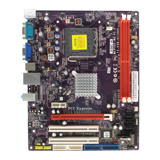
Page 10: Motherboard Components
Motherboard Components Introducing the Motherboard... - Page 11 Table of Motherboard Components LABEL COMPONENTS ® LGA775 socket for Intel Core 2 Quad*/Core 1. CPU Socket ® ® ® Duo/Pentium D*/Pentium 4*/Celeron D CPUs 2. CPU_FAN CPU cooling fan connector 3. DDR2_1~2 240-pin DDR2 SDRAM slots 4. ATX_POWER Standard 24-pin ATX pow er connector 5.
- Page 12 Memo Introducing the Motherboard...
-
Page 13: Installing The Motherboard
Chapter 2 Installing the Motherboard Safety Precautions • Follow these safety precautions when installing the motherboard • Wear a grounding strap attached to a grounded device to avoid dam- age from static electricity • Discharge static electricity by touching the metal case of a safely grounded object before working on the motherboard •... -
Page 14: Checking Jumper Settings
Do not over-tighten the screws as this can stress the motherboard. Checking Jumper Settings This section explains how to set jumpers for correct configuration of the motherboard. Setting Jumpers Use the motherboard jumpers to set system configuration options. Jumpers with more than one pin are numbered. -
Page 15: Checking Jumper Settings
Checking Jumper Settings The following illustration shows the location of the motherboard jumpers. Pin 1 is labeled. Jumper Settings Jumper Type Description Setting (default) 1-2: NORMAL 2-3: CLEAR CMOS CLR_CMOS 3-pin Clear CMOS Before clearing the CLR_CMOS CMOS, make sure to turn off the system. -
Page 16: Installing Hardware
Installing Hardware Installing the Processor Caution: When installing a CPU heatsink and cooling fan make sure that you DO NOT scratch the motherboard or any of the surface-mount resis- tors with the clip of the cooling fan. If the clip of the cooling fan scrapes across the motherboard, you may cause serious damage to the motherboard or its components. -
Page 17: Cpu Installation Procedure
CPU Installation Procedure The following illustration shows CPU installation components. A. Read and follow the instructions shown on the sticker on the CPU cap. B. Unload the cap · Use thumb & forefinger to hold the lifting tab of the cap. ·... -
Page 18: Installing Memory Modules
Installing Memory Modules This motherboard accommodates two 240-pin unbuffered DIMMs and supports DDR2 667/533 (Over spec up to 800*) DDR2 SDRAM. DDR2 SDRAM memory module table Memory module Memory Bus DDR2 266 MHz DDR2 667 333 MHz DDR2 800* 400 MHz You must install at least one module in any of the two slots. - Page 19 Table A: DDR2 (memory module) QVL (Qualified Vendor List) The following DDR2 memory modules have been tested and qualified for use with this motherboard. Type Size Vendor Module Name Aeneon AET660UD00-370A98Z Infineon HYS64T64400HU-3.7-A 512 MB Kingston KVR533D2N4/512 MEABR321LA01AA DDR2 533 Samsung M378T 6553BGO-CD 5 Infineon...
-
Page 20: Expansion Slots
Expansion Slots Installing Add-on Cards The slots on this motherboard are designed to hold expansion cards and connect them to the system bus. Expansion slots are a means of adding or enhancing the motherboard’s features and capabilities. With these efficient facilities, you can increase the motherboard’s capabilities by adding hardware that performs tasks that are not part of the basic system. - Page 21 Follow these instructions to install an add-on card: Remove a blanking plate from the system case corresponding to the slot you are going to use. Install the edge connector of the add-on card into the expansion slot. Ensure that the edge connector is correctly seated in the slot. Secure the metal bracket of the card to the system case with a screw.
-
Page 22: Connecting Optional Devices
Connecting Optional Devices Refer to the following for information on connecting the motherboard’s optional devices: F_AUDIO: Front Panel Audio header This header allows the user to install auxiliary front-oriented microphone and line- out ports for easier access. Signal Name Signal Name Signal Name Function PORT 1L... - Page 23 F_USB1~2: Front Panel USB headers The motherboard has four USB ports installed on the rear edge I/O port array. Additionally, some computer cases have USB ports at the front of the case. If you have this kind of case, use auxiliary USB connector to connect the front-mounted ports to the motherboard.
- Page 24 LPT: Onboard parallel port header This is a header that can be used to connect to the printer, scanner or other devices. Signal Name Signal Name STROBE ERROR INIT SLCTIN Ground Ground Ground Ground Ground Ground BUSK Ground Ground SLCT Installing the Motherboard...
-
Page 25: Installing A Hard Disk Drive/Cd-Rom/Sata Hard Drive
Installing a Hard Disk Drive/CD-ROM/SATA Hard Drive This section describes how to install IDE devices such as a hard disk drive and a CD- ROM drive. About IDE Devices Your motherboard has one IDE interface. An IDE ribbon cable supporting two IDE devices is bundled with the motherboard. -
Page 26: Installing A Floppy Diskette Drive
Refer to the illustration below for proper installation: Attach either cable end to the connector on the motherboard. Attach the other cable end to the SATA hard drive. Attach the SATA power cable to the SATA hard drive and connect the other end to the power supply. -
Page 27: Connecting I/O Devices
Connecting I/O Devices The backplane of the motherboard has the following I/O ports: PS2 Mouse Use the upper PS/2 port to connect a PS/2 pointing device. PS2 Keyboard Use the lower PS/2 port to connect a PS/2 keyboard. Serial Port Use the COM port to connect serial devices such as mouse (COM) or fax/modems. -
Page 28: Connecting Case Components
Connecting Case Components After you have installed the motherboard into a case, you can begin connecting the motherboard components. Refer to the following: Connect the CPU cooling fan cable to CPU_FAN. Connect the system cooling fan connector to SYS_FAN. Connect the standard power supply connector to ATX_POWER. Connect the auxiliary case power supply connector to ATX12V. -
Page 29: Atx 12V Power Connector
CPU_FAN: FAN Power Connector Signal Name Function System Ground Power +12V +12V Sense Sensor Control CPU FAN control Users please note that the fan connector supports the CPU cooling fan of 1.1A ~ 2.2A (26.4W max) at +12V. SYS_FAN: System Cooling FAN Power Connector Signal Name Function System Ground... -
Page 30: Front Panel Header
SPK: Internal speaker header Signal Name Speaker Signal Front Panel Header The front panel header (F_PANEL ) provides a standard set of switch and LED headers commonly found on ATX or Micro ATX cases. Refer to the table below for information: Signal Function... - Page 31 Power Switch Supporting the power on/off function requires connecting pins 6 and 8 to a momen- tary-contact switch that is normally open. The switch should maintain contact for at least 50 ms to signal the power supply to switch on or off. The time requirement is due to internal de-bounce circuitry.
- Page 32 Memo Installing the Motherboard...
-
Page 33: Using Bios
Chapter 3 Using BIOS About the Setup Utility The computer uses the latest “American Megatrends Inc.” BIOS with support for Windows Plug and Play. The CMOS chip on the motherboard contains the ROM setup instructions for configuring the motherboard BIOS. The BIOS (Basic Input and Output System) Setup Utility displays the system’s configuration status and provides you with options to set system parameters. -
Page 34: Using Bios
Press the delete key to access the BIOS Setup Utility. CMOS Setup Utility -- Copyright (C) 1985-2007, American Megatrends, Inc. Standard CMOS Setup Frequency/Voltage Control Advanced Setup Load Default Settings Advanced Chipset Setup Supervisor Password Integrated Peripherals User Password Power Management Setup Save &... -
Page 35: Standard Cmos Setup
For the purpose of better product maintenance, the manufacture reserves the right to change the BIOS items presented in this manual. The BIOS setup screens shown in this chapter are for reference only and may differ from the actual BIOS. Please visit the manufacture’s website for updated manual. Standard CMOS Setup This option displays basic information about your system. - Page 36 Type (Auto) Use this item to configure the type of the IDE device that you specify. If the feature is enabled, it will enhance hard disk performance by reading or writing more data during each transfer. LBA/Large Mode (Auto) Use this item to set the LAB/Large mode to enhance hard disk performance by optimizing the area the hard disk is visited each time.
-
Page 37: Advanced Setup
Advanced Setup This page sets up more advanced information about your system. Handle this page with caution. Any changes can affect the operation of your computer. CMOS Setup Utility - Copyright (C) 1985-2007, American Megatrends, Inc. Advanced Setup Thermal Management Enabled Help Item TM Status... - Page 38 Boot Up Numlock Status (On) This item defines if the keyboard Num Lock key is active when your system is started. APIC Mode (Enabled) This item allows you to enable or disable the APCI (Advanced Programmable Inter- rupt Controller) mode. APIC provides symmetric multi-processing (SMP) for sys- tems, allowing support for up to 60 processors.
-
Page 39: Advanced Chipset Setup
Advanced Chipset Setup This page sets up more advanced information about your system. Handle this page with caution. Any changes can affect the operation of your computer. CMOS Setup Utility - Copyright (C) 1985-2007, American Megatrends, Inc. Advanced Chipset Setup Memory Timings Auto Help Item... -
Page 40: Integrated Peripherals
Integrated Peripherals This page sets up some parameters for peripheral devices connected to the system. CMOS Setup Utility - Copyright (C) 1985-2007, American Megatrends, Inc. Integrated Peripherals Onboard IDE Controller Enabled Help Item OnChip S-ATA Controller Enabled SATA Mode Select SATA Mode Onboard Audio Function Enabled... -
Page 41: Power Management Setup
Parallel Port Address (378) Use this item to enable or disable the onboard Parallel port, and to assign a port address. Parallel Port Mode (ECP) Use this item to set the parallel port mode. You can select Normal (Standard Parallel Port), ECP (Extended Capabilities Port), EPP (Enhanced Parallel Port), or EPP &... - Page 42 Soft-Off By PWR-BTTN (Instant Off) Under ACPI (Advanced Configuration and Power management Interface) you can create a software power down. In a software power down, the system can be resumed by Wake Up Alarms. This item lets you install a software power down that is con- trolled by the power button on your system.
-
Page 43: Pci/Pnp Configuration
PCI / PnP Configuration This page sets up some parameters for devices installed on the PCI bus and those utilizing the system plug and play capability. CMOS Setup Utility - Copyright (C) 1985-2007, American Megatrends, Inc. PCI / PnP Setup Help Item Init Display First Options... - Page 44 Smart Fan Function Scroll to this item and press <Enter> to view the following screen: CMOS Setup Utility - Copyright (C) 1985-2007, American Megatrends, Inc. Smart Fan Function Help Item SMART Fan Control Disabled Options Disabled Enabled : Move Enter : Select +/-/: Value F10: Save ESC: Exit...
-
Page 45: Frequency/Voltage Control
Frequency/Voltage Control This page enables you to set the clock speed and system bus for your system. The clock speed and system bus are determined by the kind of processor you have in- stalled in your system. CMOS Setup Utility - Copyright (C) 1985-2007, American Megatrends, Inc. Frequency/Voltage Control Help Item Manufacturer: Intel... -
Page 46: Load Default Settings
NB Voltage (1.349V) This item allows users to adjust the Northbridge voltage. Press <Esc> to return to the main menu setting page. Load Default Settings This option opens a dialog box to ask if you are sure to install optimized defaults or not. -
Page 47: User Password
User Password This page helps you install or change a password. CMOS Setup Utility - Copyright (C) 1985-2007, American Megatrends, Inc. User Password User Password : Not Installed Help Item : Move Enter : Select +/-/: Value F10: Save ESC: Exit F1:General Help F9: Optimized Defaults User Password (Not Installed) -
Page 48: Updating The Bios
Updating the BIOS You can download and install updated BIOS for this motherboard from the manufacturer’s Web site. New BIOS provides support for new peripherals, improve- ments in performance, or fixes for known bugs. Install new BIOS as follows: If your motherboard has a BIOS protection jumper, change the setting to allow BIOS flashing. -
Page 49: Using The Motherboard Software
Chapter 4 Using the Motherboard Software About the Software CD-ROM The support software CD-ROM that is included in the motherboard package contains all the drivers and utility programs needed to properly run the bundled products. Below you can find a brief description of each software program, and the location for your motherboard version. -
Page 50: Running Setup
Setup Tab Setup Click the Setup button to run the software installation program. Select from the menu which software you want to install. Browse CD The Browse CD button is the standard Windows command that al- lows you to open Windows Explorer and show the contents of the support CD. - Page 51 Click Next. The following screen appears: Check the box next to the items you want to install. The default options are recom- mended. Click Next run the Installation Wizard. An item installation screen appears: Follow the instructions on the screen to install the items. 1.
- Page 52 Method 1. Run Reboot Setup Windows Vista will block startup programs by default when installing drivers after the system restart. You must select taskbar icon Run Blocked Program and run Reboot Setup to install the next driver, until you finish all drivers installation. Method 2.
- Page 53 Select Classic View. Set User Account. Select Turn User Account Control on or off and press Continue. Using the Motherboard Software...
-
Page 54: Manual Installation
Disable User Account Control (UAC) to help protect your computer item and press OK, then press Restart Now. Then you can restart your computer and continue to install drivers without running blocked programs. Manual Installation Insert the CD in the CD-ROM drive and locate the PATH.DOC file in the root directory. -
Page 55: Setting Up Nvidia Raid Configuration
Chapter 5 Setting Up NVIDIA RAID Configuration There are two ways to setup NVIDIA RAID Configuration: one is to create a RAID 1 Array for backup or a RAID 0 Array for increased performance just by adding additional disk array without changing the original OS (Non-Bootable RAID Array); while the other is to configure the RAID Array disks when reinstalling the OS (Bootable RAID Array). - Page 56 From the Integrated Peripherals Window, globally set SATA Mode select to RAID Mode (see Figure 1.2). Press F10 to save the configuration and exit (F10 is the navigation key to save the current configuration and exit setup in BIOS setting). The PC reboots.
-
Page 57: Setting Up A Bootable Raid Array
Setting Up a Bootable RAID Array This section explains how to configure a bootable NVIDIA RAID array. Setting Up the BIOS Start your computer, then press Delete to enter the BIOS setup. The BIOS CMOS Setup Utility screen appears. Figure 1.4 BIOS CMOS Setup Utility Main Screen Use the arrow keys to select Integrated Peripherals (see Figure 1.4), then press Enter. -
Page 58: Configuring The Nvidia Raid Bios
Press F10 to save the configuration and exit. The PC reboots. Enter the RAID BIOS Setup by pressing F10 when prompted, and pro- ceed to set up the NVIDIA RAID BIOS as described in the next section. Configuring the NVIDIA RAID BIOS The NVIDIA RAID BIOS set up lets you choose the RAID type and which hard drives you want to make part of the array. -
Page 59: Assigning The Disks
The NVIDIA RAID Utility—Define a New Array screen appears (Figure 1.7). Figure 1.7 MediaShield BIOS By default, RAID Mode is set to Mirroring and Striping Block is set to Optimal. Using the Define a New Array Screen If necessary, press the tab key to move from field to field until the appropriate field is highlighted. - Page 60 Figure 1.8 illustrates the Define a New Array screen after one disk have been assigned as RAID 0 array disk. Figure 1.8 MediaShield BIOS—Array Disks Assigned Completing the RAID BIOS Setup After assigning your RAID array disk, press F7. The Clear disk array prompt appears. Figure 1.9 Clear Disk Data Prompt NVIDIA RAID Configuration...
- Page 61 Press Y to clear the disk data. The Array List screen appears, where you can review the RAID arrays that you have set up. Figure 1.10 Array List Window Use the arrow keys to select the array that you want to set up, then press B to specify the array as bootable.
- Page 62 Installing the RAID Drivers Your system may come with a Windows install CD that already includes NVIDIA RAID drivers. If so, then this section is not relevant. If that is not the case (or you are trying to install a new version of Windows), then you will need an NVIDIA RAID driver F6 install floppy.
- Page 63 Select “NVIDIA RAID CLASS DRIVER (required)” and then press Enter. Press S again at the Specify Devices screen, then press Enter. Select “NVIDIA NForce Storage Controller (required)” and then press Enter. The following Windows Setup screen appears listing both drivers:. Figure 1.13 Windows Setup—NVIDIA drives listed Press Enter to continue with Windows XP Installation.
- Page 64 Memo NVIDIA RAID Configuration...
Need help?
Do you have a question about the GF7050VT-M5 and is the answer not in the manual?
Questions and answers