Table of Contents
Advertisement
Advertisement
Table of Contents

Subscribe to Our Youtube Channel
Related Manuals for ECS GF8100VM-M5


Summary of Contents for ECS GF8100VM-M5
- Page 3 Preface Copyright This publication, including all photographs, illustrations and software, is protected under international copyright laws, with all rights reserved. Neither this manual, nor any of the material contained herein, may be reproduced without written consent of the author. Version 1.0 Disclaimer The information in this document is subject to change without notice.
-
Page 4: Declaration Of Conformity
Declaration of Conformity This device complies with part 15 of the FCC rules. Operation is subject to the following conditions: • This device may not cause harmful interference, and • This device must accept any interference received, including interfer- ence that may cause undesired operation Canadian Department of Communications This class B digital apparatus meets all requirements of the Canadian Interference- causing Equipment Regulations. -
Page 5: Table Of Contents
T T T T T ABLE OF CONTENTS ABLE OF CONTENTS ABLE OF CONTENTS ABLE OF CONTENTS ABLE OF CONTENTS Preface Chapter 1 Introducing the Motherboard Introduction..................1 Feature ....................2 Motherboard Components.............5 7 7 7 7 7 Chapter 2 Installing the Motherboard Safety Precautions................7 Choosing a Computer Case..............7 Installing the Motherboard in a Case.. - Page 6 Integrated Peripherals............35 Power Management Setup.............36 PCI/PNP Configuration............38 PC Health Status..............39 Frequency Voltage Control............41 Load Default Setting.............42 Supervisor Passwor..............42 User Passwor................43 Save & Exit Setup..............43 Exit Without Saving..............43 45 45 45 45 Chapter 4 Using the Motherboard Software About the Software CD-ROM...............45 Auto-installing under Windows XP/Vista........45 Running Setup..............46 Manual Installation................50...
-
Page 7: Introducing The Motherboard
Chapter 1 Introducing the Motherboard Introduction Thank you for choosing the GF8100VM-M5 motherboard. This motherboard is a high performance, enhanced function motherboard that supports socket for Phenom processor (socket AM2+)/AMD Athlon 64 X2 Dual Core/Athlon Sempron processors for high-end business or personal desktop markets. -
Page 8: Feature
Feature Processor This motherboard uses a socket AM2+/AM2 that carries the following features: • Accommodates AMD Phenom processor (socket AM2+) AMD Athlon 64 X2 Dual Core/Athlon 64/Sempron processors • Supports HyperTransport (HT) 3.0 interface speeds HyperTransport Technology is a point-to-point link between two devices, it enables integrated circuits to exchange information at much higher speeds than currently available interconnect technologies. - Page 9 Audio (Optional) The onboard Audio provides either of the following features: • 7.1 Channel High Definition Audio Codec • Exceeds Microsoft Windows Logo Program (WLP) Require- ments • ADCs support 44.1K/48K/96K/192KHz sample rate • Power Support: Digital: 3.3V; Analog: 5.0V •...
- Page 10 BIOS Firmware The motherboard uses AMI BIOS that enables users to configure many system features including the following: • Power management • Wake-up alarms • CPU parameters • CPU and memory timing The firmware can also be used to set parameters for different processor clock speeds.
-
Page 11: Motherboard Components
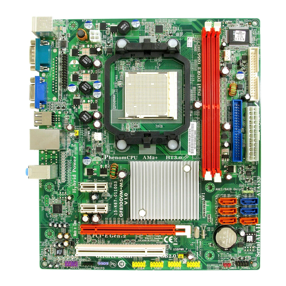
Motherboard Components Introducing the Motherboard... - Page 12 Table of Motherboard Components LABEL C O MPO NENTS Socket for AMD P henom processor (socket AM2+)/AMD 1. CP U Socket Athlon 64 X2 Dual Core/At hlon 64/Sempron processors 2. DDR2_1~2 240-pin DDR2 SDRAM slots 3. CP U_FAN CP U cooling fan connector 4.
-
Page 13: Installing The Motherboard
Chapter 2 Installing the Motherboard Safety Precautions • Follow these safety precautions when installing the motherboard • Wear a grounding strap attached to a grounded device to avoid dam- age from static electricity • Discharge static electricity by touching the metal case of a safely grounded object before working on the motherboard •... -
Page 14: Checking Jumper Settings
Do not over-tighten the screws as this can stress the motherboard. Checking Jumper Settings This section explains how to set jumpers for correct configuration of the motherboard. Setting Jumpers Use the motherboard jumpers to set system configuration options. Jumpers with more than one pin are numbered. -
Page 15: Checking Jumper Settings
Checking Jumper Settings The following illustration shows the location of the motherboard jumpers. Pin 1 is labeled. Jumper Settings Jumper Type Description Setting (default) 1-2: NORMAL 2-3: CLEAR CLR_CMOS 3-pin CLEAR CMOS Before clearing the CMOS, make sure to CLR_CMOS turn the system off. -
Page 16: Installing Hardware
Installing Hardware Installing the Processor Caution: When installing a CPU heatsink and cooling fan make sure that you DO NOT scratch the motherboard or any of the surface-mount resis- tors with the clip of the cooling fan. If the clip of the cooling fan scrapes across the motherboard, you may cause serious damage to the motherboard or its components. -
Page 17: Cpu Installation Procedure
CPU Installation Procedure The following illustration shows CPU installation components. Unhook the locking lever of the CPU socket. Pull the locking lever away from the socket and raising it to the upright position. Match the pin1 corner marked as the beveled edge on the CPU with the pin1 corner on the socket. -
Page 18: Installing Memory Modules
Installing Memory Modules This motherboard accommodates two memory modules. It can support two 240-pin DDR2 1066 (AM2+)/800/667/533/400. The total memory capacity is 16 GB*. DDR2 SDRAM memory module table Memory module Memory Bus DDR2 200 MHz DDR2 266 MHz DDR2 333 MHz DDR2 400 MHz... - Page 19 Table A: Unbuffered DIMM Support for Socket AM2+/AM2 CPU Output Driver DRAM Timing Address Timing DIMM1 DIMM2 Compensation Speed Mode Control Register Control Register DDR2-400 002F_2F2Fh X011_1222h DDR2-400 002F_2F2Fh X011_1322h DDR2-533 002F_2F2Fh X011_1222h SRx16 SRx16 SRx16 SRx8 DDR2-533 002F_2F2Fh X011_1322h SRx8 SRx16 DDR2-533...
- Page 20 Table B: DDR2 (memory module) QVL (Qualified Vendor List) The following DDR2 1066 (AM2+)/800/667/533/400 memory modules have been tested and qualified for use with this motherboard. Type Size Vendor Module Name Corsair VC256MB533D24PB11D 9C HM Nanya Nanya NT5TU32M16AG-37B 256 MB 5PB42 D9DCD Ramaxel Elpida E5116AF-5C-E...
- Page 21 Type Size Vendor Module Name Infineon HYS64T325001HU-3-A 256 MB Ramaxel 5NB31 D9DCG A-DATA AD29608A88-3EG VALUESELECT 32M8CEC Corsair 64M8CFE PS1000545 Corsair K4T51083QC GEIL GL2L64M088BA18W 512 MB Ramaxel 5LB31 D9DCL Samsung K4T51083QC SyncMAX 04400WB01 R050008A DDR2 667 T ranscend JetRam J12Q3AB-6 Twinmos TMM6208G8M30B Elpida AM4B5708GEWS7E-0637F Apacer...
-
Page 22: Expansion Slots
Expansion Slots Installing Add-on Cards The slots on this motherboard are designed to hold expansion cards and connect them to the system bus. Expansion slots are a means of adding or enhancing the motherboard’s features and capabilities. With these efficient facilities, you can increase the motherboard’s capabilities by adding hardware that performs tasks that are not part of the basic system. - Page 23 Follow these instructions to install an add-on card: Remove a blanking plate from the system case corresponding to the slot you are going to use. Install the edge connector of the add-on card into the expansion slot. Ensure that the edge connector is correctly seated in the slot. Secure the metal bracket of the card to the system case with a screw.
-
Page 24: Connecting Optional Devices
Connecting Optional Devices Refer to the following for information on connecting the motherboard’s optional devices: F_AUDIO: Front Panel Audio header This header allows the user to install auxiliary front-oriented microphone and line- out ports for easier access. Signal Name Signal Name Signal Name Function PORT 1L... - Page 25 F_USB1~4: Front Panel USB headers The motherboard has four USB ports installed on the rear edge I/O port array. Additionally, some computer cases have USB ports at the front of the case. If you have this kind of case, use auxiliary USB connector to connect the front-mounted ports to the motherboard.
- Page 26 LPT2: Onboard parallel port header This is a header that can be used to connect to the printer, scanner or other devices. Signal Name Signal Name STROBE ERROR INIT SLCTIN Ground Ground Ground Ground Ground Ground BUSK Ground Ground SLCT Installing the Motherboard...
-
Page 27: Installing A Hard Disk Drive/Cd-Rom/Sata Hard Drive
Installing a Hard Disk Drive/CD-ROM/SATA Hard Drive This section describes how to install IDE devices such as a hard disk drive and a CD- ROM drive. About IDE Devices Your motherboard has one IDE interface. An IDE ribbon cable supporting two IDE devices is bundled with the motherboard. -
Page 28: Installing A Floppy Diskette Drive
Refer to the illustration below for proper installation: Attach either cable end to the connector on the motherboard. Attach the other cable end to the SATA hard drive. Attach the SATA power cable to the SATA hard drive and connect the other end to the power supply. -
Page 29: Connecting I/O Devices
Connecting I/O Devices The backplane of the motherboard has the following I/O ports: PS2 Mouse Use the upper PS/2 port to connect a PS/2 pointing device. PS2 Keyboard Use the lower PS/2 port to connect a PS/2 keyboard. Serial Port Use the COM port to connect serial devices such as mice or (COM) fax/modems. -
Page 30: Connecting Case Components
Connecting Case Components After you have installed the motherboard into a case, you can begin connecting the motherboard components. Refer to the following: Connect the CPU cooling fan cable to CPU_FAN. Connect the system cooling fan connector to SYS_FAN. Connect the standard power supply connector to ATX_POWER. Connect the auxiliary case power supply connector to ATX12V. - Page 31 CPU_FAN: CPU cooling FAN Power Connector Signal Name Function System Ground Power +12V +12V Sense Sensor Control CPU FAN control SYS_FAN: System cooling FAN Power Connector Users please note that the fan connector supports the CPU cooling fan of 1.1A ~ 2.2A (26.4W max) at +12V. Signal Name Function System Ground...
-
Page 32: Front Panel Header
Front Panel Header The front panel header (F_PANEL) provides a standard set of switch and LED headers commonly found on ATX or Micro ATX cases. Refer to the table below for information: Signal Function Signal Function HD_LED_P Hard disk LED (+) 2 FP PWR/SLP *MSG LED (+) HD_LED_N Hard disk LED (-) FP PWR/SLP *MSG LED (-) -
Page 33: Using Bios
Chapter 3 Using BIOS About the Setup Utility The computer uses the latest “American Megatrends Inc. ” BIOS with support for Windows Plug and Play. The CMOS chip on the motherboard contains the ROM setup instructions for configuring the motherboard BIOS. The BIOS (Basic Input and Output System) Setup Utility displays the system’s configuration status and provides you with options to set system parameters. -
Page 34: Bios Navigation Keys
Press DEL to enter SETUP Press the delete key to access the BIOS Setup Utility. CMOS Setup Utility -- Copyright (C) 1985-2005, American Megatrends, Inc. Standard CMOS Setup Frequency/Voltage Control Advanced Setup Load Default Settings Advanced Chipset Setup Supervisor Password Integrated Peripherals User Password Power Management Setup... -
Page 35: Updating The Bios
Updating the BIOS You can download and install updated BIOS for this motherboard from the manufacturer’s Web site. New BIOS provides support for new peripherals, improve- ments in performance, or fixes for known bugs. Install new BIOS as follows: If your motherboard has a BIOS protection jumper, change the setting to allow BIOS flashing. -
Page 36: Standard Cmos Setup
Standard CMOS Setup This option displays basic information about your system. CMOS Setup Utility -- Copyright (C) 1985-2005, American Megatrends, Inc. Standard CMOS Setup Date Tue 07/04/2008 Help Item Time 17:41:06 User [Enter], [TAB] Primary IDE Master Not Detected or [SHIFT-TAB] to Primary IDE Slave Not Detected select a field. - Page 37 IDE Devices Your computer has one IDE channel which can be installed with one or two devices (Master and Slave). In addition, this motherboard supports six SATA channels and each channel allows one SATA device to be installed. Use these items to configure each device on the IDE channel.
-
Page 38: Advanced Setup
Advanced Setup This page sets up more advanced information about your system. Handle this page with caution. Any changes can affect the operation of your computer. CMOS Setup Utility - Copyright (C) 1985-2005, American Megatrends, Inc. Advanced Setup Help Item HT Frequency Auto Auto AMD C&Q... -
Page 39: Advanced Chipset Setup
Removable Drives (Press Enter) Scroll to this item and press <Enter> to view the following screen: CMOS Setup Utility - Copyright (C) 1985-2005, American Megatrends, Inc. Removable Drives Help Item Removable Drives 1st Drive 1st FLOPPY DRIVE Specifies the boot sequence from the available devices. - Page 40 DRAM Frequency This item enables users to adjust the DRAM frequency. The default setting is auto and we recommend users leave the setting unchanged. Modify it at will may cause the system to be unstable. DRAM Timing Mode This item allows you to enable or disable the DRAM timing defined by the Serial Presence Detect electrical.
-
Page 41: Integrated Peripherals
Integrated Peripherals This page sets up some parameters for peripheral devices connected to the system. CMOS Setup Utility - Copyright (C) 1985-2005, American Megatrends, Inc. Integrated Peripherals Onboard IDE Controller Enabled Help Item OnChip S-ATA Controller Enabled SATA Mode select SATA Mode Onboard AUDIO Function Enabled... -
Page 42: Power Management Setup
Parallel Port IRQ (IRQ7) Use this item to assign IRQ to the parallel port. USB Controller (Enabled) Use this item to enable or disable the USB function. Legacy USB Support (Enabled) Use this item to enable or disable support for legacy USB devices. Press <Esc>... - Page 43 Resume By PCI/PCI-E/Lan PME (Disabled) The system can be turned off with a software command. If you enable this item, the system can automatically resume if there is an incoming call on the PCI Modem or PCI LAN card. You must use an ATX power supply in order to use this feature. Use this item to do wake-up action if inserting the PCI card.
-
Page 44: Pci/Pnp Configuration
PCI / PnP Setup This page sets up some parameters for devices installed on the PCI bus and those utilizing the system plug and play capability. CMOS Setup Utility - Copyright (C) 1985-2005, American Megatrends, Inc. PCI / PnP Setup Help Item iGPU and Ext-VGA Selection Single... -
Page 45: Pc Health Status
PC Health Status On motherboards support hardware monitoring, this item lets you monitor the parameters for critical voltages, temperatures and fan speeds. CMOS Setup Utility - Copyright (C) 1985-2005, American Megatrends, Inc. PC Health Status Help Item Hardware Health Event Monitoring Smart Fan Function Press Enter ShutDown Temperature... - Page 46 ShutDown Temperature (Disabled) Enable you to set the maximum temperature the system can reach before powering down. System Component Characteristics These items display the monitoring of the overall inboard hardware health events, such as System & CPU temperature, CPU & DIMM voltage, CPU & system fan speed,...etc.
-
Page 47: Frequency Voltage Control
Frequency/Voltage Control This page enables you to set the clock speed and system bus for your system. The clock speed and system bus are determined by the kind of processor you have in- stalled in your system. CMOS Setup Utility - Copyright (C) 1985-2005, American Megatrends, Inc. Frequency/Voltage Control Help item Auto Detect DIMM/PCI CIK... -
Page 48: Load Default Setting
Load Default Settings This option opens a dialog box to ask if you are sure to install optimized defaults or not. You select [OK], and then <Enter>, the Setup Utility loads all default values; or select [Cancel], and then <Enter>, the Setup Utility does not load default values. Supervisor Password This page helps you install or change a password. -
Page 49: User Passwor
User Password This page helps you install or change a password. CMOS Setup Utility - Copyright (C) 1985-2005, American Megatrends, Inc. User Password User Password : Not Installed Help item < > : Move Enter : Select +/-/: Value F10: Save ESC: Exit F1: General Help F9: Load Default settings User Password (Not Installed) - Page 50 Memo Using BIOS...
-
Page 51: Using The Motherboard Software
Chapter 4 Using the Motherboard Software About the Software CD-ROM The support software CD-ROM that is included in the motherboard package contains all the drivers and utility programs needed to properly run the bundled products. Below you can find a brief description of each software program, and the location for your motherboard version. -
Page 52: Running Setup
Setup Tab Setup Click the Setup button to run the software installation program. Select from the menu which software you want to install. Browse CD The Browse CD button is the standard Windows command that allows you to open Windows Explorer and show the contents of the support CD. - Page 53 Click Next. The following screen appears: Check the box next to the items you want to install. The default options are recom mended. Click Next run the Installation Wizard. An item installation screen appears: Follow the instructions on the screen to install the items. 1.
- Page 54 Method 1. Run Reboot Setup Windows Vista will block startup programs by default when installing drivers after the system restart. You must select taskbar icon Run Blocked Program and run Reboot Setup to install the next driver, until you finish all drivers installation. Method 2.
- Page 55 Select Classic View. Set User Account. Select Turn User Account Control on or off and press Continue. Using the Motherboard Software...
-
Page 56: Manual Installation
These software(s) are subject to change at anytime without prior notice. Please refer to the support CD for available software. Please go to ECS website to download AMD Cool’n’Quiet technology. This concludes chapter 4. Using the Motherboard Software... -
Page 57: Setting Up Nvidia Raid Configuration
Chapter 5 Setting Up NVIDIA RAID Configuration There are two ways to setup NVIDIA RAID Configuration: one is to create a RAID 1 Array for backup or a RAID 0 Array for increased performance just by adding additional disk array without changing the original OS (Non-Bootable RAID Array); while the other is to configure the RAID Array disks when reinstalling the OS (Bootable RAID Array). - Page 58 From the Integrated Peripherals Window, globally set SATA Mode select to RAID Mode (see Figure 1.2). Press F10 to save the configuration and exit (F10 is the navigation key to save the current configuration and exit setup in BIOS setting). The PC reboots.
-
Page 59: Setting Up A Bootable Raid Array
Setting Up a Bootable RAID Array This section explains how to configure a bootable NVIDIA RAID array. Setting Up the BIOS Start your computer, then press Delete to enter the BIOS setup. The BIOS CMOS Setup Utility screen appears. Figure 1.4 BIOS CMOS Setup Utility Main Screen Use the arrow keys to select Integrated Peripherals (see Figure 1.4), then press Enter. - Page 60 Press F10 to save the configuration and exit. The PC reboots. Enter the RAID BIOS Setup by pressing F10 when prompted, and proceed to set up the NVIDIA RAID BIOS as described in the next section. Configuring the NVIDIA RAID BIOS The NVIDIA RAID BIOS set up lets you choose the RAID type and which hard drives you want to make part of the array.
- Page 61 The NVIDIA RAID Utility—Define a New Array screen appears (Figure 1.7). Figure 1.7 MediaShield BIOS By default, RAID Mode is set to Mirroring and Striping Block is set to Optimal. Using the Define a New Array Screen If necessary, press the tab key to move from field to field until the appropriate field is highlighted.
- Page 62 Figure 1.8 illustrates the Define a New Array screen after one disk have been assigned as RAID 0 array disk. Figure 1.8 MediaShield BIOS—Array Disks Assigned Completing the RAID BIOS Setup After assigning your RAID array disk, press F7. The Clear disk array prompt appears. Figure 1.9 Clear Disk Data Prompt NVIDIA RAID Configuration...
- Page 63 Press Y to clear the disk data. The Array List screen appears, where you can review the RAID arrays that you have set up. Figure 1.10 Array List Window Use the arrow keys to select the array that you want to set up, then press B to specify the array as bootable.
- Page 64 Installing the RAID Drivers Your system may come with a Windows install CD that already includes NVIDIA RAID drivers. If so, then this section is not relevant. If that is not the case (or you are trying to install a new version of Windows), then you will need an NVIDIA RAID driver F6 install floppy.
- Page 65 Select “NVIDIA RAID CLASS DRIVER (required)” and then press Enter. Press S again at the Specify Devices screen, then press Enter. Select “NVIDIA NForce Storage Controller (required)” and then press Enter. The following Windows Setup screen appears listing both drivers:. Figure 2.15 Windows Setup—NVIDIA drives listed Press Enter to continue with Windows XP Installation.
- Page 66 Memo NVIDIA RAID Configuration...
-
Page 67: Nvidia Hybrid Sli Technology Support
Chapter 6 ® ® ® ® ® ® ® ® ® ® NVIDIA Hybrid SLI Technology Support This motherboard supports the NVIDIA® Hybrid SLI® Technology. Hybrid SLI® technology, based on NVIDIA’s industry-leading SLI technology, deliv- ers multi-GPU (graphics processing unit) benefits when an NVIDIA® motherboard GPU is combined with an NVIDIA discrete GPU. -
Page 68: Hybrid Sli Products
Hybrid SLI products Hybrid SLI Enabled Motherboard GPUs Hybrid Power GeForce Boost Technology Technology GeForce 8300 GeForce 8200 GeForce 8100 nForce 730a nForce 720a Hybrid SLI Enabled Graphics Card GeForce Boost Technology HybridPower Technology Х GeForce GTX 280 Х GeForce 9800 GX2 Х... -
Page 69: Hybrid Requirements And Constraints
2 × 1024 MB of DDR2-800 DRAM • Discrete GPU recommended for GeForce Boost Visit the ECS website (www.ecs.com.tw) for for more information of this motherboard. Make sure that your graphics card driver supports the NVIDIA® Hybrid SLI® Technology. Download the latest driver from the NVIDIA website (www.nvidia.com). -
Page 70: Installation And Use
Installation and Use 1. Prepare one Hybrid SLI enabled graphics card. Insert the Hybrid SLI enabled graphics card into the PCIEX16 Slot on the motherboard. Start your computer, then press Delete to enter the BIOS setup; use the arrow keys to select Advanced Chipset Setup, then press Enter;... - Page 71 Enter Window Vista to install the latest driver which supports the NVIDIA Hybrid SLI technology. Restart your computer after installing the driver. You can see the green icon of NVIDIA Hybrid SLI in the bottom right-hand corner while accessing the Windows Vista again.
- Page 72 Click with your right mouse button on My Computer, then click the option Man- age and choose the Device Manager, finally, click the Display Adapters. The following screen appears. All in all, the NVIDIA SLI technology works. This concludes Chapter 6. NVIDIA®...
Need help?
Do you have a question about the GF8100VM-M5 and is the answer not in the manual?
Questions and answers