Table of Contents
Advertisement
Advertisement
Table of Contents

Related Manuals for ECS GF8200A


Summary of Contents for ECS GF8200A
- Page 3 Preface Copyright This publication, including all photographs, illustrations and software, is protected under international copyright laws, with all rights reserved. Neither this manual, nor any of the material contained herein, may be reproduced without written consent of the author. Version 1.0A Disclaimer The information in this document is subject to change without notice.
-
Page 4: Declaration Of Conformity
Declaration of Conformity This device complies with part 15 of the FCC rules. Operation is subject to the following conditions: • This device may not cause harmful interference, and • This device must accept any interference received, including interfer- ence that may cause undesired operation Canadian Department of Communications This class B digital apparatus meets all requirements of the Canadian Interference- causing Equipment Regulations. -
Page 5: Table Of Contents
T T T T T ABLE OF CONTENTS ABLE OF CONTENTS ABLE OF CONTENTS ABLE OF CONTENTS ABLE OF CONTENTS Preface Chapter 1 Introducing the Motherboard Introduction..................1 Feature ....................2 Motherboard Components.............5 7 7 7 7 7 Chapter 2 Installing the Motherboard Safety Precautions................7 Choosing a Computer Case............7 Installing the Motherboard in a Case..........7... - Page 6 Integrated Peripherals............36 Power Management Setup..........37 PCI/PNP Configuration.............39 PC Health Status..............40 M.I.B (MB Intelligent BIOS)..........41 Load Default Settings............44 Supervisor Password............44 User Password..............45 Save & Exit Setup..............45 Exit Without Saving............45 Updating the BIOS.............46 47 47 47 47 47 Chapter 4 Using the Motherboard Software About the Software CD-ROM...............47 Auto-installing under Windows XP/Vista........47 Running Setup..............48...
-
Page 7: Introducing The Motherboard
Chapter 1 Introducing the Motherboard Introduction Thank you for choosing the GF8200A motherboard. This motherboard is a high performance, enhanced function motherboard that supports socket for Phenom processor (socket AM2+)/AMD Athlon 64 X2 Dual-Core/Athlon Sempron processors for high-end business or personal desktop markets. ®... -
Page 8: Feature
Feature Processor This motherboard uses a socket AM2+/AM2 that carries the following features: • Accommodates AMD Phenom processor (socket AM2+) AMD Athlon 64 X2 Dual-Core/Athlon 64/Sempron processors • Supports HyperTransport (HT) 3.0 interface speeds HyperTransport Technology is a point-to-point link between two devices, it enables integrated circuits to exchange information at much higher speeds than currently available interconnect technologies. - Page 9 Audio (Optional) The onboard Audio provides either of the following features: • 5.1 Channel High Definition Audio Codec • DACs Support 96K/48K/44.1KHz DAC sample rate • Power support: Digital:3.3V; Analog:5.0V • and Tru Surround from SRS • Provides single ended CD input with DRM solutions and legacy OS issues •...
- Page 10 Integrated I/O The motherboard has a full set of I/O ports and connectors: • Two PS/2 ports for mouse and keyboard • One VGA port • One HDMI port • One eSATA port • Six USB ports • One LAN port •...
-
Page 11: Motherboard Components
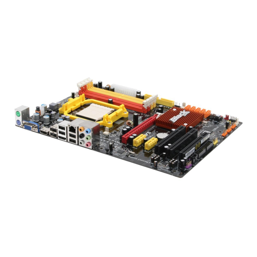
Motherboard Components Introducing the Motherboard... - Page 12 Table of Motherboard Components LABEL CO MPO NENTS Socket for AMD Phenom processor (socket AM2+)/AMD 1. CPU Socket Athlon 64 X2 Dual-Core/Athlon 64/Sempron processors 2. CPU_FAN CPU cooling fan connector 3. DDR2_1~4 240-pin DDR2 SDRAM slots 4. AT X_POWER Standard 24-Pin AT X Power connector 5.
-
Page 13: Installing The Motherboard
Chapter 2 Installing the Motherboard Safety Precautions • Follow these safety precautions when installing the motherboard • Wear a grounding strap attached to a grounded device to avoid dam- age from static electricity • Discharge static electricity by touching the metal case of a safely grounded object before working on the motherboard •... -
Page 14: Checking Jumper Settings
Do not over-tighten the screws as this can stress the motherboard. Checking Jumper Settings This section explains how to set jumpers for correct configuration of the motherboard. Setting Jumpers Use the motherboard jumpers to set system configuration options. Jumpers with more than one pin are numbered. -
Page 15: Checking Jumper Settings
Checking Jumper Settings The following illustration shows the location of the motherboard jumpers. Pin 1 is labeled. Jumper Settings Jumper Type Description Setting (default) 1-2: NORMAL 2-3: CLEAR CLR_CMOS 3-pin CLEAR CMOS Before clearing the CMOS, make sure to CLR_CMOS turn the system off. -
Page 16: Installing Hardware
Installing Hardware Installing the Processor Caution: When installing a CPU heatsink and cooling fan make sure that you DO NOT scratch the motherboard or any of the surface-mount resis- tors with the clip of the cooling fan. If the clip of the cooling fan scrapes across the motherboard, you may cause serious damage to the motherboard or its components. -
Page 17: Installing Memory Modules
CPU Installation Procedure The following illustration shows CPU installation components. Unhook the locking lever of the CPU socket. Pull the locking lever away from the socket and raising it to the upright position. Match the pin1 corner marked as the beveled edge on the CPU with the pin1 corner on the socket. -
Page 18: Installation Procedure
Installation Procedure Refer to the following to install the memory modules. This motherboard supports unbuffered DDR2 SDRAM only. Push the latches on each side of the DIMM slot down. Align the memory module with the slot. The DIMM slots are keyed with notches and the DIMMs are keyed with cutouts so that they can only be installed correctly. - Page 19 Table A: DDR2 (memory module) QVL (Qualified Vendor List) The following DDR2 1066 (AM2+)/800/667/533/400 memory modules have been tested and qualified for use with this motherboard. Type Size Vendor Module Name Hynix HYMP532U646-E3 AA 256 MB DDR2 400 Nanya NT512T64U88A0F-5A 512 MB Elixir M2U25664TUH4A0F-37B...
- Page 20 Type Size Vendor Module Name Infineon HYS64T32000HU-25F-B 256 MB A-DATA M2OAD6G3H3160I1E53 Aeneon AET660UD00-25DB98X APOGEE AU51082-800P505 Infineon HYS64T64000HU-25F-B Infinity 04751208CZ5U2D 512 MB Kingston KHX6400D2ULK2/1G Kingston KVR800D2N5/512 Micron MT8HTF6464AY-80ED4 Nanya NT512T64U88B0BY-25C AL6E8E63H-8E1 Aeneon AET760UD00-25DC08X Aeneon AET860UD00-25DC08X Apacer 78.01GA0.9K5 APOGEE AU1G082-800P000 Infineon HYS64T128020HU-25F-B Infinity 04701G16CZ5U2G DDR2 800...
- Page 21 Mem ory Type Size Vendor Module Nam e Recom m end Volt KVR1066D2N7/512 1.8V / 512 MB Kingston 1.8 V 9905315-094.A00LF Apacer 78.0AG9S.9K4 1.9 V KVR1066D2N7/1G 1.8V / Kingston 1.8 V 9905316-106.A01LF DDR2 1066 1 GB Micron MT8HTF12864AY-1GAE1 1.9 V OCZ2RPR10662GK 1.9 V ~ 2.3 V Qimonda...
-
Page 22: Expansion Slots
Expansion Slots Installing Add-on Cards The slots on this motherboard are designed to hold expansion cards and connect them to the system bus. Expansion slots are a means of adding or enhancing the motherboard’s features and capabilities. With these efficient facilities, you can increase the motherboard’s capabilities by adding hardware that performs tasks that are not part of the basic system. - Page 23 Follow these instructions to install an add-on card: Remove a blanking plate from the system case corresponding to the slot you are going to use. Install the edge connector of the add-on card into the expansion slot. Ensure that the edge connector is correctly seated in the slot. Secure the metal bracket of the card to the system case with a screw.
-
Page 24: Connecting Optional Devices
Connecting Optional Devices Refer to the following for information on connecting the motherboard’s optional devices: F_AUDIO: Front Panel Audio header This header allows the user to install auxiliary front-oriented microphone and line- out ports for easier access. Signal Name Signal Name Signal Name Function PORT 1L... - Page 25 IR: Infrared header The motherboard supports an Infrared (IR) data port. Infrared ports allow the wire- less exchange of information between your computer and similarly equipped devices such as printers, laptops, Personal Digital Assistants (PDAs), and other computers. Signal Name Function Not Assigned Not assigned...
- Page 26 CD_IN: Analog Audio Input connector Signal Name Function CD_L CD In left channel Ground Ground CD_R CD In right channel COM: Onboard serial port header Connect a serial port extension bracket to this header to add a second serial port to your system.
-
Page 27: Installing A Hard Disk Drive/Cd-Rom/Sata Hard Drive
Installing a Hard Disk Drive/CD-ROM/SATA Hard Drive This section describes how to install IDE devices such as a hard disk drive and a CD- ROM drive. About IDE Devices Your motherboard has one IDE interface. An IDE ribbon cable supporting two IDE devices is bundled with the motherboard. -
Page 28: Installing A Floppy Diskette Drive
Refer to the illustration below for proper installation: Attach either cable end to the connector on the motherboard. Attach the other cable end to the SATA hard drive. Attach the SATA power cable to the SATA hard drive and connect the other end to the power supply. -
Page 29: Connecting I/O Devices
Connecting I/O Devices The backplane of the motherboard has the following I/O ports: PS2 Mouse Use the upper PS/2 port to connect a PS/2 pointing device. PS2 Keyboard Use the lower PS/2 port to connect a PS/2 keyboard. VGA Port Connect your monitor to the VGA port. - Page 30 This motherboard may adopt 6-channel audio ports. Use the three audio ports to connect audio devices. The first jack is for stereo line-in signal. The second jack is for stereo line-out signal. The third jack is for microphone. Installing the Motherboard...
-
Page 31: Connecting Case Components
Connecting Case Components After you have installed the motherboard into a case, you can begin connecting the motherboard components. Refer to the following: Connect the CPU cooling fan cable to CPU_FAN. Connect the system cooling fan connector to SYS_FAN. Connect the standard power supply connector to ATX_POWER. Connect the auxiliary case power supply connector to ATX12V. - Page 32 Connecting 4-pin power cable The ATX12V power connector is used to provide power to the CPU. When installing 4-pin power cable, the latches of power cable and the ATX12V match perfectly. 4-pin power cable CPU_FAN: CPU cooling FAN Power Connector Signal Name Function System Ground...
- Page 33 ATX12V: ATX 12V Power Connector Signal Name Ground Ground +12V +12V SPK: Internal speaker header Signal Name Signal Installing the Motherboard...
-
Page 34: Front Panel Header
Front Panel Header The front panel header (F_PANEL) provides a standard set of switch and LED headers commonly found on ATX or Micro ATX cases. Refer to the table below for information: Signal Function Signal Function HD_LED_P Hard disk LED (+) 2 FP PWR/SLP *MSG LED (+) HD_LED_N Hard disk LED (-) FP PWR/SLP *MSG LED (-) -
Page 35: Using Bios
Chapter 3 Using BIOS About the Setup Utility The computer uses the latest “American Megatrends Inc. ” BIOS with support for Windows Plug and Play. The CMOS chip on the motherboard contains the ROM setup instructions for configuring the motherboard BIOS. The BIOS (Basic Input and Output System) Setup Utility displays the system’s configuration status and provides you with options to set system parameters. -
Page 36: Using Bios
Press the delete key to access the BIOS Setup Utility. CMOS Setup Utility -- Copyright (C) 1985-2007, American Megatrends, Inc. Standard CMOS Setup M.I.B. (MB Intelligent Bios) Advanced Setup Load Default Settings Advanced Chipset Setup Supervisor Password Integrated Peripherals User Password Power Management Setup Save &... -
Page 37: Standard Cmos Setup
For the purpose of better product maintenance, the manufacture reserves the right to change the BIOS items presented in this manual. The BIOS setup screens shown in this chapter are for reference only and may differ from the actual BIOS. Please visit the manufacture’s website for updated manual. - Page 38 Type (Auto) Use this item to configure the type of the IDE device that you specify. If the feature is enabled, it will enhance hard disk performance by reading or writing more data during each transfer. LBA/Large Mode (Auto) Use this item to set the LAB/Large mode to enhance hard disk performance by optimizing the area the hard disk is visited each time.
-
Page 39: Advanced Setup
Advanced Setup This page sets up more advanced information about your system. Handle this page with caution. Any changes can affect the operation of your computer. CMOS Setup Utility - Copyright (C) 1985-2007, American Megatrends, Inc. Advanced Setup Help Item HT Frequency Auto Auto AMD C&Q... - Page 40 Hard Disk Drives (Press Enter) Scroll to this item and press <Enter> to view the following screen: CMOS Setup Utility - Copyright (C) 1985-2007, American Megatrends, Inc. Hard Disk Drives Help Item Hard Disk Drives *1st Drive Hard Drive Specifies the boot sequence from the available devices.
-
Page 41: Advanced Chipset Setup
Advanced Chipset Setup This page sets up more advanced information about your system. Handle this page with caution. Any changes can affect the operation of your computer. CMOS Setup Utility - Copyright (C) 1985-2007, American Megatrends, Inc. Advanced Chipset Setup Help Item Hybrid SLI support Disabled... -
Page 42: Integrated Peripherals
Integrated Peripherals This page sets up some parameters for peripheral devices connected to the system. CMOS Setup Utility - Copyright (C) 1985-2007, American Megatrends, Inc. Integrated Peripherals Onboard IDE Controller Enabled Help Item OnChip S-ATA Controller Enabled SATA Mode select AHCI Mode AHCI Configuration Press Enter... -
Page 43: Power Management Setup
OnBoard AUDIO Function (Enabled) Use this item to enable or disable the onboard Audio function. OnBoard LAN Function (Enabled) Use this item to enable or disable the onboard LAN function. OnBoard LAN Boot ROM (Disabled) Use this item to enable or disable the booting from the onboard LAN or a network add-in card with a remote boot ROM installed. - Page 44 Soft-off by PWR-BTTN (Instant off) Under ACPI (Advanced Configuration and Power management Interface) you can create a software power down. In a software power down, the system can be resumed by Wake Up Alarms. This item lets you install a software power down that is con- trolled by the power button on your system.
-
Page 45: Pci/Pnp Configuration
PCI / PnP Setup This page sets up some parameters for devices installed on the PCI bus and those utilizing the system plug and play capability. CMOS Setup Utility - Copyright (C) 1985-2007, American Megatrends, Inc. PCI / PnP Setup Help Item iGPU and Ext-VGA Selection Single... -
Page 46: Pc Health Status
PC Health Status On motherboards support hardware monitoring, this item lets you monitor the parameters for critical voltages, temperatures and fan speeds. CMOS Setup Utility - Copyright (C) 1985-2007, American Megatrends, Inc. PC Health Status Help Item Hardware Health Event Monitoring Smart Fan Function Press Enter ShutDown Temperature... -
Page 47: Mb Intelligent Bios)
ShutDown Temperature (Disabled) Enable you to set the maximum temperature the system can reach before powering down. System Component Characteristics These items display the monitoring of the overall inboard hardware health events, such as System & CPU temperature, CPU & DIMM voltage, CPU & system fan speed,...etc. - Page 48 NB Clk This item shows the frequency of Northbridge clock. Auto Detect DIMM/PCI Clk (Enabled) When this item is enabled, BIOS will disable the clock signal of free DIMM/PCI slots. CPU/LDT Spread Spectrum (Enabled) If you enable spread spectrum, it can significantly reduce the EMI (Electro-Magnetic Interference) generated by CPU/LDT.
- Page 49 When using black-boxed CPU, the following screen appears. CMOS Setup Utility - Copyright (C) 1985-2007 American Megatrends, Inc. M.I.B (MB Intelligent BIOS) Help item AMD Athlon (tm) 64 X2 Dual Core Processor 5000+ Configure CPU Revision : frequency Cache L1 : 256KB Cache L2 : 1024KB...
-
Page 50: Load Default Settings
Load Default Settings This option opens a dialog box to ask if you are sure to install optimized defaults or not. You select [OK], and then <Enter>, the Setup Utility loads all default values; or select [Cancel], and then <Enter>, the Setup Utility does not load default values. Supervisor Password This page helps you install or change a password. -
Page 51: User Password
User Password This page helps you install or change a password. CMOS Setup Utility - Copyright (C) 1985-2007, American Megatrends, Inc. User Password User Password : Not Installed Help item Install or Change the password. < > : Move Enter : Select +/-/: Value F10: Save ESC: Exit F1: General Help... -
Page 52: Updating The Bios
Updating the BIOS You can download and install updated BIOS for this motherboard from the manufacturer’s Web site. New BIOS provides support for new peripherals, improve- ments in performance, or fixes for known bugs. Install new BIOS as follows: If your motherboard has a BIOS protection jumper, change the setting to allow BIOS flashing. -
Page 53: Using The Motherboard Software
Chapter 4 Using the Motherboard Software About the Software CD-ROM The support software CD-ROM that is included in the motherboard package contains all the drivers and utility programs needed to properly run the bundled products. Below you can find a brief description of each software program, and the location for your motherboard version. -
Page 54: Running Setup
Setup Tab Setup Click the Setup button to run the software installation program. Select from the menu which software you want to install. Browse CD The Browse CD button is the standard Windows command that allows you to open Windows Explorer and show the contents of the support CD. - Page 55 Click Next. The following screen appears: Check the box next to the items you want to install. The default options are recom- mended. Click Next run the Installation Wizard. An item installation screen appears: Follow the instructions on the screen to install the items. 1.
- Page 56 Method 1. Run Reboot Setup Windows Vista will block startup programs by default when installing drivers after the system restart. You must select taskbar icon Run Blocked Program and run Reboot Setup to install the next driver, until you finish all drivers installation. Method 2.
- Page 57 Select Classic View. Set User Account. Select Turn User Account Control on or off and press Continue. Using the Motherboard Software...
-
Page 58: Manual Installation
Disable User Account Control (UAC) to help protect your computer item and press OK, then press Restart Now. Then you can restart your computer and continue to install drivers without running blocked programs. Manual Installation Insert the CD in the CD-ROM drive and locate the PATH.DOC file in the root directory. -
Page 59: Hdmi Audio Setting Sop
HDMI Audio setting SOP OS: XP system 1. Control Panel-->Sound and Audio Device Properties a. Audio--> Sound playback--> Default device--> HD Auido Output b. Audio--> Sound playback--> Default device--> HDMI Auido Output a. User Playback Audio speaker function working b. User Playback HDMI speaker function working Using the Motherboard Software... - Page 60 OS: Vista system Control Panel--> Soundback--> Sound--> Digital Output Device (HDMI) --> Set Default 1. Volume --> Playback 2. Digital Output Device (HDMI) --> Set Default --> OK User HDMI Playback function working Using the Motherboard Software...
- Page 61 3. Speaker --> Set Default --> OK User Speaker Palyback function working 4. SPDIF-Out --> Set Default --> OK User SPDIF-Out Playback function working This concludes chapter 4. Using the Motherboard Software...
- Page 62 Memo Using the Motherboard Software...
-
Page 63: Setting Up Nvidia Raid Configuration
Chapter 5 Setting Up NVIDIA RAID Configuration There are two ways to setup NVIDIA RAID Configuration: One is to create a RAID 1 Array for backup or a RAID 0 Array for increased performance just by adding additional disk array without changing the original OS (Non-Bootable RAID Array); while the other is to configure the RAID Array disks when reinstalling the OS (Bootable RAID Array). - Page 64 From the Integrated Peripherals Window, globally set SATA Mode select to RAID Mode (see Figure 1.2). Press F10 to save the configuration and exit (F10 is the navigation key to save the current configuration and exit setup in BIOS setting). The PC reboots.
-
Page 65: Setting Up A Bootable Raid Array
Setting Up a Bootable RAID Array This section explains how to configure a bootable NVIDIA RAID array. Setting Up the BIOS Start your computer, then press Delete to enter the BIOS setup. The BIOS CMOS Setup Utility screen appears. Figure 1.4 BIOS CMOS Setup Utility Main Screen Use the arrow keys to select Integrated Peripherals (see Figure 1.4), then press Enter. - Page 66 Press F10 to save the configuration and exit. The PC reboots. Enter the RAID BIOS Setup by pressing F10 when prompted, and proceed to set up the NVIDIA RAID BIOS as described in the next section. Configuring the NVIDIA RAID BIOS The NVIDIA RAID BIOS set up lets you choose the RAID type and which hard drives you want to make part of the array.
- Page 67 The NVIDIA RAID Utility—Define a New Array screen appears (Figure 1.7). Figure 1.7 MediaShield BIOS By default, RAID Mode is set to Mirroring and Striping Block is set to Optimal. Using the Define a New Array Screen If necessary, press the tab key to move from field to field until the appropriate field is highlighted.
- Page 68 Figure 1.8 illustrates the Define a New Array screen after one disk have been assigned as RAID 0 array disk. Figure 1.8 MediaShield BIOS—Array Disks Assigned Completing the RAID BIOS Setup After assigning your RAID array disk, press F7. The Clear disk array prompt appears. Figure 1.9 Clear Disk Data Prompt NVIDIA RAID Configuration...
- Page 69 Press Y to clear the disk data. The Array List screen appears, where you can review the RAID arrays that you have set up. Figure 1.10 Array List Window Use the arrow keys to select the array that you want to set up, then press B to specify the array as bootable.
- Page 70 Installing the RAID Drivers Your system may come with a Windows install CD that already includes NVIDIA RAID drivers. If so, then this section is not relevant. If that is not the case (or you are trying to install a new version of Windows), then you will need an NVIDIA RAID driver F6 install floppy.
- Page 71 Select “NVIDIA RAID CLASS DRIVER (required)” and then press Enter. Press S again at the Specify Devices screen, then press Enter. Select “NVIDIA NForce Storage Controller (required)” and then press Enter. The following Windows Setup screen appears listing both drivers:. Figure 2.15 Windows Setup—NVIDIA drives listed Press Enter to continue with Windows XP Installation.
- Page 72 Memo NVIDIA RAID Configuration...
-
Page 73: Nvidia Hybrid Sli Technology Support
Chapter 6 ® ® ® ® ® ® ® ® ® ® NVIDIA Hybrid SLI Technology Support This motherboard supports the NVIDIA® Hybrid SLI® Technology. Hybrid SLI® technology, based on NVIDIA’s industry-leading SLI technology, deliv- ers multi-GPU (graphics processing unit) benefits when an NVIDIA® motherboard GPU is combined with an NVIDIA discrete GPU. -
Page 74: Hybrid Sli Products
Hybrid SLI products Hybrid SLI Enabled Motherboard GPUs Hybrid Power GeForce Boost Technology Technology GeForce 8300 GeForce 8200 GeForce 8100 nForce 730a nForce 720a Hybrid SLI Enabled Graphics Card GPUs Hybrid SLI Technology Hybrid Power GeForce Boost GeForce 9800 GX2 GeForce 9800 GTX GeForce 8500 GT GeForce 8400 GS... -
Page 75: Hybrid Requirements And Constraints
Hybrid Requirements and Constraints You should have a Hybrid SLI Enabled Motherboard and Hybrid SLI En- abled Graphics Card. Hybrid SLI is only supported with the Vista operating system. GeForce Boost mode allows up to two displays to be connected to either mGPU or to the dGPU. -
Page 76: Installation And Use
Installation and Use 1. Prepare one Hybrid SLI enabled graphics card. Insert the Hybrid SLI enabled graphics card into the PCIEX16 Slot on the motherboard. Start your computer, then press Delete to enter the BIOS setup; use the arrow keys to select Advanced Chipset Setup, then press Enter;... - Page 77 Enter Window Vista to install the latest driver which supports the NVIDIA Hybrid SLI technology. Restart your computer after installing the driver. You can see the green icon of NVIDIA Hybrid SLI in the bottom right-hand corner while accessing the Windows Vista again.
- Page 78 Click with your right mouse button on My Computer, then click the option Man- age and choose the Device Manager, finally, click the Display Adapters. The following screen appears. All in all, the NVIDIA SLI technology works. This concludes Chapter 6. NVIDIA®...
Need help?
Do you have a question about the GF8200A and is the answer not in the manual?
Questions and answers