Table of Contents
Advertisement
Advertisement
Table of Contents

Related Manuals for Baumatic BHI600


Summary of Contents for Baumatic BHI600
- Page 1 BHI600 60cm Front touch control induction zone hob...
- Page 2 User Manual for your Baumatic BHI600 60 cm Touch control induction zone hob NOTE : This User Instruction Manual contains important information, including safety & installation points, which will enable you to get the most out of your appliance. Please keep it in a safe place so that it is easily available for future reference;...
-
Page 3: Table Of Contents
Contents Environmental note Important safety information 5 – 8 Specifications 9 - 11 Electrical details Ceramic hob surface layout Control panel layout Using the ceramic hob 11 - 21 Before first use Touch controls First time use – touch control calibration Switching the hob on Switching on a zone and setting a power level 13 –... -
Page 4: Environmental Note
Environmental note o The packaging materials that Baumatic uses are environmentally friendly and can be recycled. o Please discard all packaging material with due regard for the environment. -
Page 5: Important Safety Information
No modifications to the appliance are permitted by Baumatic Ltd. o You should not store or place flammable or highly flammable liquids/materials on top of or near the appliance. Items made... - Page 6 Safety o Baumatic strongly recommend that babies and young children are prevented from being near to the appliance and not allowed to touch the applian ce at any time. During and after use, all surfaces will be hot. o If it is necessary for younger family members to be in the...
- Page 7 If in doubt, you should consult the manufacturer of your device or your doctor. In this respect, Baumatic can only guarantee the conformity of our own product. o If an object made of metal, (e.g. saucepan lid, knife, fork or spoon) is placed on a cooking zone that is switched on, it can get hot.
- Page 8 Declaration of conformity This appliance complies with the following European Directives: -2006/95/CE General regulations / Low tension -1935/2004/CE 90/128/EEC This appliance is suitable to come in contact with food -2004/108/CE Electromagnetic compatibility o The manufacturer declares that the hob is built using certified materials requires appliance...
-
Page 9: Specifications
Specifications Product dimensions: Aperture dimensions: Depth: 520 mm Depth: 470 mm Width: 590 mm Width: 525 mm Height: 55 mm Product specifications: o 2 x 1.50 / 2.00 kW induction zone (Ø 210 mm) o 2 x 1.20 / 1.60 kW induction zone (Ø 145 mm) o Front touch control operation o Timer o Auto pan detection... -
Page 10: Electrical Details
Electrical details Rated Voltage: 220 - 240 Vac 50-60 Hz Supply Connection: 32 A (double pole switched fused outlet with 3mm contact gap) Max Rated Inputs: 7.20 kW Mains Supply Lead: 3 core x 6 mm² (not supplied) For future reference please record the following information which can be found on the rating plate and the date of purchase which can be found on your sales invoice. -
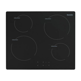
Page 11: Control Panel Layout
Control panel layout 1) ON/OFF button 2) Safety lock b utton 3) LED display 4) Plus button 5) Minus button ) Cooking zone selection buttons (x 4) sing the ceramic hob Before first use IMPORTANT: You should clean the ceramic hob surface see “Cleaning and maintenance”... -
Page 12: Touch Controls
ouch controls o All operations are performed by me ans of the touch controls that can be found on the control panel. o Each touch control has a visual display that corresponds to it. alibration of touch controls o When the hob is powered on for the first time (or after a power cut), it generates a reset in the u ser interface and the control panel will need to be re-calibrated. -
Page 13: Switching The Hob On
Switching the hob on o When the hob is c onnected to a power supply, an audible signal will sound. o The hob will enter entered stand-by mod e after 10 seconds of inactivity and the display will turn off. Press the ON/OFF button (1) to turn the appliance on/off. -
Page 14: Hob Zone Booster
o Each cooking zone has a power range of 1 – 9. At power level “0” the cooking zone will be turned off. o When the cooking zone indicator shows the power level that you require, release th e plus and minus buttons and the cooking zone will start to heat. -
Page 15: Switching Off A Zone Gradually
witching off a zo ne gradually o Press the cooking zone selec tion button (6) of the cooking zone that you want to switch off. o Repeatedly press or press and hold down the minus button until the number in the cooking zone indicator reaches “0”. After a few seconds, the cooking zone will switch off. -
Page 16: Switching The Hob Off
witching the hob off Once you hav e switched off all of the cooking zones, you should switch e hob off. o Press the ON/OFF button (1). o It is possible to turn the hob o ff at any time by pressing the ON/OFF button. -
Page 17: Cookware That Is Suitable For An Induction Hob
Cookware that is suitable for an induction hob The table below shows c ookware that is normally suitable for use on n induction zone hob:- Cookware Suit able Steel, enamelled steel Cast iron Stainless steel state ufacturer) Aluminium, copper, brass Glass, ceramic, porcelain o The bottom of the pans should be as flat and thick as possible. - Page 18 o Press the cooking zone selection button again and the LED display will show “t” where the power level used to be. o The time will be displayed either above or below the selected cooking zone. o Use the plus (4) and minus (5) buttons to set a countdown time of between 1 and 99 minutes.
-
Page 19: Checking The Countdown Time
Checking the countdown time o To check the remaining timer duration, press the relevant cooking zone selection button (6). o After a few seconds the display will revert back to showing the power level. Changing the countdown time o Whilst a countdown is in progress, press the relevant zone selection button as outlined above. -
Page 20: Locking The Hob Top
Locking the hob top o The whole hob top can be locked by pressing the safety lock button (2). You can lock the hob whilst the appliance is switched on, or when it is off. o An LED light will illuminate above the lock symbol when it is activated. -
Page 21: Hob Guidelines
IMPORTANT: The ceramic hob surface is tough; however it is not unbreakable and can be damaged. Especially if pointed or hard objects are allowed to fall on it with some force. o DO NOT USE THE HOB IF THE SURFACE BECOMES BROKEN CRACKED. SHOULD CONTACT BAUMATIC CUSTOMER CARE DEPARTMENT IMMEDIATELY. -
Page 22: Cleaning And Maintenance
Cleaning and maintenance Cleaning operations must only be carried out when the hob is cool. The appliance should be disconnected from your mains supply before commencing any cleaning process. Cleaning the ceramic hob top Any residues that are left on the hob top surface from cleaning agents will damage it. -
Page 23: Using A Ceramic Hob Scraper
Using a ceramic hob scraper The following guidelines should be followed when using the ceramic hob scraper (not supplied):- o The scraper should be placed on the ceramic surface at an angle. o Residues should be removed by sliding the blade carefully over the ceramic surface. -
Page 24: Installation
Installation The installation must be carried out by a suitably qualified person, in accordance with the current version of the following. o UK Regulations and Safety Standards or their European Norm Replacements. o Building Regulations (issued Department Environment). o Building Standards (issued Scottish... -
Page 25: Installing Above A Built Under Oven
o IMPORTANT: Underneath the appliance there must be a partition made of insulating material (e.g. wood). There must be a gap of at least 20 mm between the underneath of the appliance and this partition. o You must make sure that there is a 5mm gap below the underneath of the worktop at the front edge of the hob. -
Page 26: Unpacking The Appliance
When unpacking the appliance pleas e check that the following items re contained within the packaging:- 1 Baumatic hob 1 Installation and instruction manual 1 Baumatic guaran tee card 4 Fixing brackets Fixing screws nstalling the appliance o Cut a hole in the worktop that corresponds with the drawing shown above. - Page 27 o Carefully turn the hob back over and then gently lower it into the aperture hole that you have cut out. o There are holes on the base of the hob that you can fix the two brackets to. o You should place the bracket on the...
-
Page 28: Electrical Connection
Electrical connection This appliance must be installed by a qualified person in accordance with the latest edition of the I.E.E. Regulations and in compliance with Baumatic’s instructions. Before connecting the appliance, make sure that the supply voltage marked on the rating plate corresponds with your mains supply voltage. -
Page 29: Replacing The Mains Supply Cable
o The brass links must be positioned as shown in the photograph on the previous page and once established ALL terminal screws must be tightened down firmly. o You should use a good quality screwdriver to carefully, fully tighten ALL of the terminal screws. o If when the hob is first switched on, only two of the zones work, you should recheck that the terminal screws are all fully tightened. -
Page 30: My Appliance Isn't Working Correctly
* IMPORTANT: If the cooking zone does appear to be hotter than 55°C and the residual heat indicator has not come on, you should call the Baumatic Customer Care Department. o A humming sound is heard when a cooking zone is selected. -
Page 31: Error Codes
Error codes The following error codes may appear in the timer display if there is a problem with the operation of the hob. Fault Possible cause Solutions F0, FA, FC, FU, Electronic fault. Contact the Customer Care Micro-emitter or Department micro-receiver fault. - Page 32 Or any installation other than the one specified by Baumatic Ltd. has been completed. Please refer to the conditions of guarantee that appear on the...
-
Page 33: Contact Details
Czech Republic United Kingdom Baumatic CR s.r.o. Baumatic Ltd., Lípovà 665 Baumatic Buildings, 460 01 Liberec 4 6 Bennet Road, Czech Republic Reading, Berkshire RG2 0QX +420 483 577 200 United Kingdom www.baumatic.cz Sales Telephone Slovakia (0118) 933 6900 Baumatic Slovakia, s.r.o.
Need help?
Do you have a question about the BHI600 and is the answer not in the manual?
Questions and answers