Table of Contents
Advertisement
Quick Links
Advertisement
Table of Contents

Related Manuals for Robe Stage Banner 10 AT Series


Summary of Contents for Robe Stage Banner 10 AT Series
- Page 1 Version 1.1...
-
Page 2: Table Of Contents
StageBanner 10 AT Table of contents 1. Safety instructions ......................3 2.Operating determinations....................4 3. Description of the device....................5 4. Installation........................6 4.1 Connection to the mains .................... 6 4.2 Changing the power supply settings ................6 4.3 Rigging the fixture ...................... 7 4.4 DMX-512 connection/connection between fixtures ............ -
Page 3: Safety Instructions
CAUTION! Keep this device away from rain and moisture! Unplug mains lead before opening the housing! FOR YOUR OWN SAFETY, PLEASE READ THIS USER MANUAL CAREFULLY BEFORE YOU INITIAL START - UP! 1. Safety instructions Every person involved with installation and maintenance of this device have to: - be qualilfied - follow the instructions of this manual CAUTION! -
Page 4: Operating Determinations
2.Operating determinations This device was designed for indoor use only. If the device has been exposed to drastic temperature fluctuation (e.g. after transportation), do not switch it on immediately. The arising condensation water might damage your device. Leave the device switched off until it has reached room temperature. -
Page 5: Description Of The Device
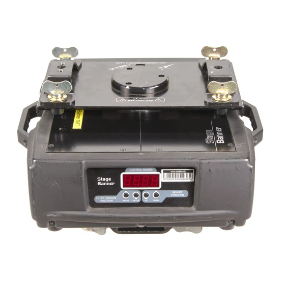
3. Description of the device 1- Quick-lock fastener 2 - Omega holder 3 - Rotating plate 4 - Top covers Rear panel of the fixture 5- Power switch 6 - Power cord 7 - Fuse holder 8 - 3-pin DMX output 9 - 3-pin DMX input 10 - 5-pin DMX output 11 - 5-pin DMX input... -
Page 6: Installation
4. Installation 4.1 Connection to the mains Verify the power supply settings before applying power! If you wish to change the power supply settings,see the chapter below. Connect the fixture to the mains with the power cord. If the plug on the flexible cord is not the right type for your socket outlets,do not use an adaptor,but remove the plug from the cord and discard.Carefully prepare the end of the the supply cord and fit a suitable plug. -
Page 7: Rigging The Fixture
4.3 Rigging the fixture DANGER TO LIFE! Please consider the respective national norms during the installation! The installation must only be carried out by an authorized distributor! The installation must always be secured with a secondary safety attachment, e.g. an appropriate catch net. This secondary safety attachment must be constructed in a way that no part of the installation can fall down if the main attachment fails. - Page 8 Possible Installation: advertising plate clamp fixing clamp safety cable Omega holder rotating plate Overhead installation: 1.Bolt each clamp (1) (not included) to the omega holder (4) with M12 bolt and lock nut through the hole in the holder. 2.Fasten the omega holders on the bottom of the base by inserting both quick-lock fasteners (3) into the holes of the base and tighten fully clockwise.
-
Page 9: Dmx-512 Connection/Connection Between Fixtures
4.4 DMX-512 connection/connection between fixtures The fixture is equipped with both 3-pin and 5-pin XLR sockets for DMX input and output.The sockets are wired in parallel. Only use a shielded twisted-pair cable designed for RS-485 and 3-pin or 5-pin XLR-plugs and connectors in order to connect the controller with the fixture or one fixture with another. -
Page 10: Stagebanner 10 At-Dmx Protocol-Version 1.0
5. StageBanner 10 AT - DMX Protocol-version 1.0 Channel Value Function Type of control Pan coarse 0 - 255 proportional Coarse control of pan movement by 360° Pan Fine 0 - 255 proportional Fine control of pan movement Pan speed step Max. -
Page 11: Operating Modes
6. Operating modes 6.1 Controller mode The fixtures are individually addressed on a data link and connected to the controller.The fixtures respond to the DMX signal from the controller. The control panel on the front panel of the fixture allows you to assign the DMX fixture address, which is defined as the first channel from which the StageBanner 10 AT will respond to the controller. -
Page 12: Control Menu Map
7.Control menu map Default settings=Bold print A001 dM.Ad. MA.SL. d.AbL MASt. SLA.1 SLA.9 SL.Ct. InFo Po.ti. totl rSEt tEMP. Cur.t. Hi.tE. rSEt DM.In. PAn (0-255) F.PAn (0-255) SPEd (0-255) Func. (0-255) VErS. IC1.b. IC2.b. IC3.b.. PErS. r.PAn (On,Off) dISP. turn (On,Off) d.On (On,Off) d.Int.(20...100) FEEd. - Page 13 tESt St.AL. Audi.(On,Off) Auto tESt PrG.1 PrG.2 PrG.3 PLAY tESt PrG.1 PrG.2 PrG.3 Edit PrG.1 PrG.2 PrG.3 St.01 St.99 Pan (0-255) S.tim.(0.1-25.5) (s) COPY rESE. SPEC. CodE uPd.M.(No,Yes)
-
Page 14: Control Menu
8. Control menu The control panel situated on the front panel of the base offers several features. You can simply set the DMX address,read the number of unit hours, run test, make a reset and also use many functions for setting fixture behaviour. -
Page 15: Personality
Current temperature on the main board in the base of the fixture.If temperature exceeds 87°C,the fixture will go to the "Power down" mode. Hi.tE. --- Maximum fixture temperature. The function shows the max.temperature on the main board since the StageBanner 10 AT has been fabricated. HEAd - The function shows the max.temperature of the head inside since the StageBanner 10 AT has been fabricated. -
Page 16: Manual Mode
erating modes. Auto --- The fan automatically raises its speed in order to control inside temperature of the fixture, if the temperature inside increases about certain level.This cycle can repeat several times until the temperature inside is on a suitable level. HIGH --- The cooling fan works on max. -
Page 17: Reset Function
Note:If the fixture operates in the controller mode ( DMX controller is connected) and any program from this menu is selected ,in this case the fixture will not respond to the DMX controller after switching on and will play selected program. PLAY --- Playing program.Select this menu to run a bilt-in program or the 3 freely-programmable programs in a loop. -
Page 18: Low Power Mode
2.Make a new directory ( e.g. Robe_Uploader) on your hard disk and download the software to it. 3.Unpack the program from the archive. If the Robe fixture is produced in magnetic and electronic ballast version, name of DMX Software Uploader is the same for both versions. -
Page 19: Error And Information Messages
10. Error and information messages Mb.Er. This messsage informs you that the main PCB does not communicate correctly with the Control Board. Fr.Er. This message will appear if the frequency of the main is not standard 50 or 60 Hz.This message can appear as a result of the interference during the lamp starting (if the lamp or igniter is old) or as a result of the interference by neighbouring devices. -
Page 20: Maintenance And Cleaning
Dimensions(mm) Weight (net): 12 kg Accessories Omega holder (4 pieces)........No.99010420 12. Maintenance and cleaning It is absolutely essential that the fixture is kept clean.Dust must be cleaned from the fan and air vents periodically.The interior of the fixture should be cleaned at least annually using a vacuum-cleaner or an air- jet.
Need help?
Do you have a question about the Stage Banner 10 AT Series and is the answer not in the manual?
Questions and answers