Table of Contents
Advertisement
Quick Links
Advertisement
Table of Contents

Related Manuals for Robe Led Blinder 196 LT


Summary of Contents for Robe Led Blinder 196 LT
- Page 1 version 1.3...
-
Page 3: Table Of Contents
4.3 Rigging the fixture ...................... 6 4.4 Fitting the frost filter....................7 5.Led Blinder 196 LT-DMX protocol ,version 1.1 ............. 8 6.Led Blinder 196 LT - Control menu map ..............10 7.Control board......................... 11 7.1 Addressing the LedBlinder 196 LT ................11 7.2 Program running ...................... -
Page 4: Safety Instructions
CAUTION! Unplug mains lead before opening the housing! FOR YOUR OWN SAFETY, PLEASE READ THIS USER MANUAL CAREFULLY BEFORE YOU INITIAL START - UP! 1. Safety instructions Every person involved with installation and maintenance of this product has to: - be qualilfied - follow the instructions of this manual CAUTION! Be careful with your operations. -
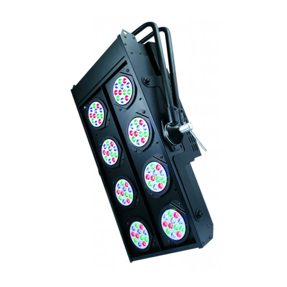
Page 5: Description Of The Ledblinder 196 Lt
3.Description of the LedBlinder 196 LT 1 - Mounting yoke 2 - "T" bar 3 - LED modules Control board 1 - 5-pin DMX output 2 - 3-pin DMX output 3 - 5-pin DMX input 4 - 3-pin DMX input 5 - LED display 6 - Mode-button 7 - Enter-button... -
Page 6: Dmx-512 Connection/Connection Between Fixtures
4.2 DMX-512 connection/connection between fixtures The fixture is equipped with both 3-pin and 5-pin XLR sockets for DMX input and output.The sockets are wired in parallel. Only use a shielded twisted-pair cable designed for RS-485 and 3-pin or 5-pin XLR-plugs and connectors in order to connect the controller with the fixture or one fixture with another. -
Page 7: Fitting The Frost Filtr
The fixture should be hung on a truss structure using a mounting clamp (not included).Mounting yoke has a 13 mm diamer hole for fixing the mounting clamp.The fixture can be tilted + - 180°.The required tilt angle of the fixture can be adjusted by means of the "T" bar on the side of the fixture. The installation must always be secured with a secondary safety attachment, e.g. -
Page 8: Led Blinder 196 Lt-Dmx Protocol ,Version 1.1
5.Led Blinder 196 LT-DMX protocol ,version 1.1 Mode/Channel Value Function Type of control Zone 1 Red LEDs 1 0-255 Red LEDs saturation control (0-100%) proportional Green LEDs 1 0-255 Green LEDs saturation control (0-100%) proportional Blue LEDs 1 0-255 Blue LEDs saturation control (0-100%) - Page 9 128-135 Macro 16 step 136-143 Macro 17 step 144-151 Macro 18 step 152-159 Macro 19 step 160-167 Macro 20 step 168-175 Macro 21 step 176-183 Macro 22 step 184-191 Macro 23 step 192-199 Macro 24 step 200-207 Macro 25 step 208-215 Macro 26 step...
-
Page 10: Led Blinder 196 Lt- Control Menu Map
6.Led Blinder 196 LT- Control menu map Default settings=Bold print A001 (001-498) ProG EPG.1 EPG.2 EPG.3 PrG.1 PrG.6 Auto (OFF,On) Edit. EPG.1 EPG.2 EPG.3 St.01 St.30 P.End rEd 1 (0-255) dimr. (0-255) F.tim.(0-255) S.tim. (0-255) COPY. MAn.C. rEd (0-255) GrEE. (0-255) -
Page 11: Control Board
7.Control board The control panel situated on the top cover of the LedBlinder 196 allows DMX addressing,calling build-in pro- grams and setting the fixture behaviour. Control elements on the control board: [MODE] button-leaves menu without saving changes. [ENTER] button- enters menu,confirms adjusted values and leaves menu. [UP] button and[DOWN] button- moves between menu items on the the same level, sets values. -
Page 12: Manual Mode
rEd.3 - a red LEDs 3 saturation,value 0-255 rEd.4 - a red LEDs 4 saturation,value 0-255 GrE.3 - a green LEDs 3 saturation,value 0-255 GrE.4 - a green LEDs 4 saturation,value 0-255 bLu.3 - a blue LEDs 3 saturation,value 0-255 bLu.4 - a blue LEDs 4 saturation,value 0-255 Following item are common for all zones: MACr. -
Page 13: Test Sequences
7.4 Test sequences Use the item to run a special demo-test sequences without an external controller,which will show you some possibilities of using the fixture. 7.5 Stand-alone mode Synchronous operation of multiple fixtures requires that they must be connected on a data link and one of them is set as a master ("MASt.") and the rest as the slaves ("SLA.").Only one fixture can be set as the master.The slaves mimic the behavior of the master.Effect actions are triggered by an internal timer of the master fixture. - Page 14 To update software in the fixture: 1.Installation of DMX Software Uploader: 1.DMX Software Uploader program is available from the ROBE web site at WWW.robe.cz. 2.Make a new directory ( e.g. Robe_Uploader) on your hard disk and download the software to it.
-
Page 15: Technical Specifications
Led Blinder 196 - Technical Specifications Power supply: Input Voltage:100-240V AC, 50/60 Hz Fuse:T 3.15A Max.Pover Consumption:140VA Input: Control:DMX 512 DMX connection: 3-pin or 5-pin XLR-sockets DMX channels: Mode 1: 15 channels Mode 2: 12 channels Mode 3: 6 channels Mode 4: 3 channels LED beam angle: Each LED has 25°... -
Page 16: Maintenance
Optional Accessories Set glass frost (No.99011539) Set film frost (No.99011540) Cover for LED Blinder 196 (No.10980037) 9.Maintenance Keep the Led Blinder 196 dry. Operate only in places where the sufficient airflow to cool the fixture is present Periodically clean the front transparent cover of LED modules Use a moist, lint-free cloth.
Need help?
Do you have a question about the Led Blinder 196 LT and is the answer not in the manual?
Questions and answers